David H. Bronke
-
Quick and dirty soldering iron stand
09/28/2019 at 06:18 • 0 commentsMade a quick stand for me iron tonight, out of part of an old microwave's case. It's ugly and pretty terrible, but it gets the job done. Pretty much just cut a strip out of the sheet metal and drilled a 5/16" hole.
-
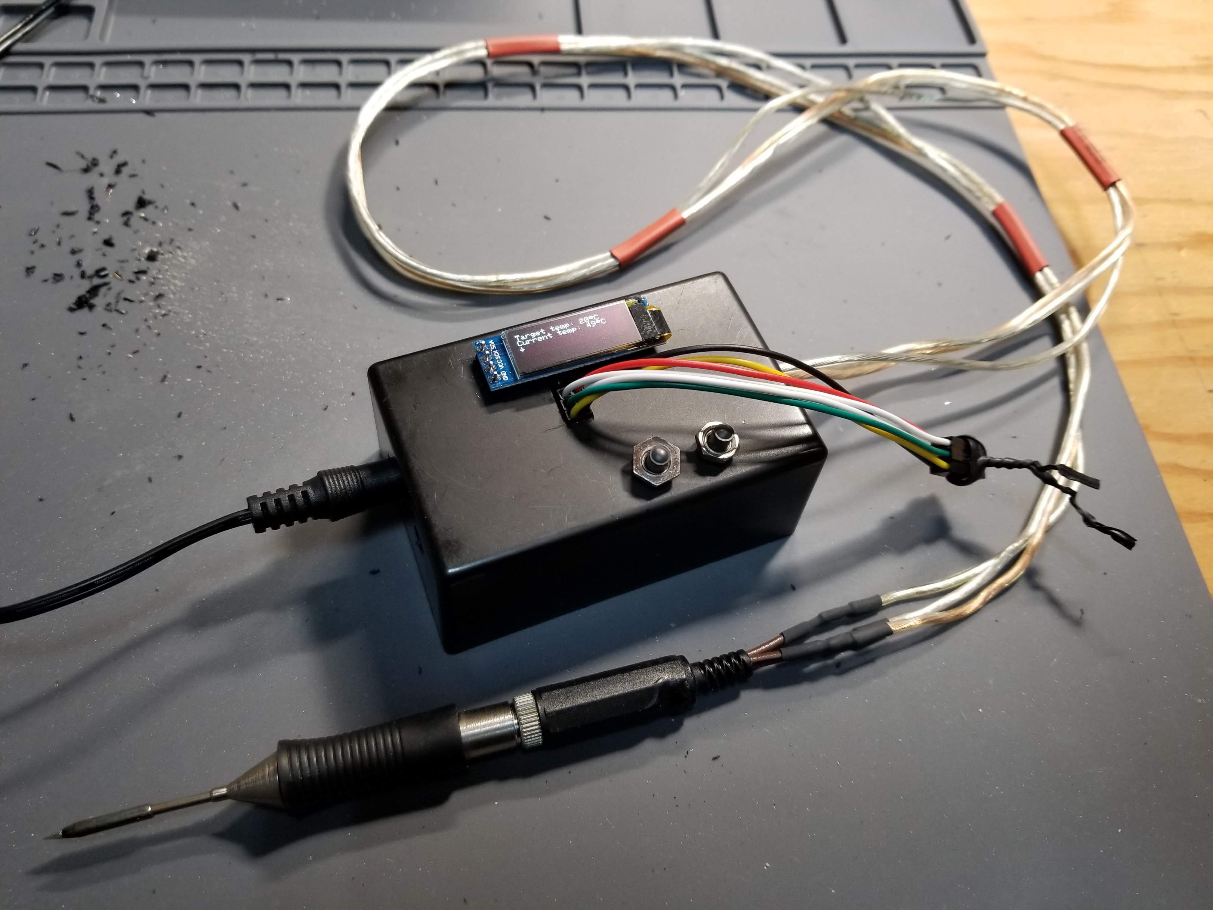
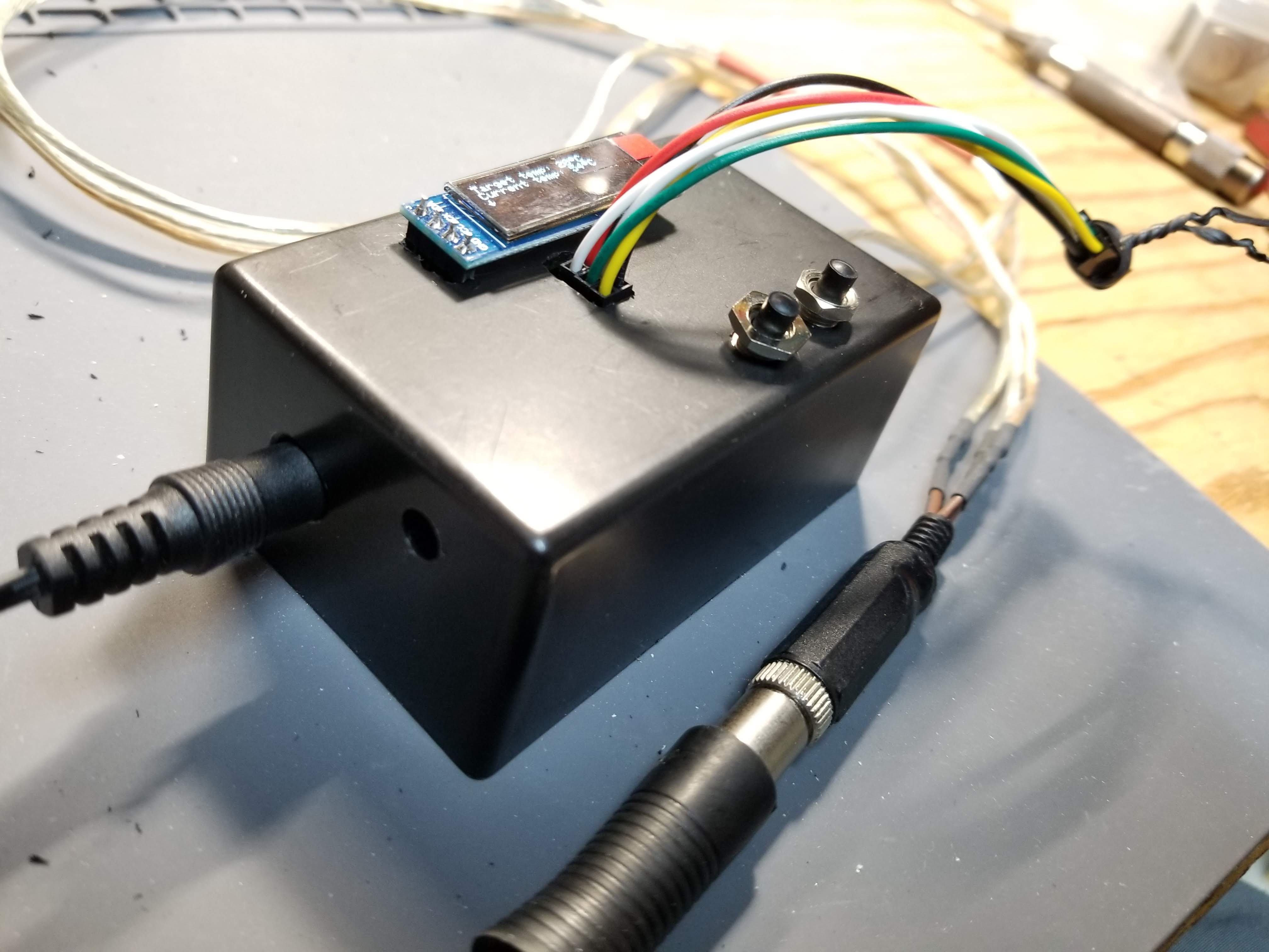
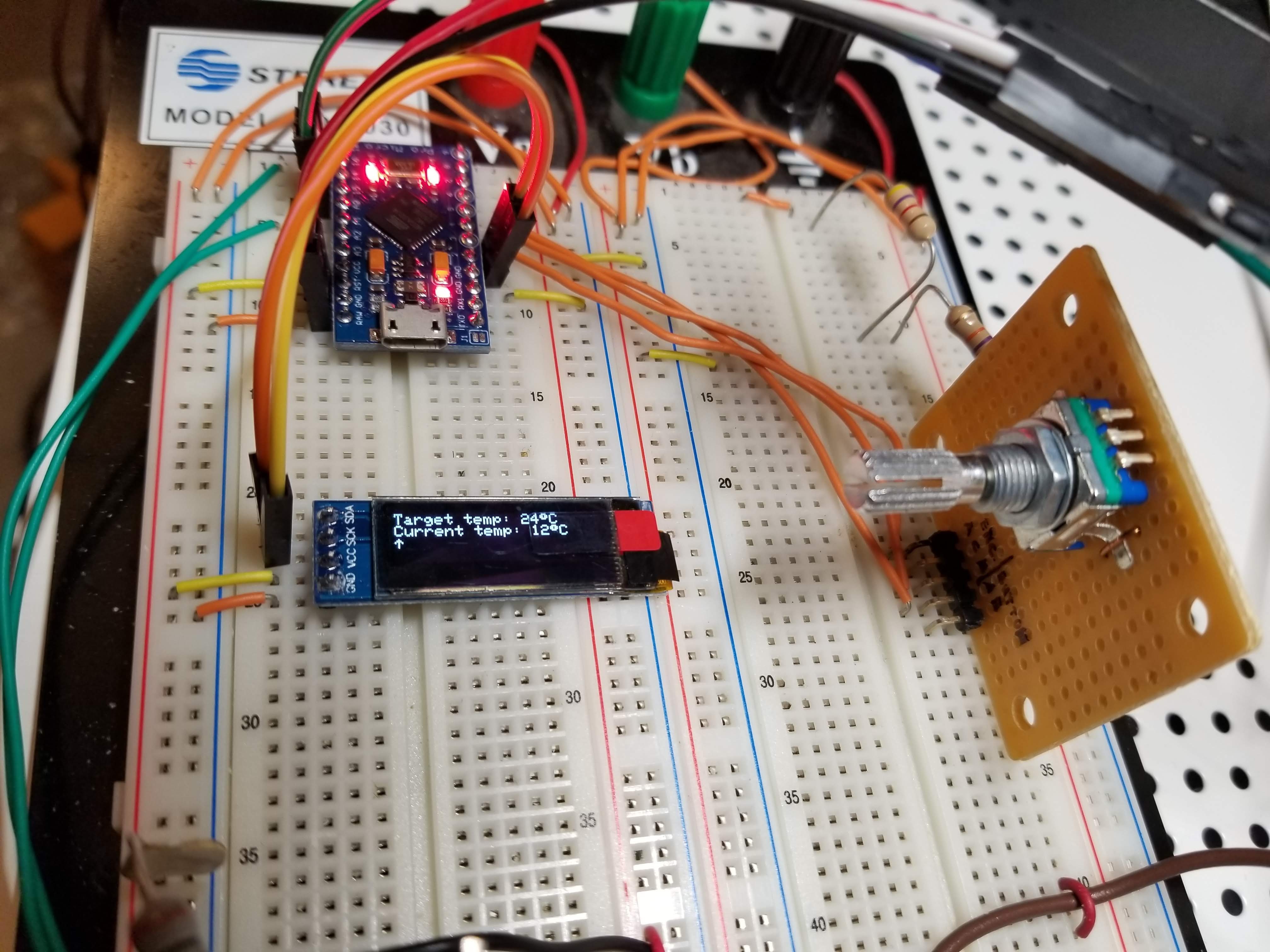
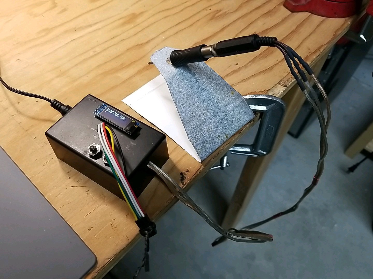
In a box!
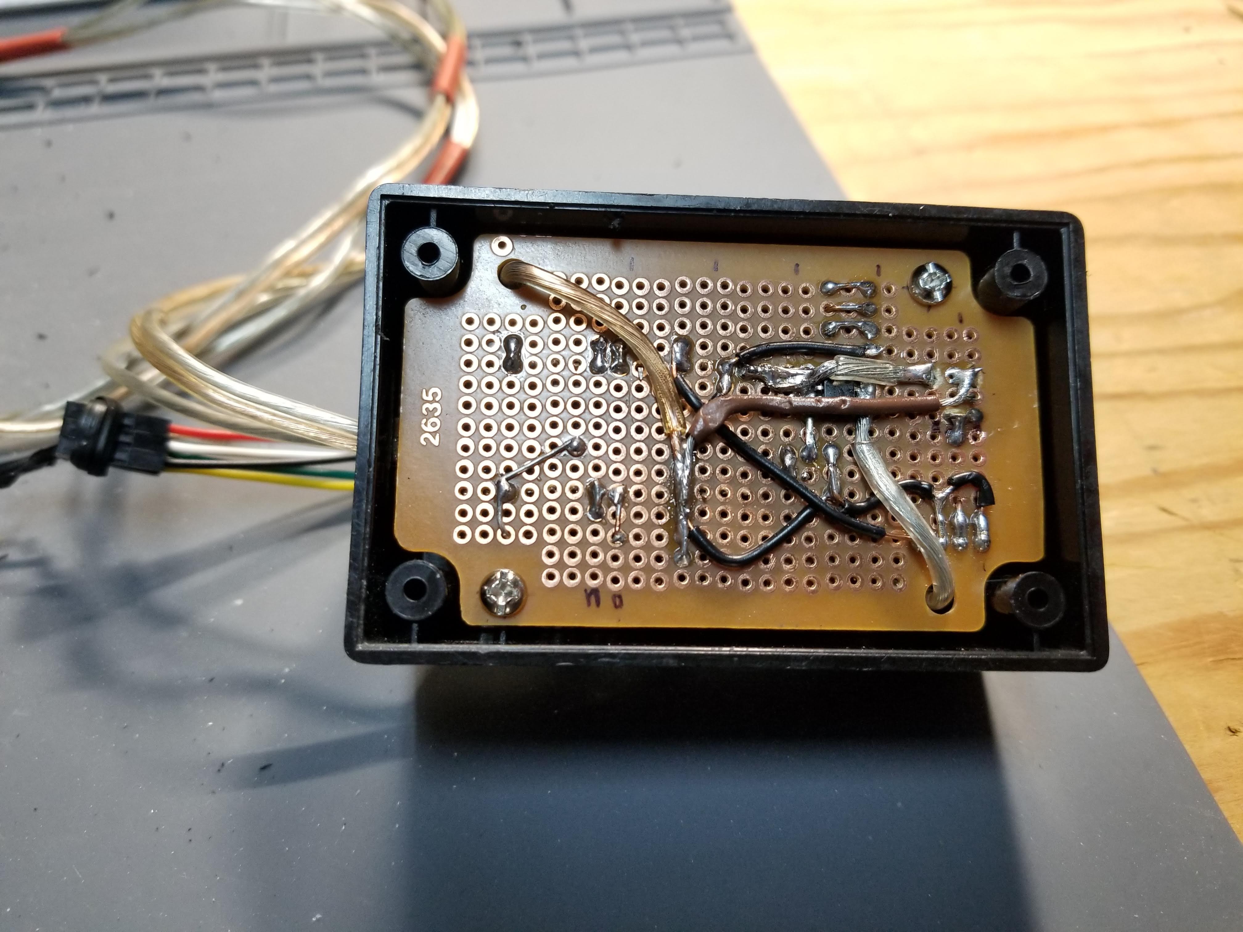
09/25/2019 at 07:31 • 0 commentsSo, I finally go around to transferring this from the breadboard to a protoboard with its own enclosure. Looks kinda hacky, but it works great!
![]() ---------- more ----------
---------- more ----------More glamour shots:
![]()
My wonderful solder job. Sadly, I had already crammed the whole thing into the box before I thought to take any photos. Also, I seem to have lost the cover for the project box, so it's currently open on the bottom.
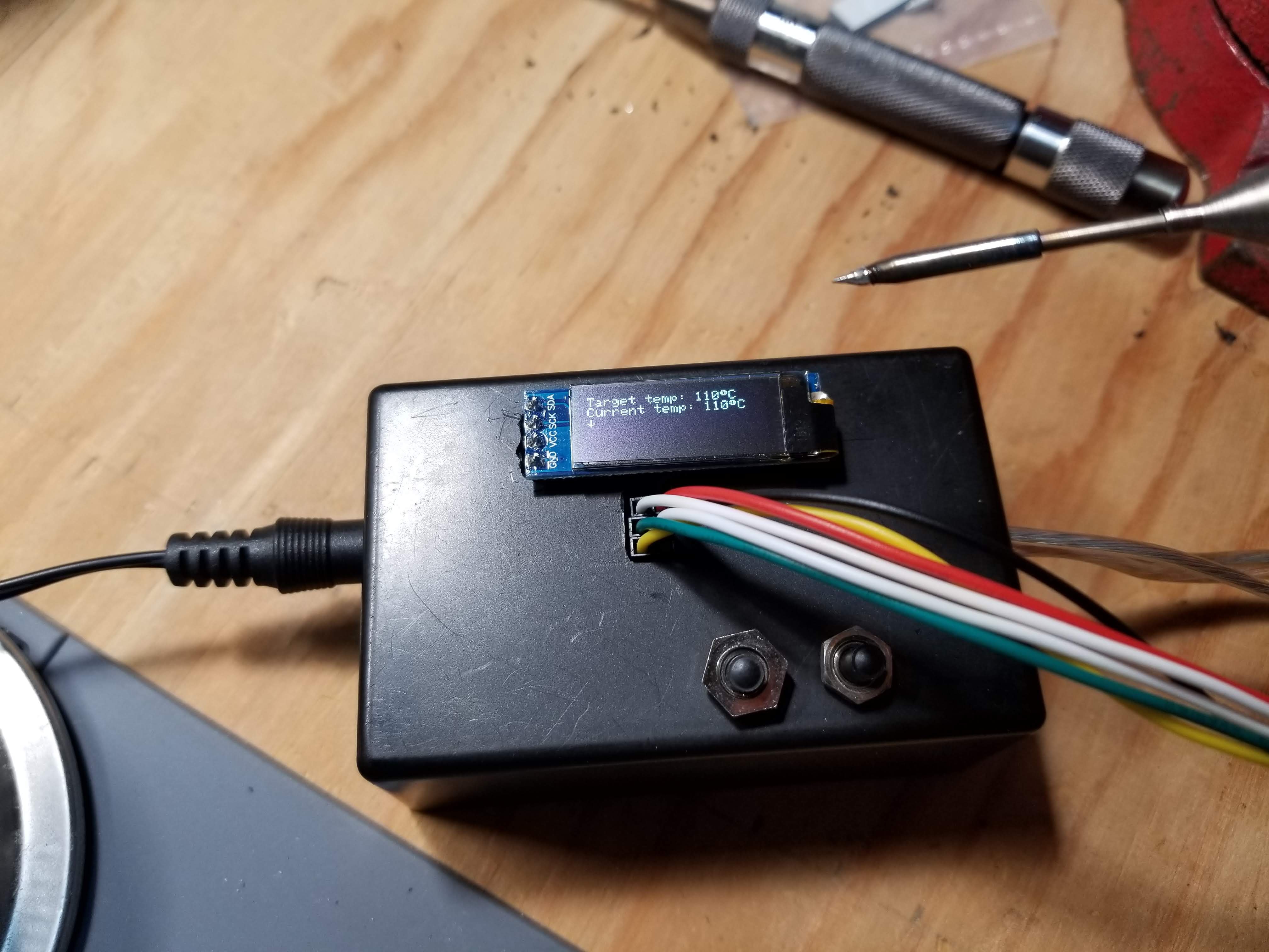
![]()
Somehow, this thing actually worked the first time I plugged it in. I'm still shocked.
![]()
The temperature control is still about as accurate as it's ever been. (read: not very, but at least it's consistent)
![]()
This would be a great marketing shot, if it weren't for my terrible case job.
- Those nuts are the wrong thread, so they're just cross-threaded on enough to stop the buttons from falling back into the box.
- The extra hole on the side was my first attempt at routing the ICSP header out of the box, but the connectors were too tall, so... now it just sort of hangs right out the front plate. Yes, that's a twist tie.
- The OLED of course had to be external to make things line up conveniently given the parts I had on hand. (I used an old wire-wrap IC socket plugged into a regular socket on the perfboard, and then plugged the OLED into the wire-wrap socket through a hole in the case)
- The old, melted stereo jack is back, because I accidentally melted my second nice red one too much while trying to solder it. This one at least works, and the tip doesn't just fall out of it.
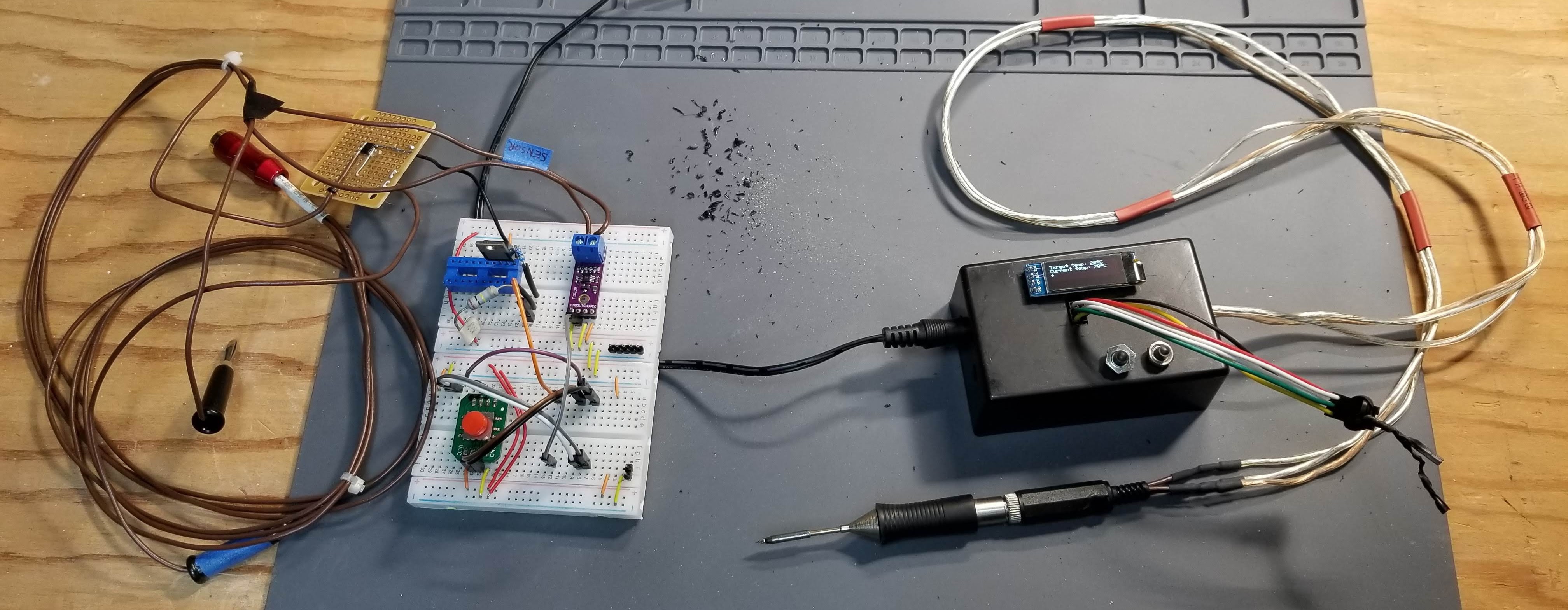
![]()
The old and new side-by-side. Here you can see that I've pulled some parts from the old one: the OLED and the Arduino Nano now live in the new box, and the rest of these parts will probably be pulled off the breadboard soon.
All in all, I'd say this project has been a success! I may pursue getting some actual boards printed professionally and maybe 3D-printing a custom enclosure, but for now I'm pretty happy that I managed to build my own soldering iron controller that works so much better than any of the other irons I own.
One more thing I'll probably change soon, though: I want to get some terminal blocks so the cord is completely removable without unsoldering or cutting wires. That way I can swap it out for a better cord once I find some 3-conductor stranded shielded cable and get a new stereo jack. Oh, and a power switch might be nice. Maybe I'll make use of that extra hole in the side?
-
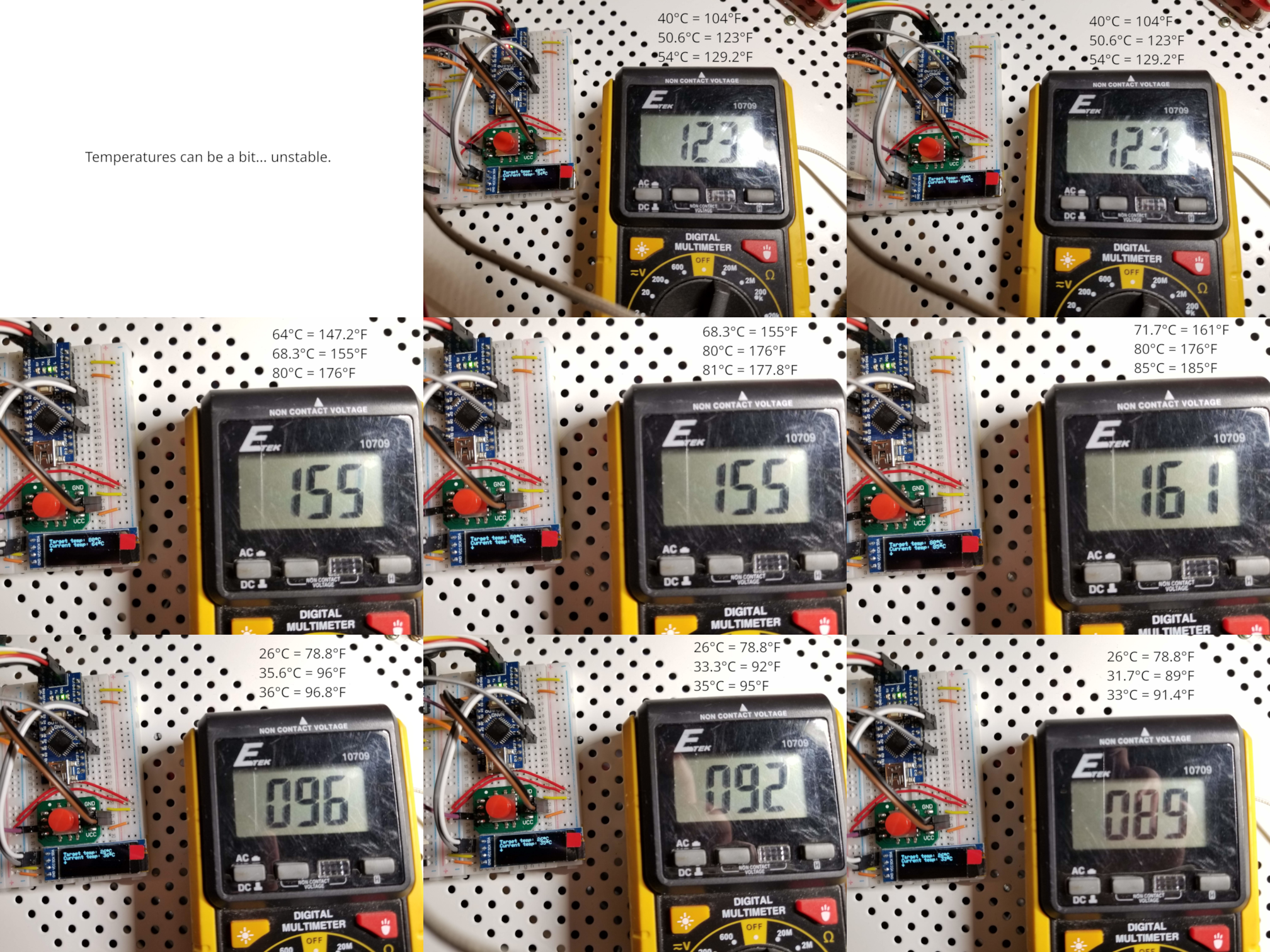
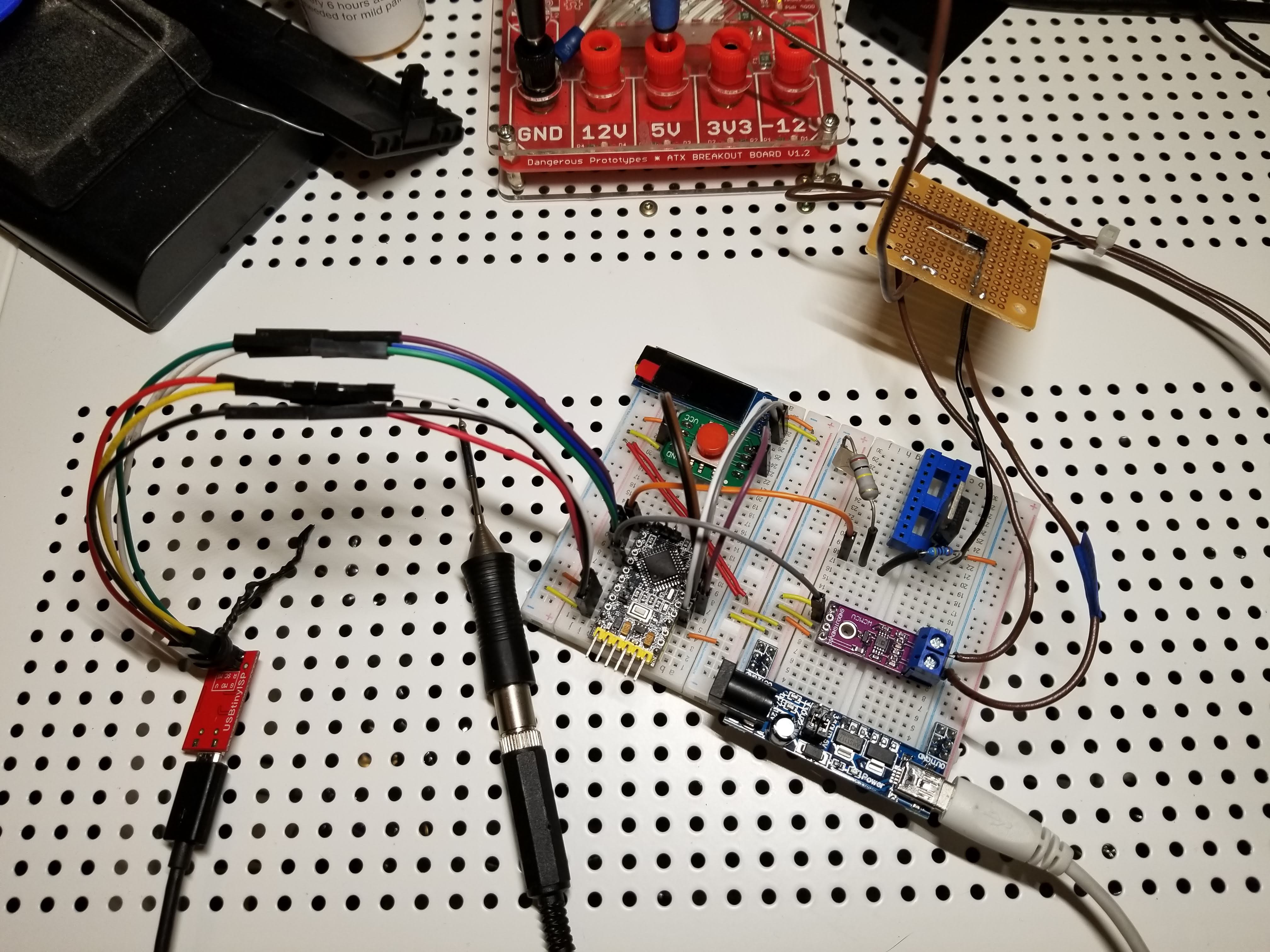
Temperature testing
08/19/2019 at 00:29 • 0 commentsSo, I managed to get everything working well, and even managed to tin the tip! However, the thermocouple in my RT-1 seems to be rather inaccurate. (also, the readings vary quite a bit... not sure what to do about that yet)
![]()
---------- more ----------
I realized that low power scenarios can affect the temperature reading quite a bit (e.g., when powering it from my USBtinyISP, the temperature reading is about 20 degrees higher than when powering the board on its own), and the original headphone jack no longer makes good contact with the tip. (it melted at the same time as I overheated the tip) So, I'm finally getting around to putting on a new jack! This one has a nice solid metal case, and seems much more robust than the one I had on there.
Also, I adjusted the code to do temperature readings in bursts - 5 times in a row with only 5ms delay between them - and average the readings. This made the readings much more stable, though there still seems to be some adjustment necessary; the thermocouple still shows the actual temperature to be significantly higher than what the tip is reading.
I also noticed some pretty loud noise coming from my power supply while the PWM is running, so I started looking into decoupling capacitors, but none of the combinations of capacitors and inductors I tried had any noticeable effect. I even tried a ZNR. I'll dive into that again later.
Also, I tweaked the firmware so the MODE button causes the PWM on the heater to go up to full, and wired up my ammeter so I could figure out how much current this thing draws. Started it up, held down MODE for a bit... 5A. Wow. Did it again (apparently without waiting long enough for the tip to cool) and the tip actually got red hot, but only drew about 3.5-4A. Luckily this is the same tip I had already overheated a while ago, and this time the stereo jack connection didn't seem to heat up at all! The solder on the tip had definitely oxidized, but that was simple to clean. Seems like the tip is still surviving all my experimentation!
In light of this, I added a MAX_HEATER_PULSE_WIDTH, and set it to 180 to limit current draw to a bit under 2A.
I also tried out my other new tip, which seems to be a bit more accurate on temperature readings... but it's weird; I wasn't able to tin the tip at all. Solder heats up great when it touches, but it won't wet the tip.
Next adventure will probably be adding PID so we get better temperature stability. (though honestly, this is already way better than any other soldering iron I've used)
-
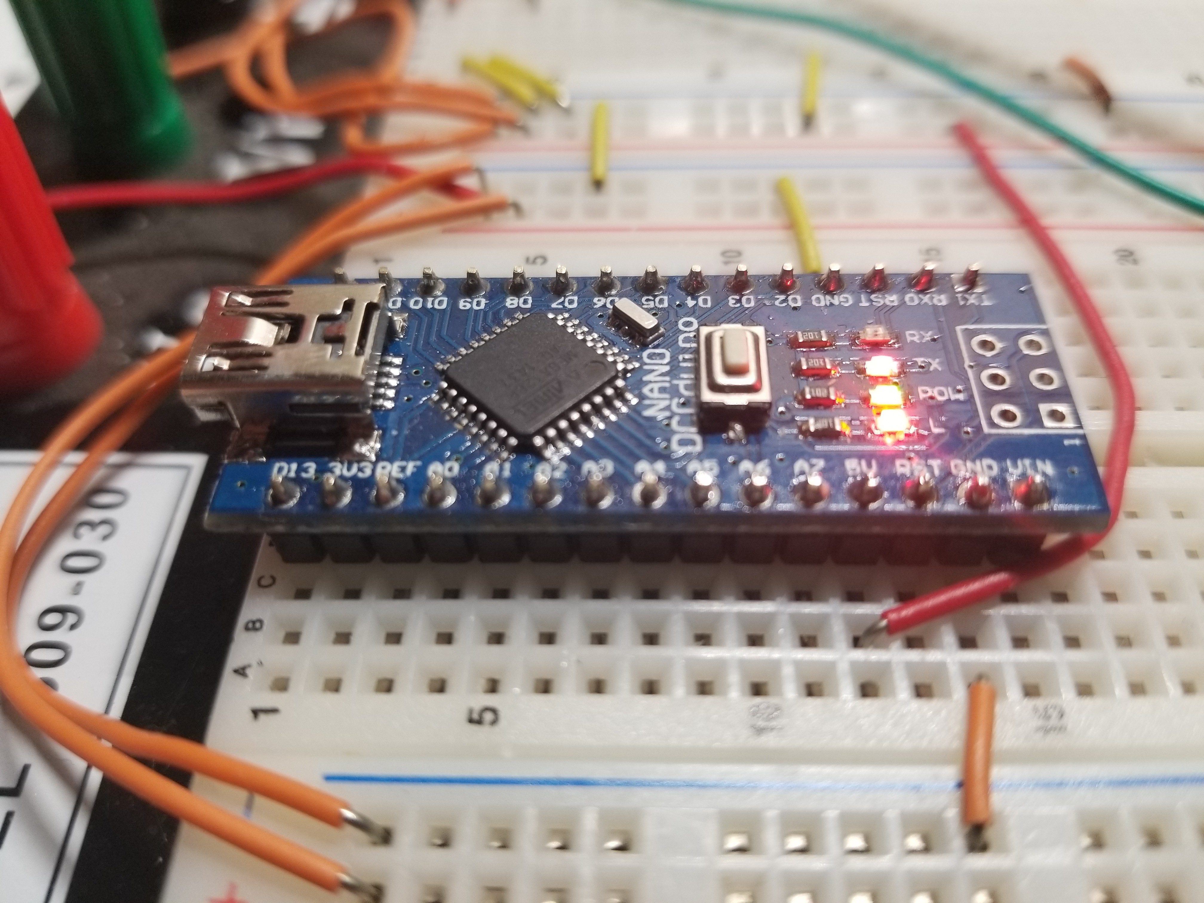
Finally working!
08/17/2019 at 03:45 • 0 commentsTemperature control is working now! Haven't checked with my thermocouple to see if it's accurate, but it gets to the target temperature pretty quickly, and hovers within around ±2°C, even though I haven't implemented PID control or anything yet; right now it's just setting the PWM pulse width to either 254 (for heating) or 8 (for cooling). Once I verify that the detected temperature is decently accurate, I'll raise the maximum temperature and try soldering something!
Also, you may notice that I switched back to the Nano. I still haven't been able to program the WAVGAT Pro Mini boards, so I switched back to one I know will work, and after fixing a couple of bugs in the code, it's doing great! (especially considering I'm still only heating the tip with 5V, not 12V like most of the other designs)
![]()
-
Failure to Program
08/05/2019 at 01:09 • 0 commentsEarlier today, I made what I think are the necessary changes to the code. I should be able to test everything out now, but I have yet to be able to actually program the Pro Mini. I've tried using the USBTinyISP (which worked fine on the Pro Micro) and the FTDI adapter, but avrdude always fails. I've even pulled the Pro Mini out of the circuit entirely in order to program it, and it still won't work. Probably serves me right for buying cheap knock-off parts from AliExpress.
At any rate, my latest code is pushed to the GitLab repo, so feel free to check it out.
Edit: Apparently, the WAVGAT chips don't work correctly with ISP-style programming (SPI interface) but they do work when you program them via serial using the bootloader. On the other hand, the bootloader doesn't seem to allow you to read the flash, so it can't verify whether or not the write succeeded. I'll be testing it out tomorrow to see if the flash actually took.
Edit 2: Nope. Even though avrdude claimed it succeeded in programming the chip, it doesn't seem to actually do anything when put back in the circuit. I asked the seller on AliExpress about it, and after he shared the same instructions with me that were in the item description, he said he'd refund the $2.82 it cost me for 2 of these. That still means I have 2 of these sitting around, apparently unusable.
Edit 3: I've even tried using LGT's LarduinoISP to program it, clamping directly onto the chip's SWC and SWD pins since they're not exposed on the board... and still, no dice. More discussion can be found at https://hackaday.io/page/6452-wavgat-avga328p
-
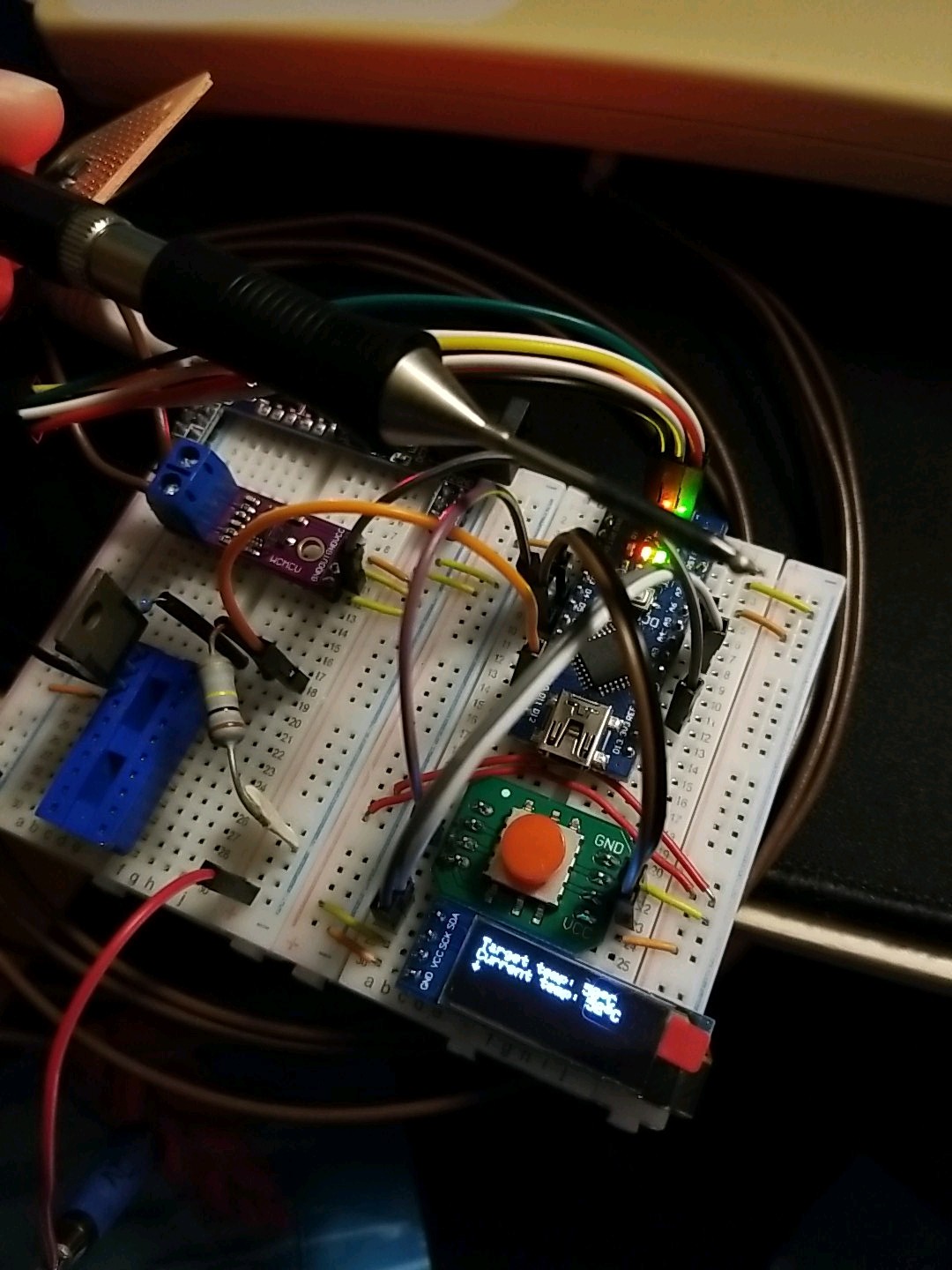
Slow improvements!
08/03/2019 at 17:38 • 0 commentsSince my last project log, I've made a few improvements:
- Swapping out the op-amp circuit for an AD8495-based board
- Swapping out the rotary encoder for a 5-way D-pad
- Switching to the USBtinyISP for programming
- Switching back to another Pro Mini clone, this time with a clone of the ATmega328P instead of the ATmega168
![]() ---------- more ----------
---------- more ----------Thermocouple Reading
Reading the thermocouple via an op-amp was giving me lots of trouble. (see previous project log for more on that) Instead, I opted to switch to a tiny amplifier board based on the AD8495, similar to this one from Adafruit. This should give much more usable results with a much lower amount of effort, though I have yet to update the code so I can test it.
Input!
Reading a rotary encoder on a microcontroller is a pain. It involves getting into decoding Gray code and dealing with interrupts. (otherwise the microcontroller probably won't sense the pin changes quickly enough, leading it to make incorrect assumptions about the direction of rotation, among other things... see previous project log)
Instead of sticking with the rotary encoder, I've decided to switch to this 5-position switch from Parallax that I happened to have lying around. It takes care of the problem without requiring interrupt code, though it's not as convenient a way to control the temperature. Eventually, I'm going to place an order for some of @Saimon's I2CEncoders so I can just pipe them in via I2C instead... but for now, this works.
Code
Sadly, I've been procrastinating on the code side of things. While I have all the hardware wired up, and I've been tweaking the Fritzing sketch to (mostly) match, I have yet to dive back into the code and get it updated for these changes. I'm hoping I'll be able to do that soon, but since we're going to be moving to a new apartment this month, I'm not sure whether that will happen.
One other thing I'd love to do is dive into making some custom components for Fritzing, since the ones I've found don't quite match the components I'm using. On a related note... for components that have a separate breadboard version (with 0.1" pin headers to plug into a breadboard) I'd love the option to be able to actually use that version on the PCB, instead of the stripped-down version. In some cases, the "breadboard" version is all I have.
As usual, all of my current code and Fritzing sketches are on the GitLab project. Please feel free to take a look and/or try them out! -
More reworking, and trouble with thermocouples
03/01/2019 at 05:16 • 0 commentsSo, since the last project log, (actually, since Monday) I've actually switched microcontrollers twice: first, from the Nano to the Pro Mini, and then to the Pro Micro. (the Pro Mini doesn't have enough code space to fit the library for the OLED screen I'm using and still have room for anything else) Oh yeah... I also added an OLED screen!
![]() ---------- more ----------
---------- more ----------I've gotten it up and running, and I'm able to heat the tip up pretty quickly, even at 5V. I also switched from manually-implemented PWM to the built-in PWM in the ATmega32u4, and just turned the PWM frequency way down to not incur too much heat due to switching the MOSFET on and off.
Now, the problem is the thermocouple in the soldering tip. I had started this project out by substituting an OPA4228 in place of the OPA344 used by Hans Peter Haastrup's Soldering Pen project. (which itself was replacing the OPA2336 used by Martin Kumm's SMD Soldering Station) Apparently I didn't set it up correctly, though, since the analog read I'm doing always bounces between 8 and 16, regardless of the actual temperature of the tip. (measured with the thermocouple that came with my multimeter) You'd think I'd be able to get a different reading from a 74°F tip than from a 240°F tip... but then I went back to Martin Kumm's project, and realized that the thermocouple in the tip is rated at about 16 μV/K. So apparently I need much higher gain... which might also mean I'll need a lower noise op-amp.
Update: So, I tried swapping the OPA4228 out for a TL074CN and got excited because it suddenly started reading inputs in the high 800's instead of around 12! But then I realized that apparently this is just a DC offset of some sort; it still doesn't seem to change at all in relation to the temperature of the tip, and messing with the feedback resistors around the op-amp hasn't helped yet. I'm hoping someone else sees what I'm doing wrong, because I'm pretty stumped.
![]()
One more thing I've noticed is that the rotary encoder is... finicky. It seems I'll either have to reimplement the encoder logic using interrupts, or get a different encoder that doesn't have 4 separate transitions per detent.
In the meantime, I've been pushing updates to the GitLab project, including updated Fritzing files. Feel free to check them out and let me know if I messed something up!
-
It lives!
10/01/2018 at 02:26 • 0 commentsSo, I had a realization earlier... the USB interface on the Nano DCCduino is actually on a separate chip. On a hunch, I plugged it into the breadboard to see if it would light up if I powered it externally...
![]()
Well, then. That makes things easier.
So, in light of this... I'll be switching back to using the Nano for this project. (more pins makes a lot of things easier, and I won't need to worry about weird DigiSpark-specific library ports) I just need to solder the ICSP pins on and hook up my BusPirate, and I'll be back in business.
-
Serial output and freezing weirdness
09/16/2018 at 17:28 • 0 commentsNow that I've switched to the Digispark for the brain of this project, I've updated the code to support it (using a preprocessor define so we can switch between that and the Nano) and added in a software-based serial port for communication. (I couldn't get the Digispark's software serial-over-USB to work, and it doesn't have a hardware serial port apparently)
The weirdest thing here is that I got no output on the serial port TX line at all for quite a while... until I unplugged the heat sensor amp circuit from the Digispark. The heater control circuit is apparently fine, but something about the OPA4228PA's output was apparently killing the Digispark - when it was plugged in, I couldn't even get lights to blink!
I'm really kinda stumped on this one... I don't understand why connecting the output of an op-amp to an input pin would cause the whole microcontroller to freeze. I've pushed my latest changes to the GitLab project, if anyone reading this would like to take a look and maybe fill me in on what I'm doing wrong. (the Fritzing file for the Digistump version of the circuit is available here)
-
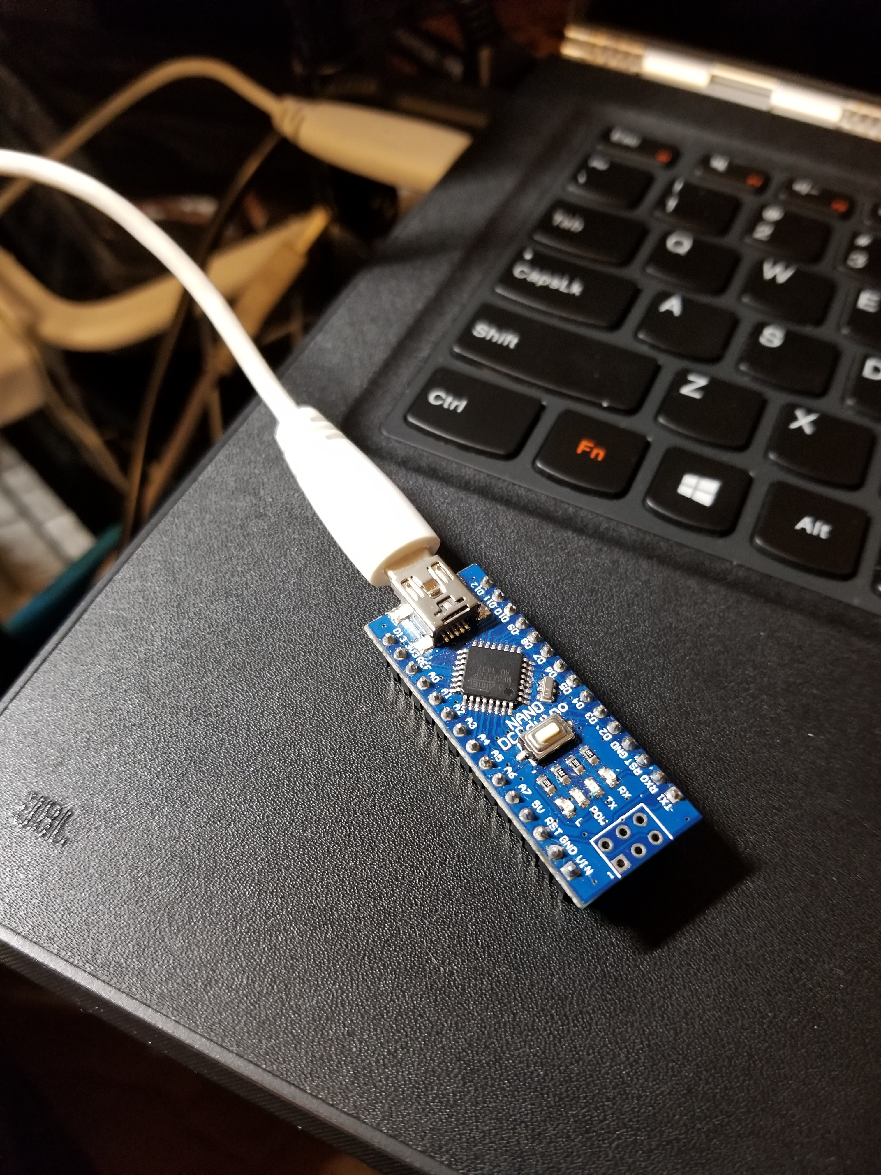
R.I.P., Nano DCCduino
09/15/2018 at 23:52 • 0 commentsSo, after I started troubleshooting why it was behaving as if the Mode button was always pressed, I found out that that actually was the case; the button I was using was broken, and was always a closed circuit. Once I removed it, suddenly the Nano shut off, and since then I haven't been able to get any response out of it; not even the power light comes on, and it doesn't show up in dmesg.
![]()
Rest in peace, Nano. The last couple of days were brief, but enjoyable.
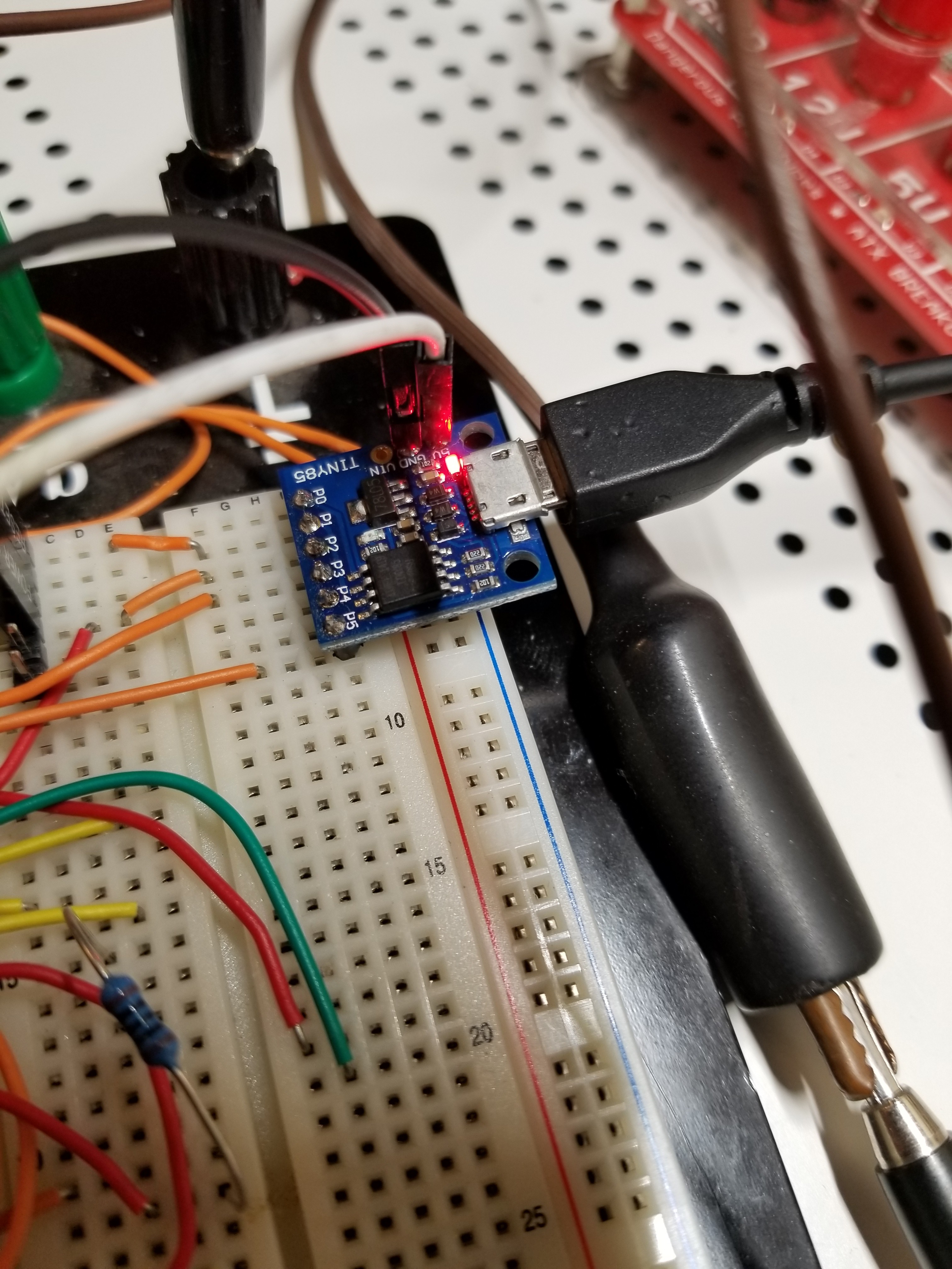
Since the only Nano I have has now passed on, I needed to find something else to drive this whole project. I could have pulled out another of the PICs I have in store, but honestly... they're more of a pain than I want to deal with right now. So instead, I dug up this tiny one:
![]()
It's apparently a Digispark clone, and it was given to me a couple of years ago by the same friend who donated the Nano. (thanks, Rusty! I couldn't have done this project without you :D)
Turns out, if I'm not tied to driving an LED display, I can do everything on 4 I/O pins, and still have a serial connection for doing stuff like display, if I get creative. (maybe I'll make a companion app for my Raspberry Pi Zero or something) Sadly, it can't do the serial monitor over USB like the Arduinos can, but there's other ways to get output.
If all else fails, I have an MSP430 (also given to me by the same friend), and I also still have a new "Pro Mini" Arduino clone coming... which is basically a Nano without USB.