 Gerben
-
1Mark led positions
![]()
(The dog inspected, and approved my work) -
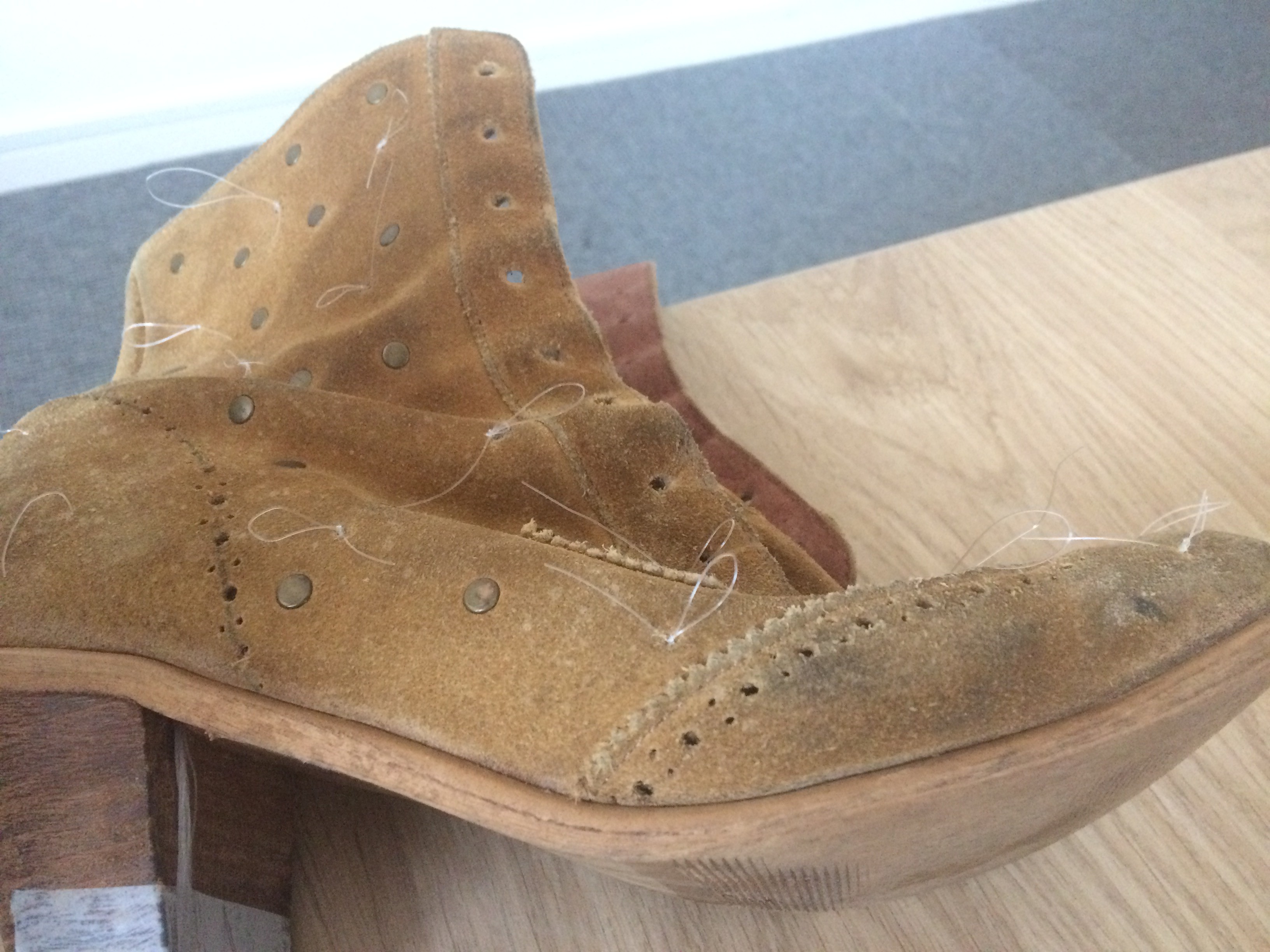
2Pull fishing wire
Since I wanted all the electronics to be attached to the inside of the heel, all the wires for the leds had to get to this spot. So I tried to drill a hole, right in the center of the sole. Not a great idea, as apparently there's a piece of very hard metal embedded in the sole, to prevent flexing. Two drillbits later, I figured this out, and decided to drill more to the side of the sole.
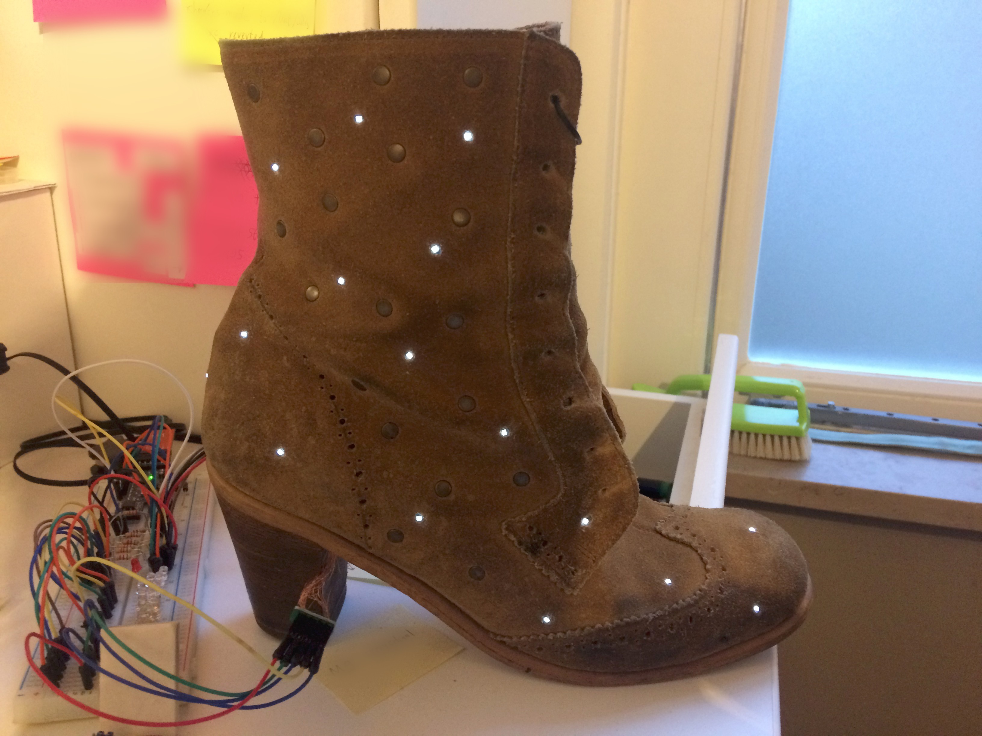
Using a small drill bit in my hand, and made a small hole in the leather where each of the leds were going to be. Using a dremmel, with an engraving bit I removed tiny bit of the thickness of the leather, so each leds would sit slightly below the surface. This will make the leds blend in more, and reduce the risk of getting damaged.
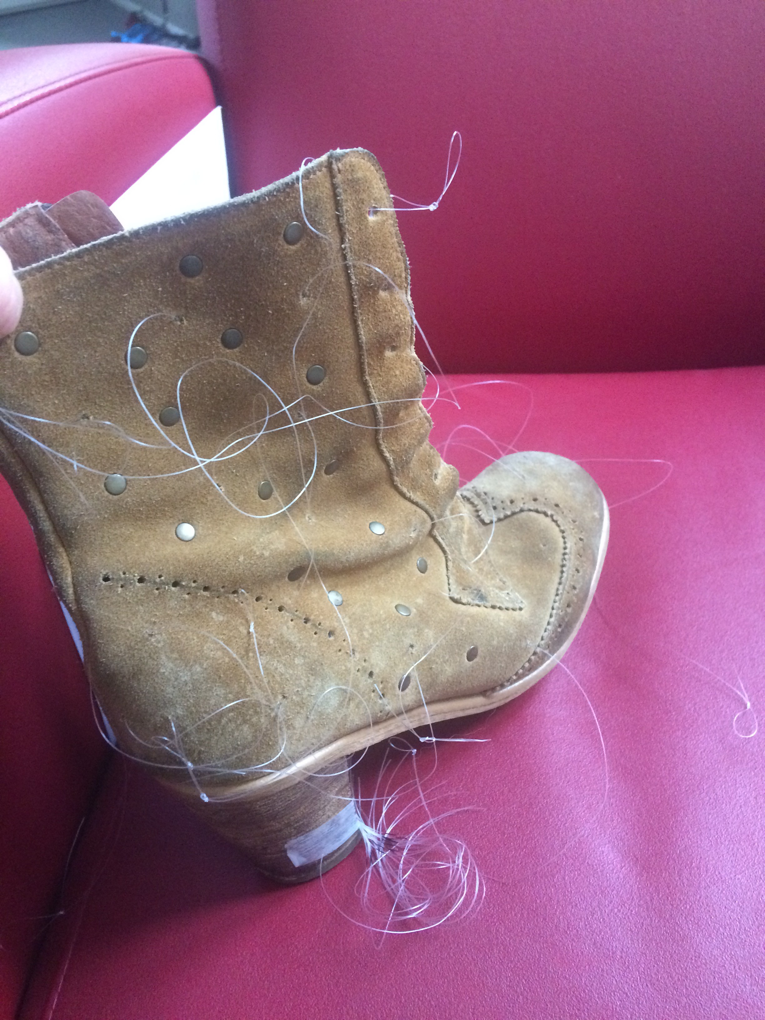
Using needles and pliers I ran a piece of fishing line from each of the leds positions, between the leather and the inner lining, to the heel. This took a lot of effort, and broken needles.
But afterwards I ended up with this:
![]()
And a whole tangle of wires of the other end.
![]()
-
3Prepare the leds
I measured out lengths of 0.1mm enameled copper wire. Folded the wire in the middle and twisted the two parallel wires together. This way you end up with a loop at one end, which is used to pull it through the shoe in the next step. I then soldered a 0805 white led to the other end. I applied a bit of nail varnish to prevent shorts and to strengthen the connection.
![]()
I created different lengths, since there was a nearing deadline, and I was running low on enameled wire. Not ideal.
-
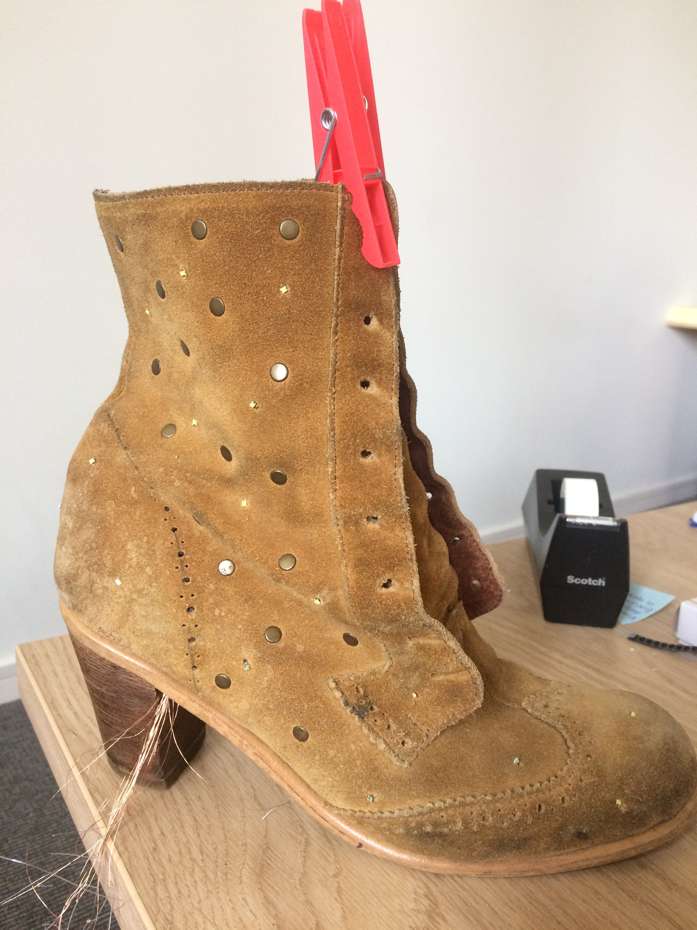
4Pulling the wires
Next I had to pull the wires through the shoes using the fishing wire. I put the fishing wire through the loop in the twisted copper wires added a knot. Then carefully started pulling on the fishing wire on the other end of the shoe. Since, for some leds, it had to go around bend I had a few copper wires break. So I had to start over on those.
I ended up pulling those hard to reach leds, in multiple sections, reducing the amount of force need.
I pulled the wire, till only the led was nicely seated in the hole. I attached the leds using white glue.
![]()
-
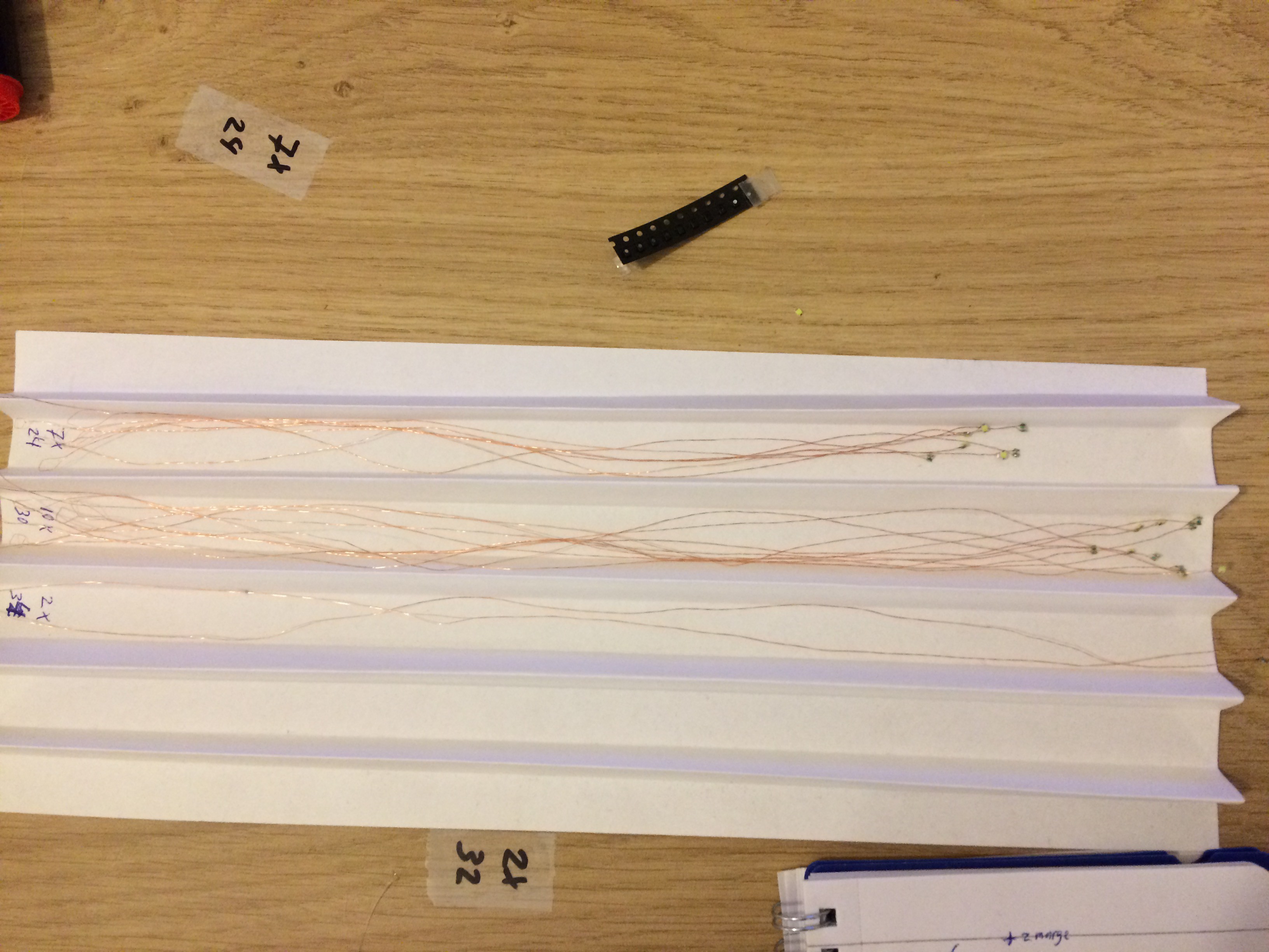
5Sorting out the wires
With 19 pair of wire ending at the heel, you have a whole mess of wires that you have to sort out. Partially unwinding the wires; removing the enamel coating from the ends;
checking which led it's going to; and which wire is the cathode. One led wasn't working, and another I could re-solder in-situ.I first wanted to wire both shoes exactly the same, but this would make a difficult job even harder. So fixed this in software. The only downside is that the two shoes have slightly different software.
I then started grouping wires according to a charlieplex pattern. Twisting the five groups of wires together. I then cut a piece of perfboard with 5x2 holes, added a 5x1 female header, and soldered the groups of wires to the header. (sorry, no photos of this stressful step)
Always testing the leds at each step.
But then, with a simple Arduino sketch, we got first light:
![]()
-
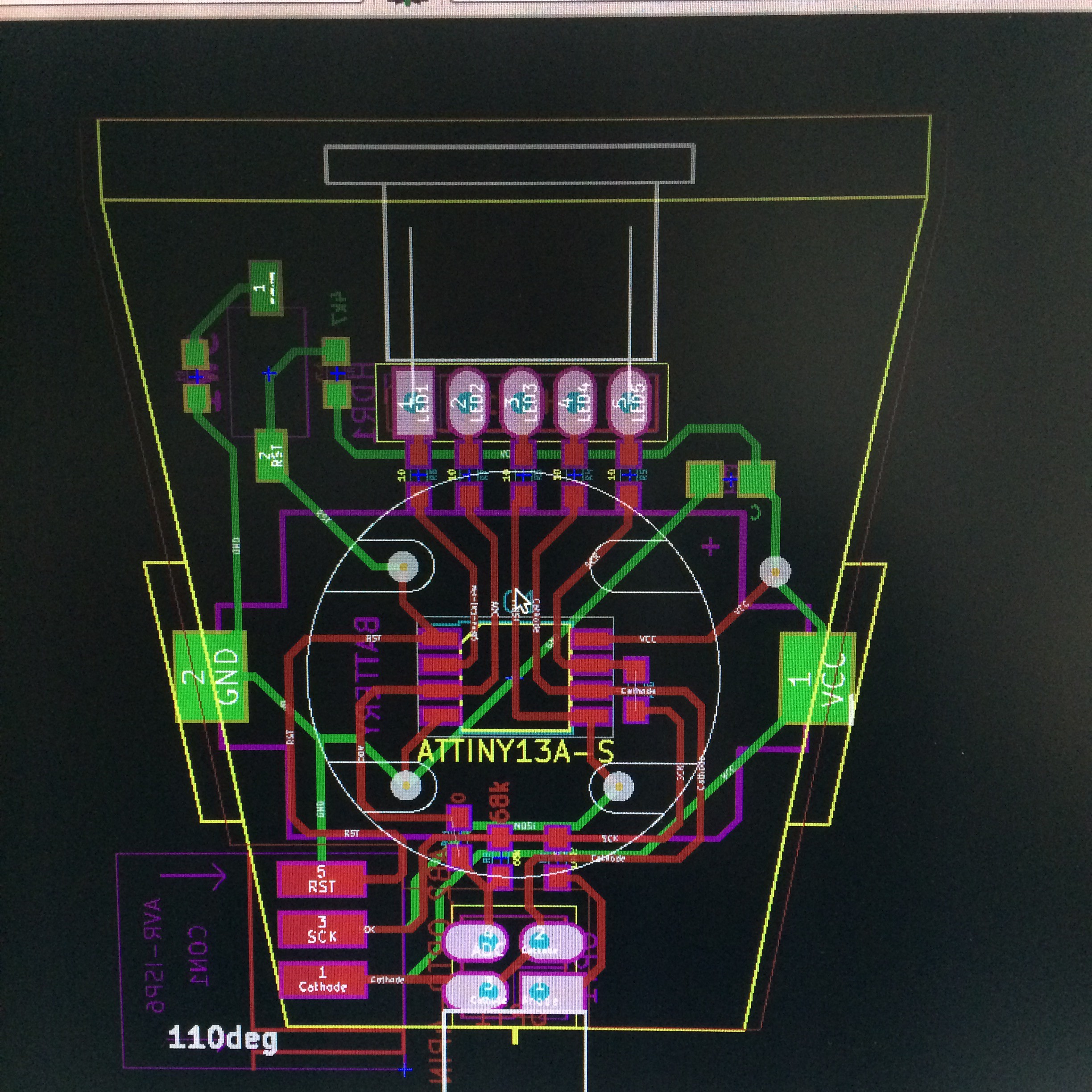
6Creating the PCB
I didn't have a lot of space on the heel, so I designed my own tiny PCB.
![]()
Since there is no space for a 3x2 ISP header, I'm using a diy card edge connector. I pulled out the odd spring clips from a shortened PCI connector, so I'd still have a 0.1" pitch. That way you could still attach some 3x2 male headers, by sliding the PCB between the headers, and soldering them from the SMD style (I hope that makes sense, otherwise let me know)
I printed the design on transparencies; exposed the design on presensitized copper clad; develop them; etched them. I then added soldermask paint; exposed the soldermask design; removed the unhardened paint. Using a dremel with a disk, I cut away the excess FR4, and shaped the PCB.
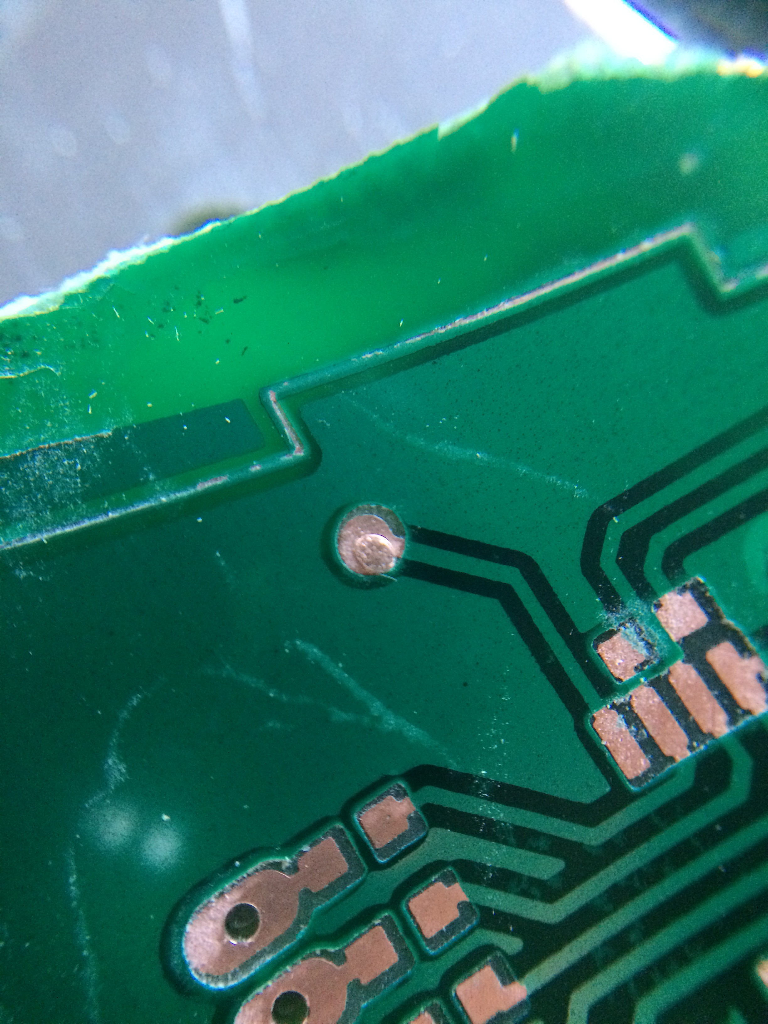
I made the vias with my new DIY rivet technique.
![]()
(PS notice how the vias underneath the battery holder are where there is a cutout in the plastic of the holder. That way the battery holder can sit flat on the PCB)
-
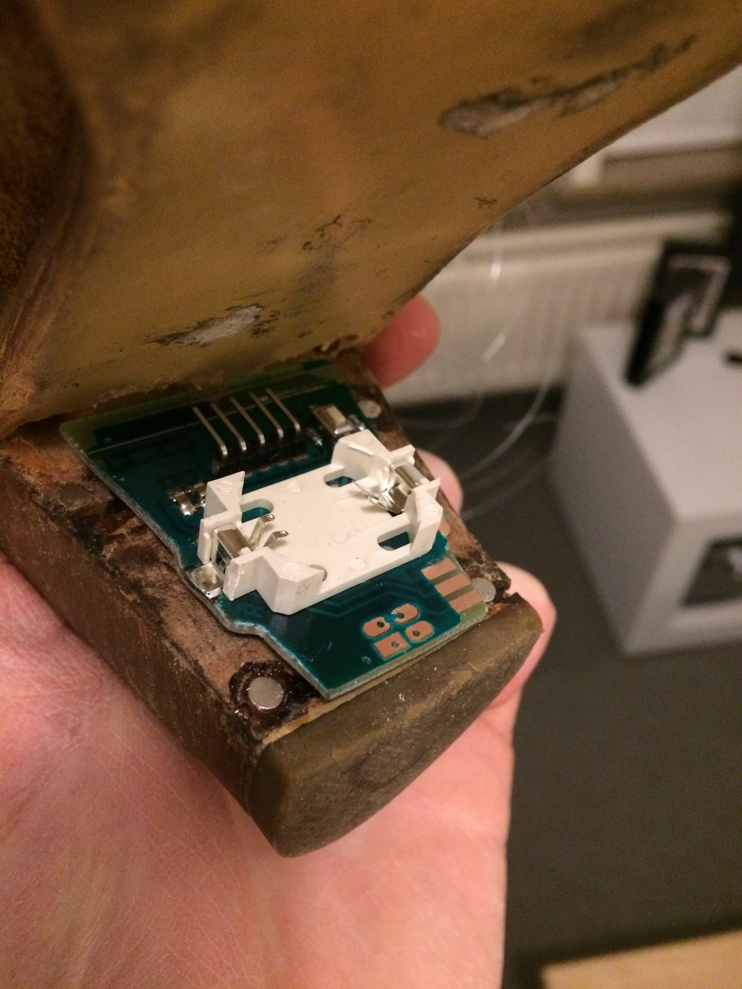
7Miscellaneous
I soldered all the components to the PCB. I bend the leads of the CNY70, so the sensor would point parallel to the board (towards to ground). That's when I noticed the optical reflective sensors interfered with the programmer! I soldered in two wires with one male and one female end, so I could disconnect the sensor during programming, and reconnect afterwards.
![]()
I made two lids, that would sit over the PCB, with a hole in the bottom for the reflective sensor to poke through. These lids would attach with magnets to the heel (so one could replace the batteries). I painted them the same color as the heel.
I drilled four holes in the heel, and glued in magnets.
I made a small recess in the heel, so the SOIC8 on the underside of the PCB would stick out in this recess, resulting in a lower profile. Otherwise the already made lids wouldn't fit.
I dremmeled away some of the sole, so I could glue in the female header attached to the perfboard from step 5. After that you could just slide the PCB in and out. The friction from the header was enough to hold the PCB in place. For good measure, I added some double sided foam tape in the end.
Due to the deadline, I don't have any photo's of the finished PCB in place.

Discussions
Become a Hackaday.io Member
Create an account to leave a comment. Already have an account? Log In.
>The only downside is that the two shoes have slightly different software.
And I thought the espresso machine at my old job made excessive use of electronics.
Nice build though, my SO would want these. The way you inset the LED's into the leather looks really good.
Are you sure? yes | no
Nice project
Are you sure? yes | no
Nice job!
Are you sure? yes | no