-
1Basic bluetooth keyboard
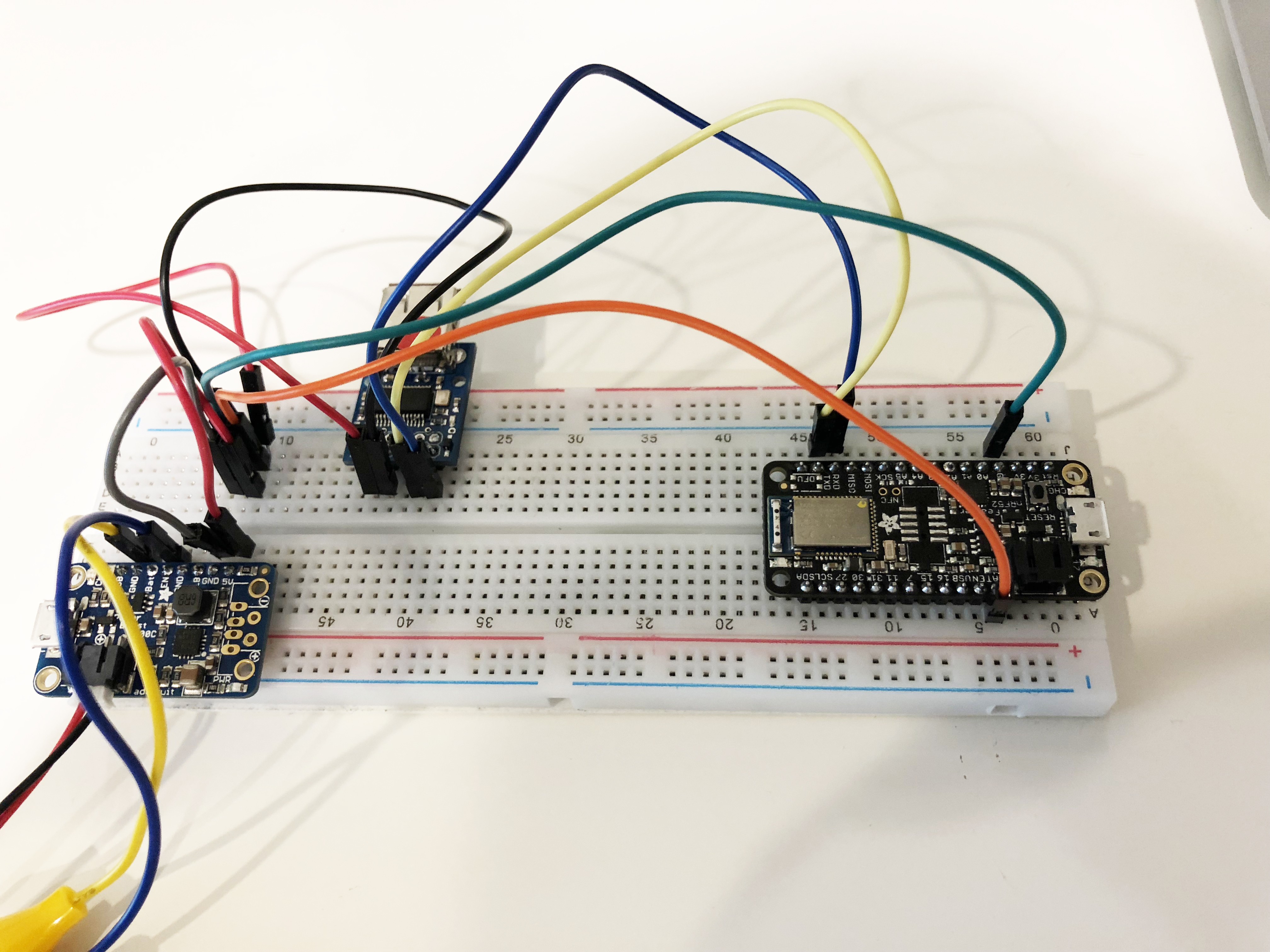
Parts you'll need to connect to make the keyboard bluetooth. This doesn't include the power button's LED.
- Solder male headers onto each module
- Connect the pins as follows:
- Power Boost 5v -> USB Host 5v
- Power Boost GND -> USB Host 0v
- USB Host TX -> nRF52 RX
- USB Host RX -> nRF52 TX
- Power Boost Bat -> nRF52 Bat
- Power Boost GND -> nRF52 GND
- Power Boost GND -> On/Off Button 'C'
- Power Boost EN -> On/Off Button 'NC'
- Connect any size LiPo battery with JST-PH connector to the Power Boost 500.
![]()
We need the Power Boost to convert the 3.7v from the battery into 5v because that's what USB devices require.
-
2Setup Arduino IDE
Before you can start uploading your own code (firmware) to the nRF52, you'll need to setup the Arduino IDE.
Adafruit has already written a pretty comprehensive guide so I'm not going to repeat it here.
Make sure you complete this step and uploading an example code like Blink works before you move on to the next step!
-
3Upload code to your nRF52 Feather
- Clone or download my repo off github
- Open the file NRF52Keyboard/NRF52keyboard.ino
- Try compile in Arduino IDE (check mark)
- Hit upload with the nRF52 Feather connected
-
4Try out your new wireless keyboard
After uploading and plugging back your nRF52 feather, it should show up as a bluetooth keyboard, ready to be paired.
- Pair your keyboard from your computer's bluetooth. It should show up as "Kinesis Advantage 2" - You can change this name from NRF52Keyboard/bluetooth.cpp file.
- Connect your keyboard USB to the USB Host
And everything should now work, wirelessly!If you're happy with just a bluetooth keyboard without a power status LED, you can just stop here and skip to the section about fitting everything inside the Kinesis. I probably would have if I knew how much more complicated it would get before getting the idea in my head that an LED would be cool.
-
5Reading pin voltages
Ok, now we want to figure out the power states of our keyboard:
- Power On - normal battery
- Power On - low battery
- Power Off - Charging
- Power Off - Battery Full
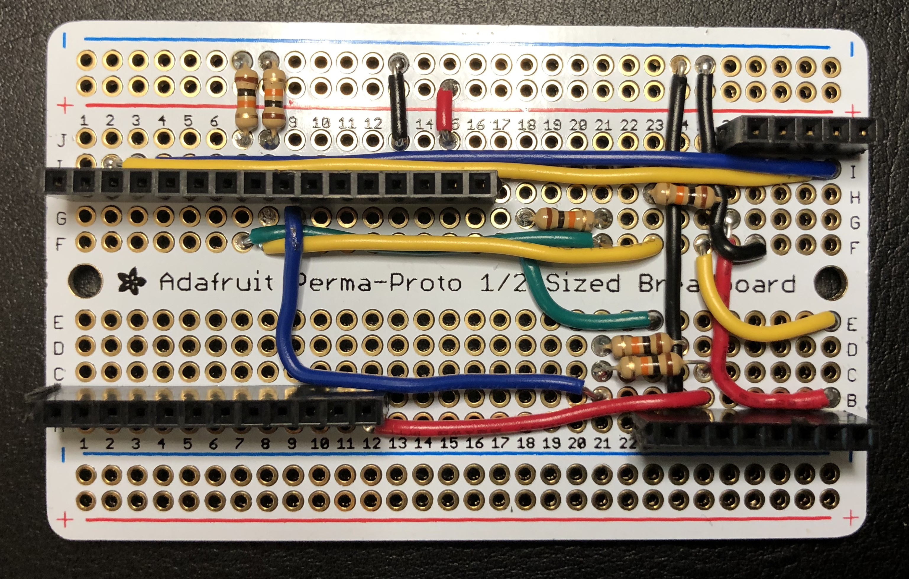
So you'll need to read the BAT and USB pins on the Power Boost using the NRF52 ADC pins.The 5V pin on the Power Boost can be read using an Analog or Digital pin.
Here are the pins I used:
  #define BAT_PIN                  (A3)
  #define FIVE_VOLT_PIN            (A4)
  #define USB_PIN                  (A5)
Wire the 5V pin with a 10k pulldown resistor as we'll just be digital reading this.
I wired the USB pin with a pulldown too as I originally thought reading the BAT voltage was enough to tell whether the battery was still charging.
You'll need to divide the voltage for all 3 pins as the nRF52 is 3.3v.
![]()
If you want to know how voltages are read or teach me a better way of doing it, look at the NRF52Keyboard/power.cpp file as well as the NRF52Keyboard/NRF52keyboard.ino to see the voltage values used to determine battery status.
-
6Connect the RGB Led
- Connect the LED Anode to the nRF52 3.3v Pin (I connected this pin to the perf board's power rail)
- Connect the RGB pins each to a different pin on the nRF52. Here are the pins I used:
  #define BUTTON_RED_PIN    (A0)
  #define BUTTON_GREEN_PIN  (A1)
  #define BUTTON_BLUE_PIN   (A2)
Adding resistors for each LED
I've since added resistors in-line to each LED. These are needed to get mixed colors as each LED has different forward voltages.
- Red = 330ohm
- Green = 100ohm
- Blue = 47 ohm
-
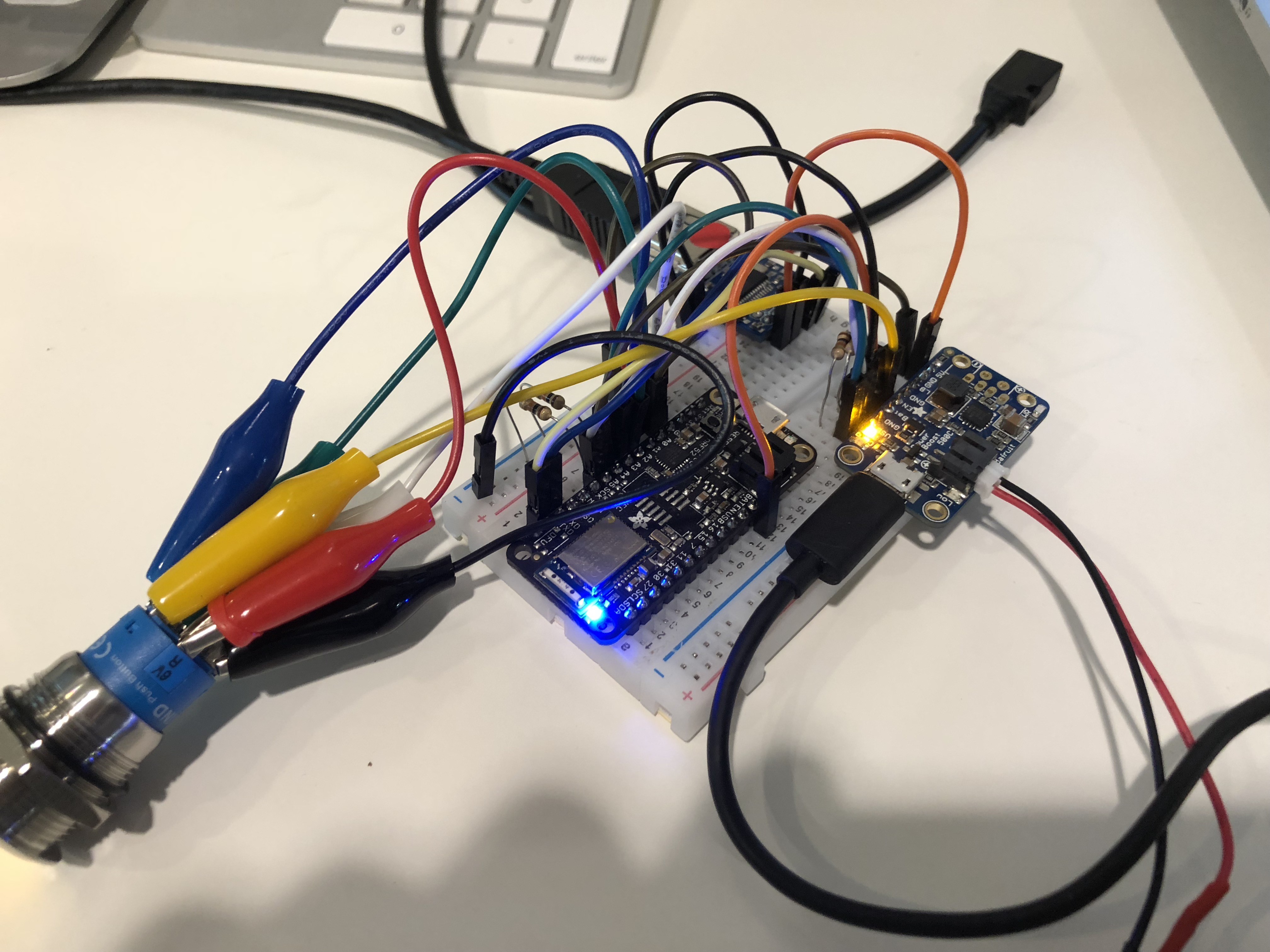
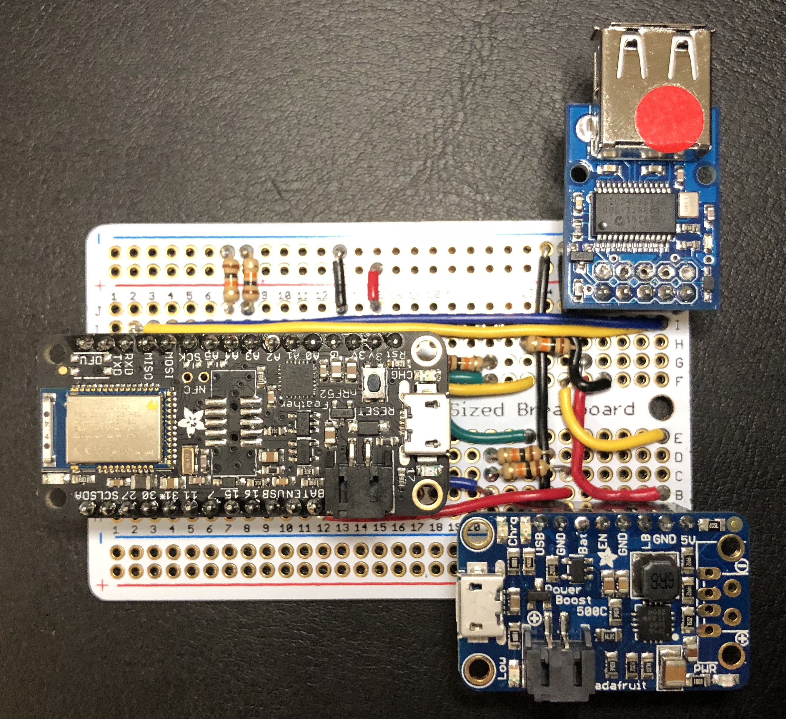
7Fitting it in the Kinesis case - Move everything onto the Perma-Proto Perf Board
Solder all the components down, with female headers and solid core wire.
If you solder the boards directly without female headers, you won't be able to detach them. This will be a problem because you can't upload code onto the nRF52 without disconnecting it from the USB Host serial.
Parts on breadboard
![]()
Parts on perfboard (without LED wires soldered in yet)
![]()
-
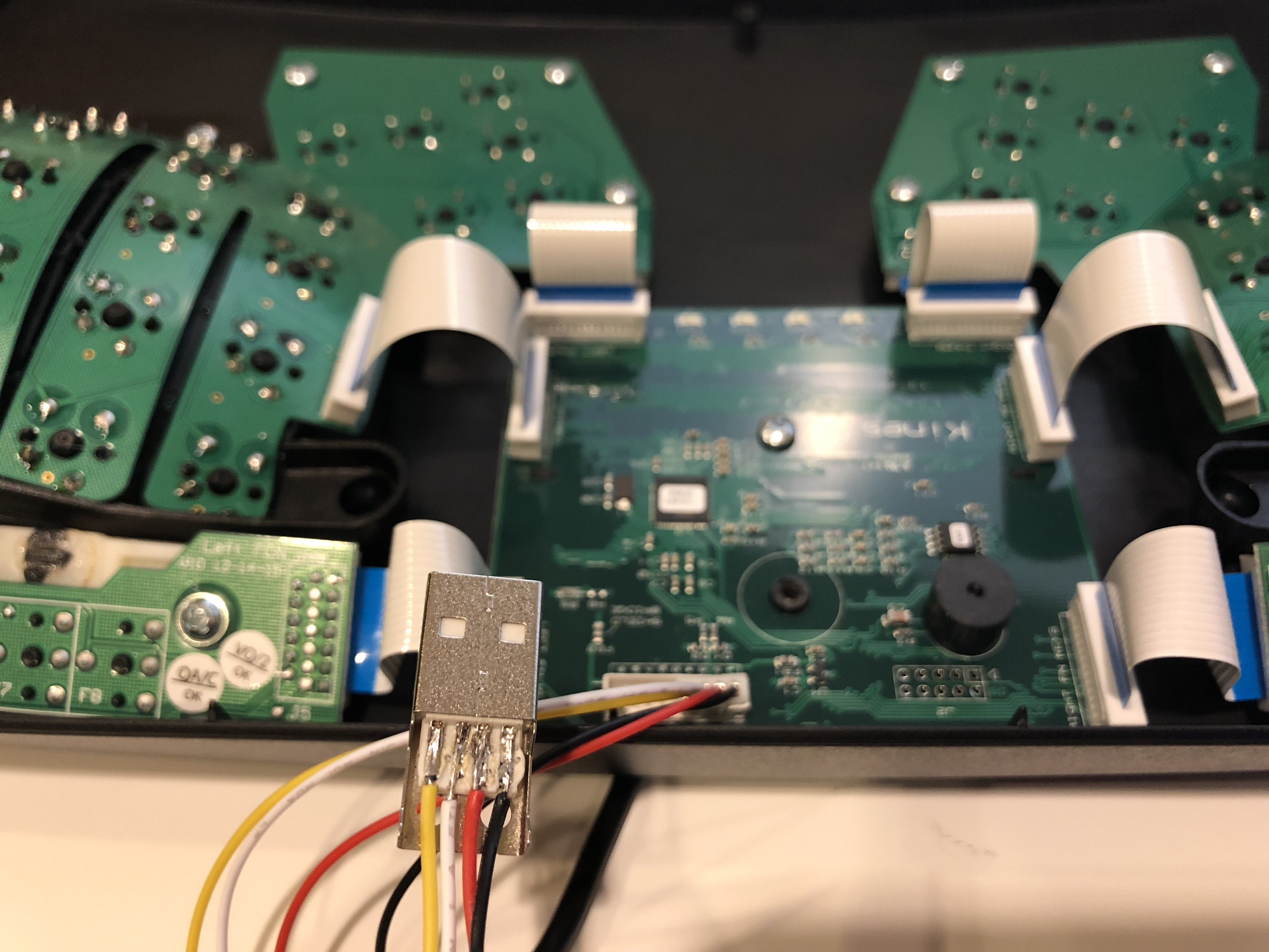
8Fitting it in the Kinesis case - USB Cable
We need to make our own USB cable that connects to the Kinesis controller because the stock one is huge. It's straight forward, but make sure you don't have stray wires that short the USB cable. It took a while to debug this so use a multimeter to check for continuity.
![]()
-
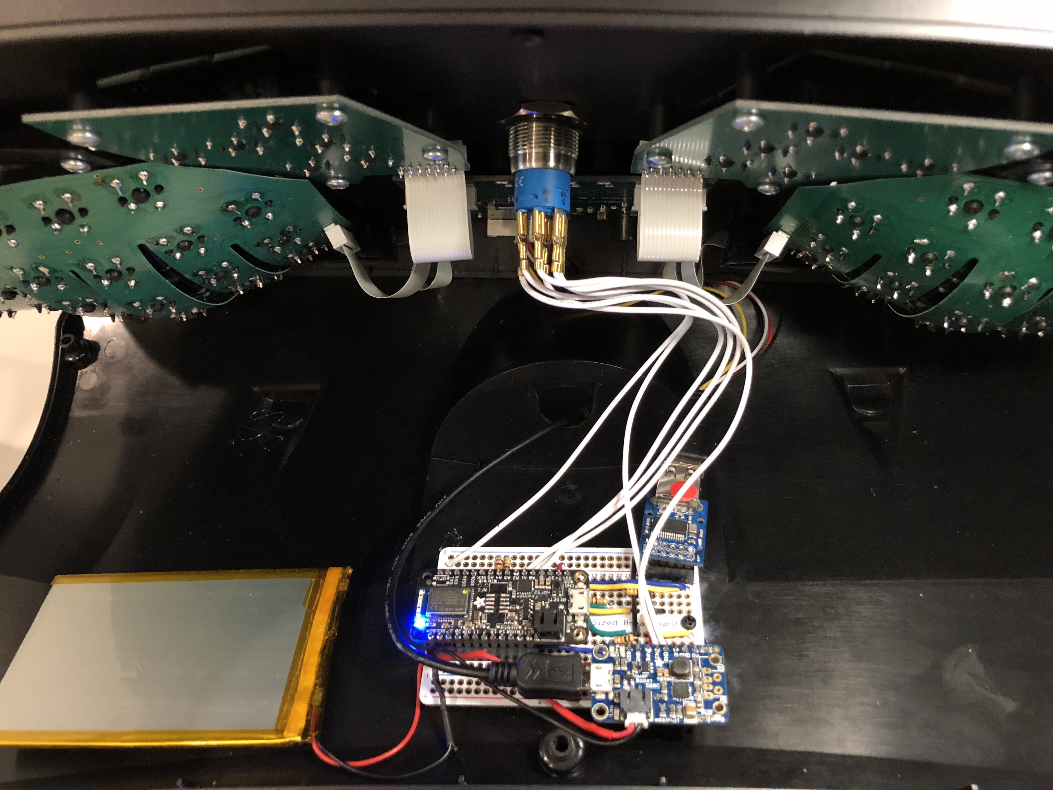
9Fitting it in the Kinesis case - Power Button
The point of no return. Drill a 19mm hole in the middle of your very very expensive keyboard.
![]()
-
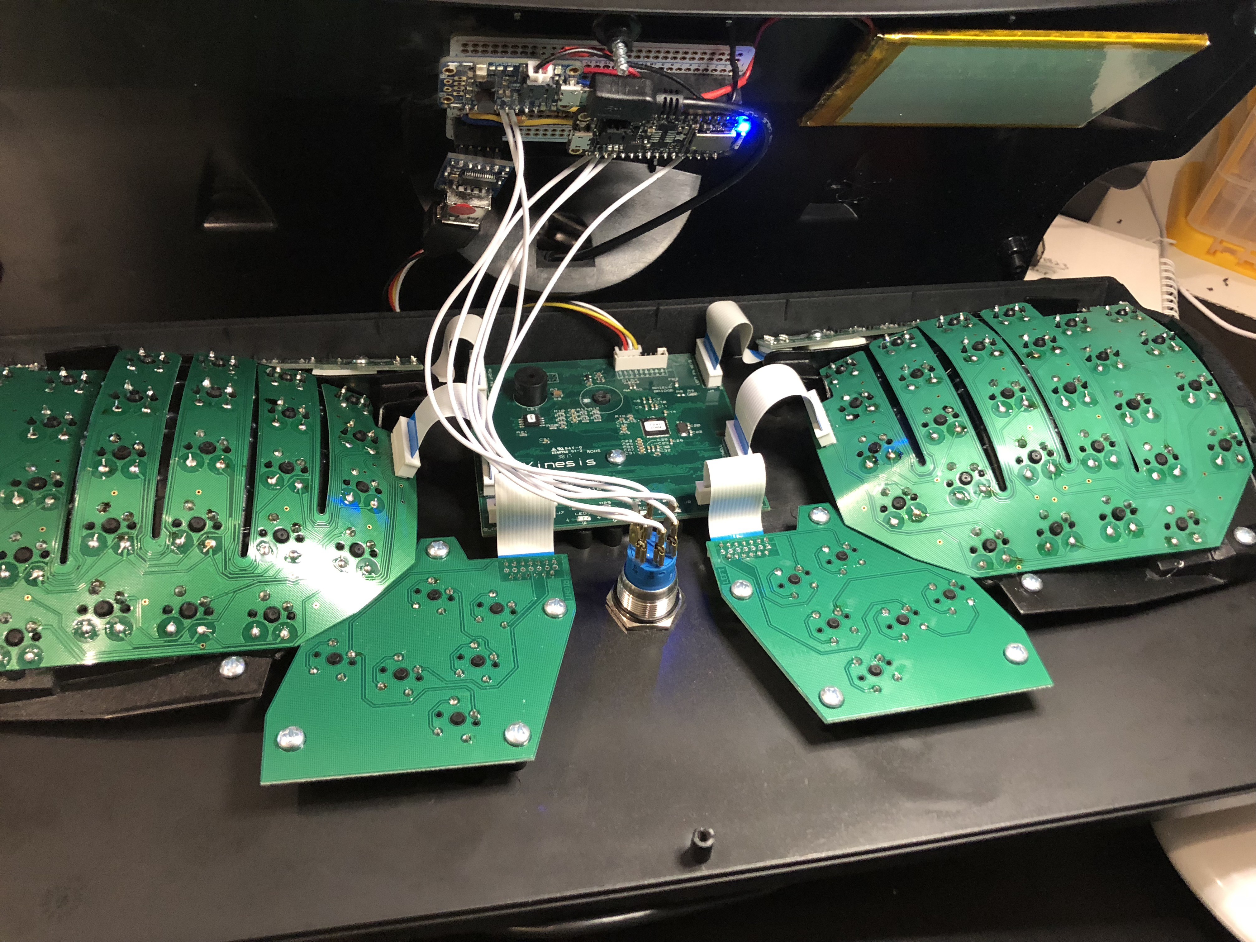
10Fitting it in the Kinesis case - Putting it together
- Tape the battery in place. I used velcro tape here so the battery could be removable.
- Epoxy down the M2.5 standoffs. I tried sugru, super glue, tape and drilling. Just epoxy them down and be done with it. You'll want to position your board off-center so that the USB plug has space. I didn't, so my USB host pins are a little bent.
- If you're thinking of soldering another battery in parallel on the other side - don't! I did it originally until I found out it could be dangerous.
![]()
![]()
Wireless BLE Kinesis Advantage Keyboard (USB Host)
Drill and hack that $300 keyboard because wires shouldn't exist in 2018.
Discussions
Become a Hackaday.io Member
Create an account to leave a comment. Already have an account? Log In.