Morning.Star
-
Clumsy Me
09/26/2018 at 22:58 • 4 commentsOops, I broke it in half again.
@salec commented that I was single-tentacly creating a new Moore's Law for LED Cubes.
Hehe, he has a point. Luckily though, with the next generation of 0201s thats as far as it goes. Its highly doubtful discretes will ever get any smaller and still be available to hackers...
First up, I managed to avoid the problems I was having with insulation by changing the wiring sequence. This was only possible by gluing the LEDs, although I think I can make a jig for that too, and go back to metal tape.
These LEDs are the same size as the legs of regular components. Very easy to make a castellated bar to wrap the wires on, all identical.
![]()
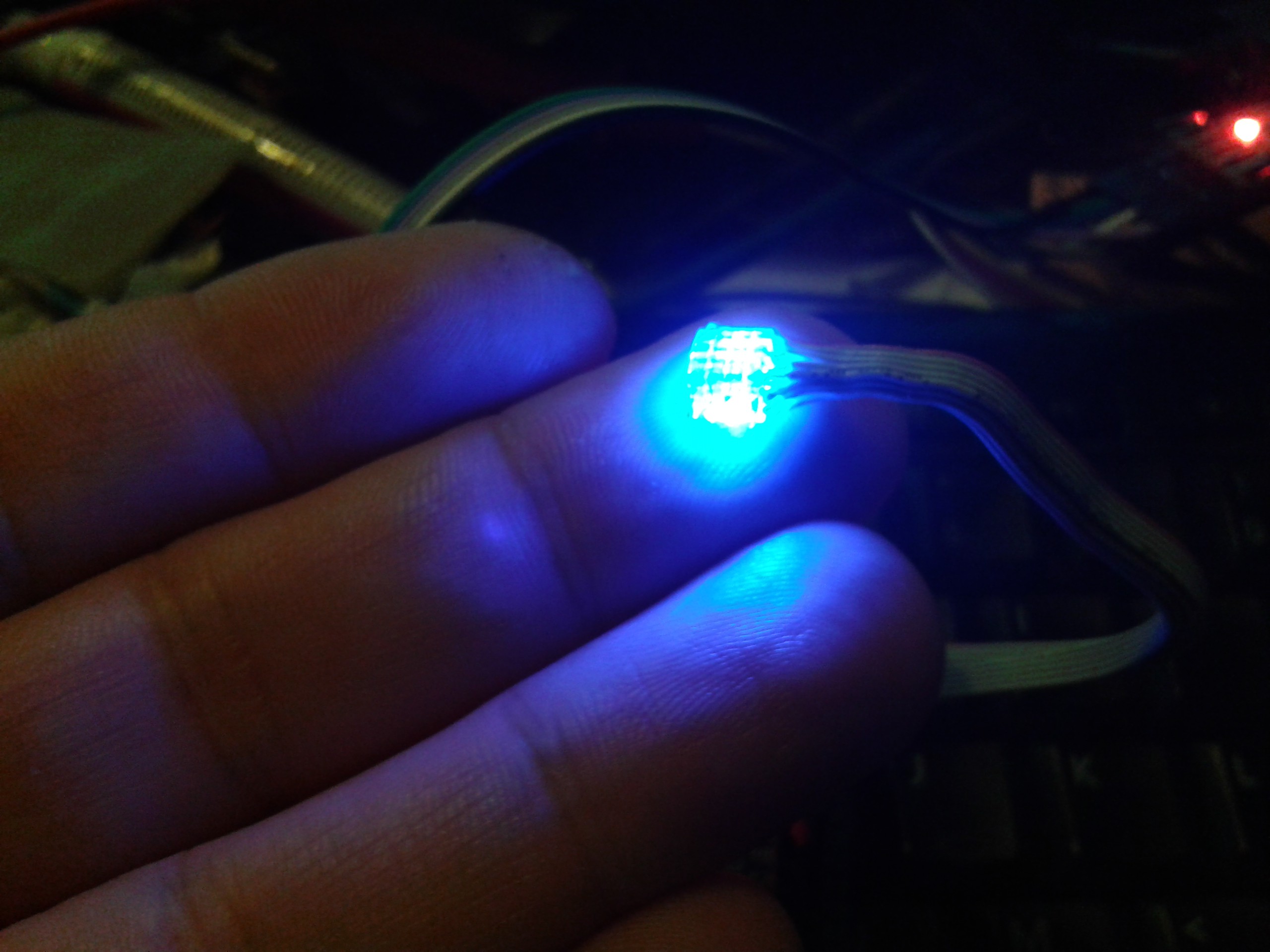
I ran out of red LEDs to complete a cube with, these really do not like to be messed with and die with little provocation. They are one-shot. So I switched to the blue, and printed out a motivational template.
![]()
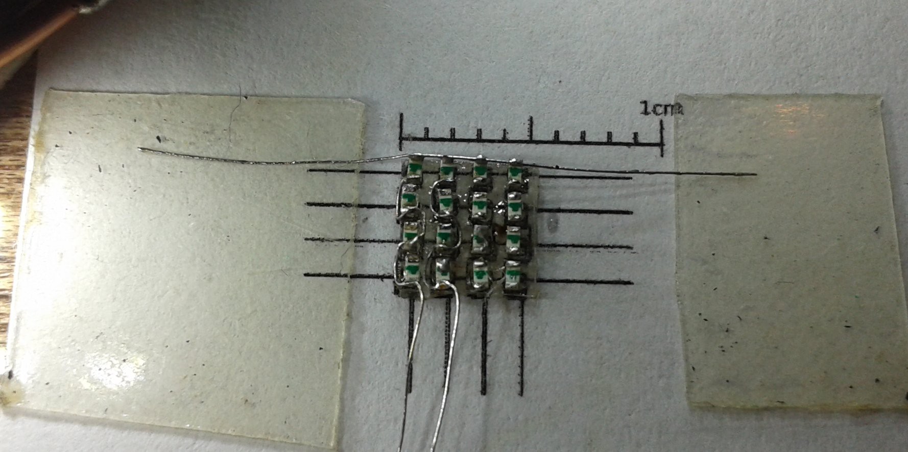
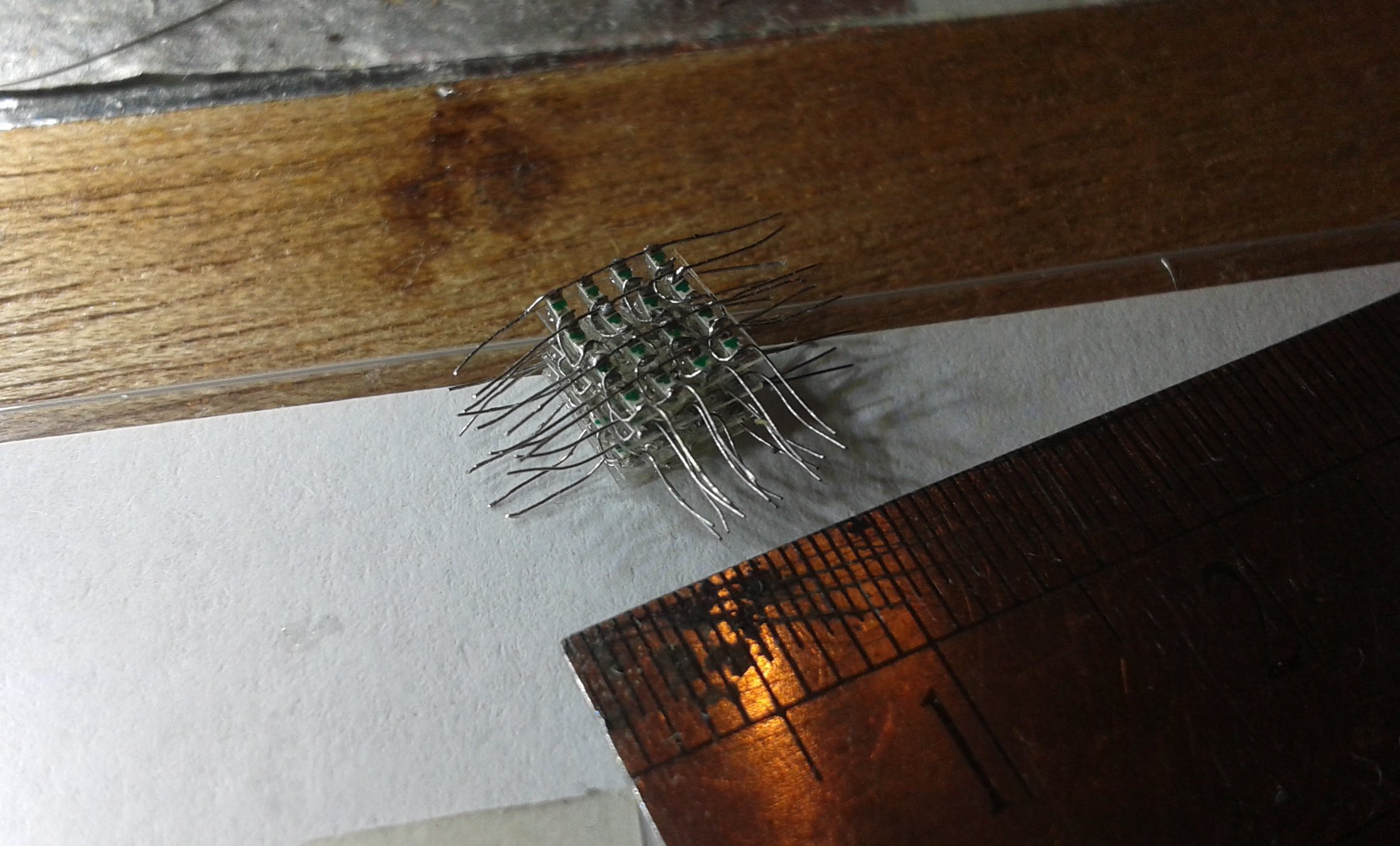
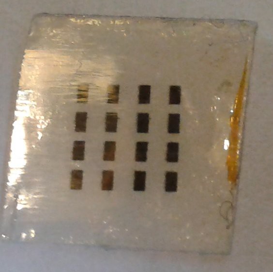
The electronics measure 4.5mm, but its sat on a 5mm chip of plastic as a bearer.
26 pieces, 5x5.
![]()
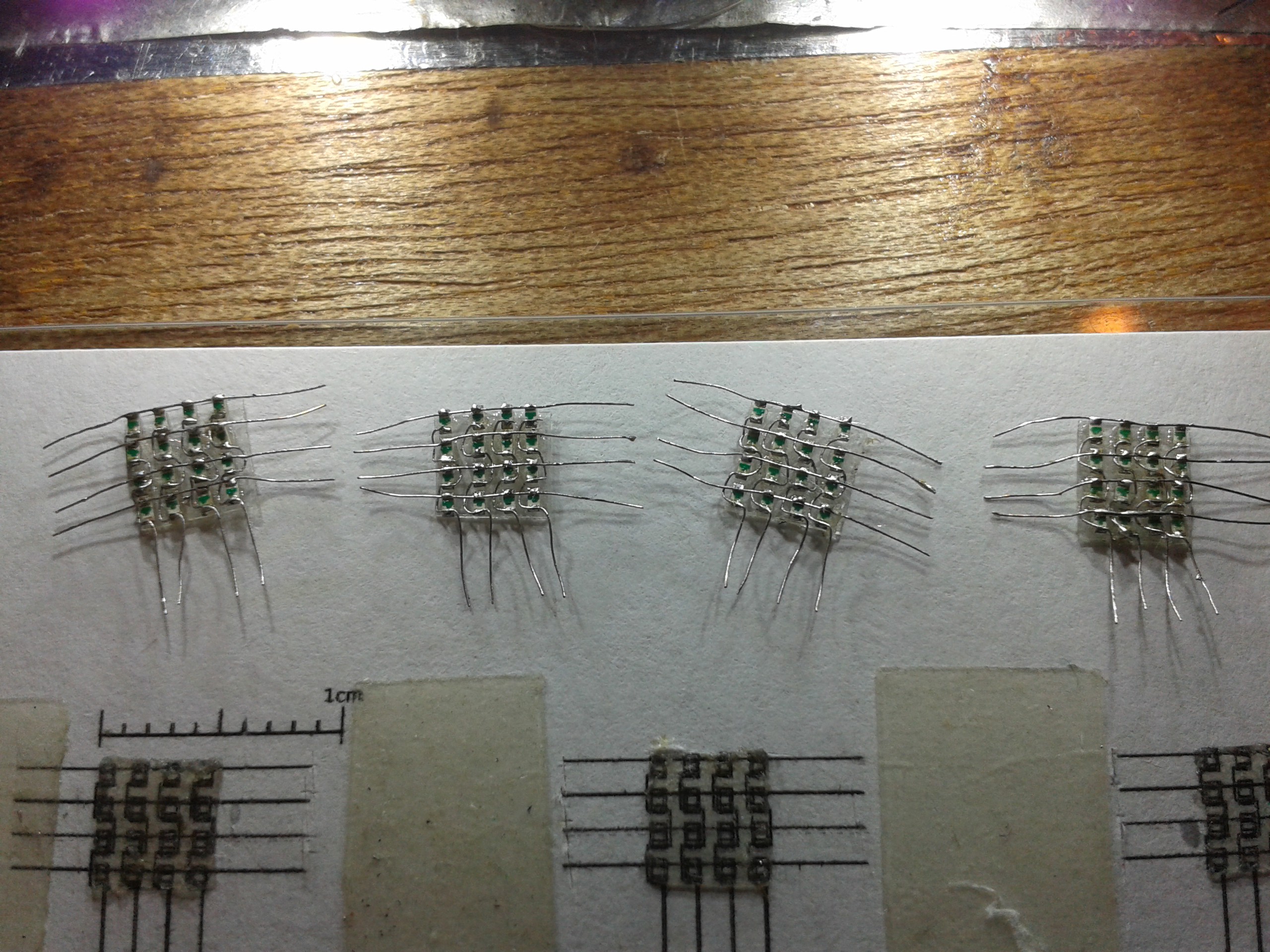
I'm going to be doing these in my sleep soon.
![]()
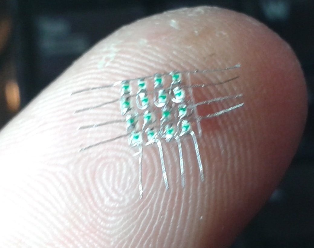
Still 5mm, still cant believe I managed it..
![]()
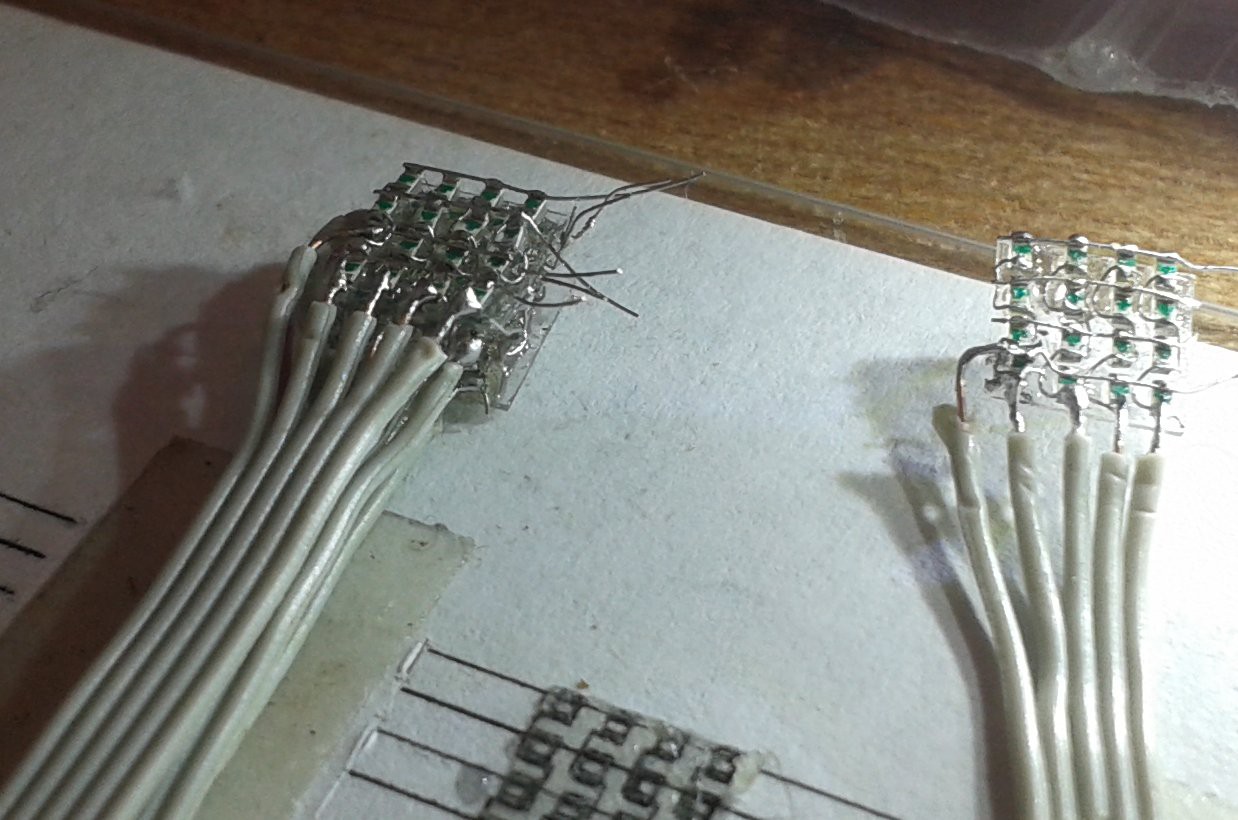
I scratched my head trying to think of an easy way to cable these, and then remembered a piece of PATA EIDE cable. It has 80 cores in the space of 40, and they are solid copper. Perfect...
Gluing , stacking, stitching the layers together.
![]()
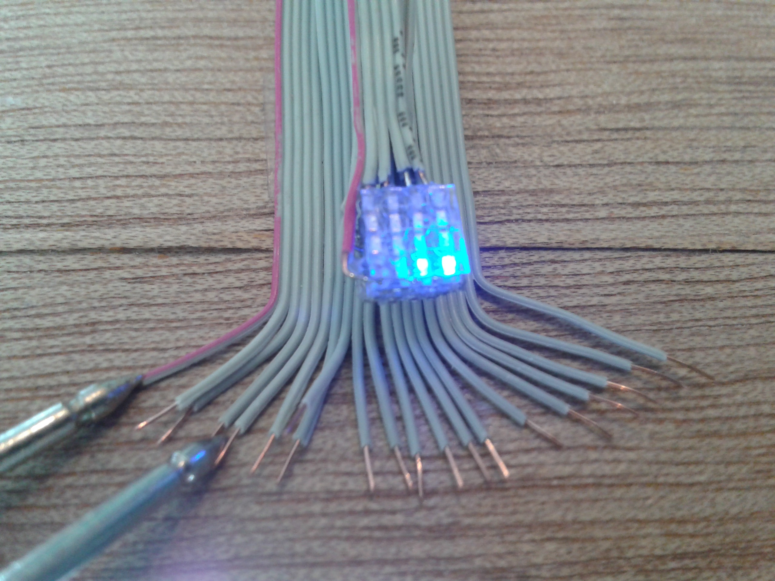
Testing... All still 100% perfect, I've been doing this every step to avoid finding a short when its too late.
Typically, the very last solder joint bridged. Maybe I was getting excited. Maybe its just a pain in the ass. I dunno, but this always happens. It wouldnt shift, and eventually the LED fell out. So I pulled the wires out straight, held the LED in tweezers and bravely soldered the anode to the crosswire and pushed it back, then folded the cathode wire back and beaded them.
One is now slightly conky, in the bottom back left corner. I know its there... OK so its 98.4375% perfect, dammit. ;-p
![]()
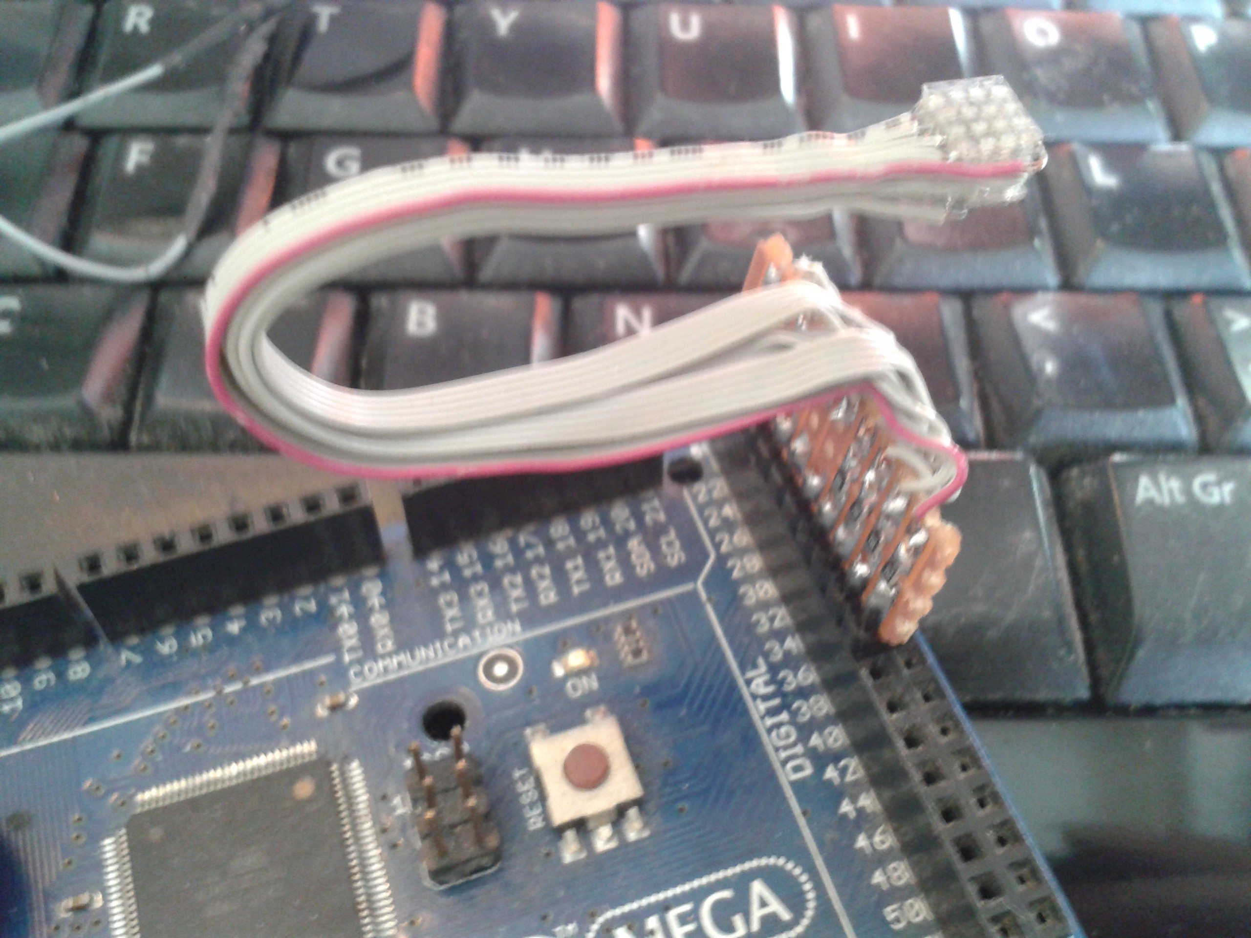
I found some series resistors and fitted a pin header for the Mega.
![]()
But unfortunately it wont program and I dont know why... I'll get to the bottom of it.
![]()
It still nearly works correctly. There's already a propeller sketch inside the Mega for the previous cube, but the wiring's different.
![]()
I got a bit of video, I'll crack it tomorrow.Kind of working. The software isnt yet, but thats still a record. :-D
-
NanoBugging
09/23/2018 at 07:38 • 0 commentsWell.
The 0402 LEDs duly turned up in time for a weekend of burning the tip of my nose, Welder's Flu and another attempt at the world record for Extreme Cussing. ;-)
![]()
First off, I decided to dispense with my usual have-a-go attitude and built a decent workstation. After the 0805 LEDs gave me neck ache hunched over a desk I put a box on my knees and rested a board on it so it was inches from my face. Much more comfortable...
Its tempting to clear a space in front of you at a table with decent daylight for this.
You will be mistaken. ;-) Firstly, you wont be able to see a thing without magnification, and a table magnifier seems like a good idea. That actually makes it harder, because you are working at arms length and while you can see the movements you are making they are hard to control. Fine work like this requires both hands rested on the work-surface, and that so much easier in front of your face.
![]()
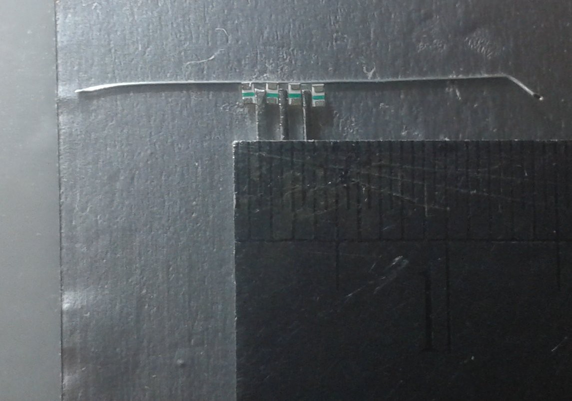
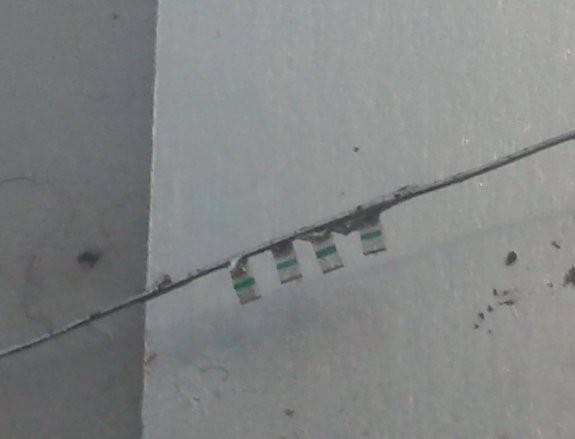
Light is also an issue. Decent daylight throws shadows, and at this scale things vanish in them way too easily, plus these contacts are 0.25mm wide. Nearly invisible without contrast...
So I modified my jewellers loupe with a set of LEDs that dont throw massive shadows where I can see them. The do throw them, but they are always behind what I'm looking at, out of the way.
![]()
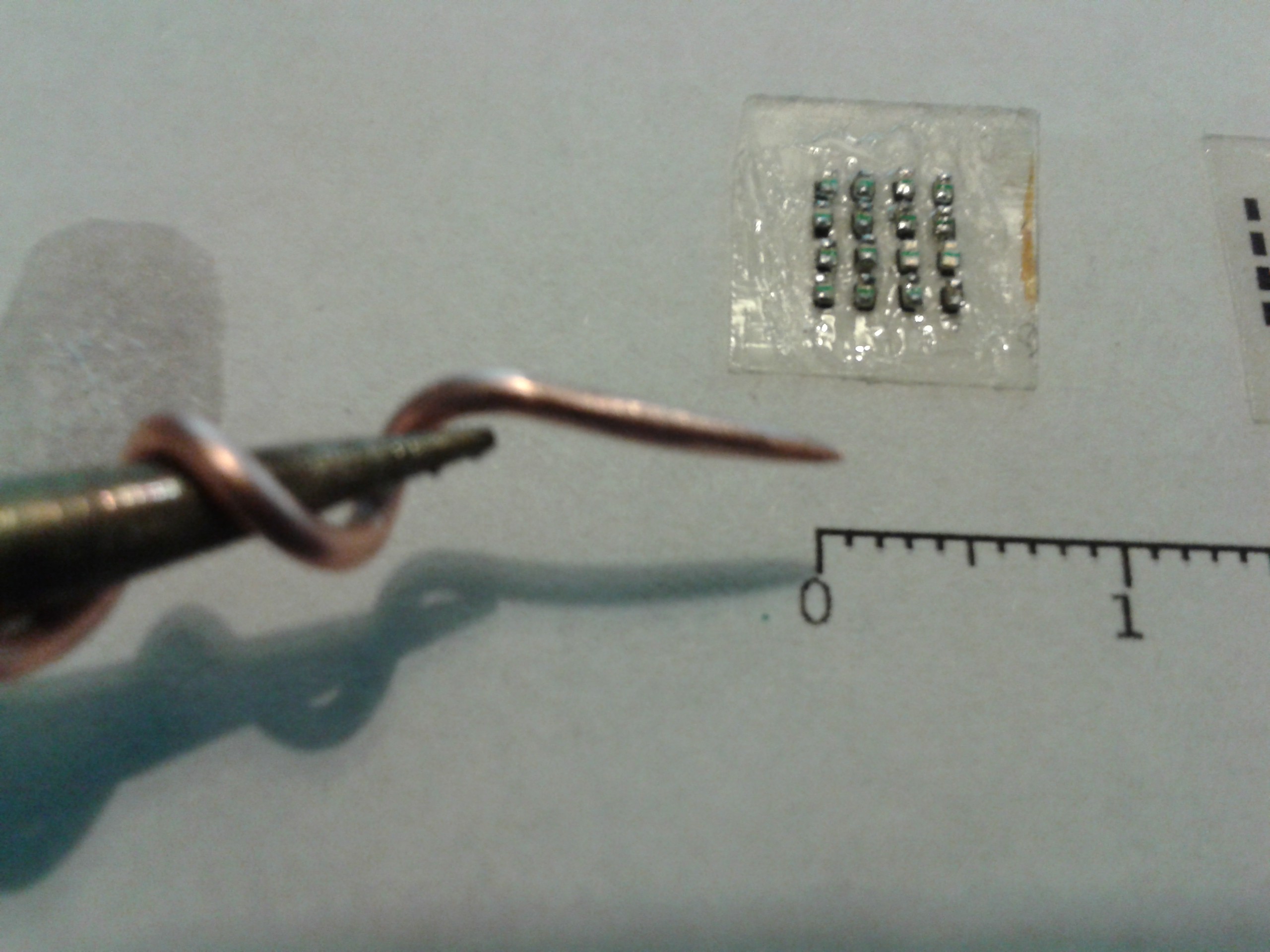
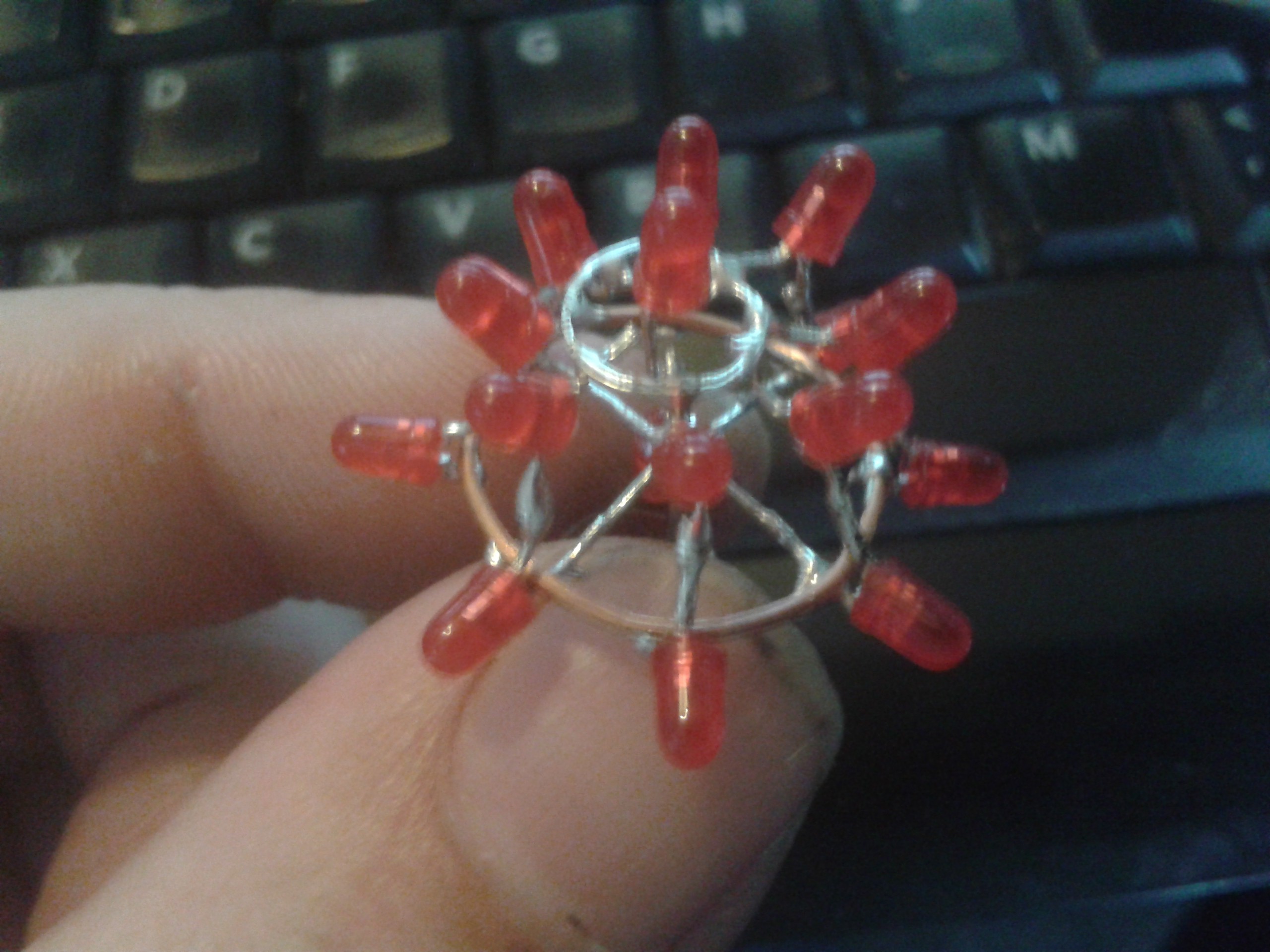
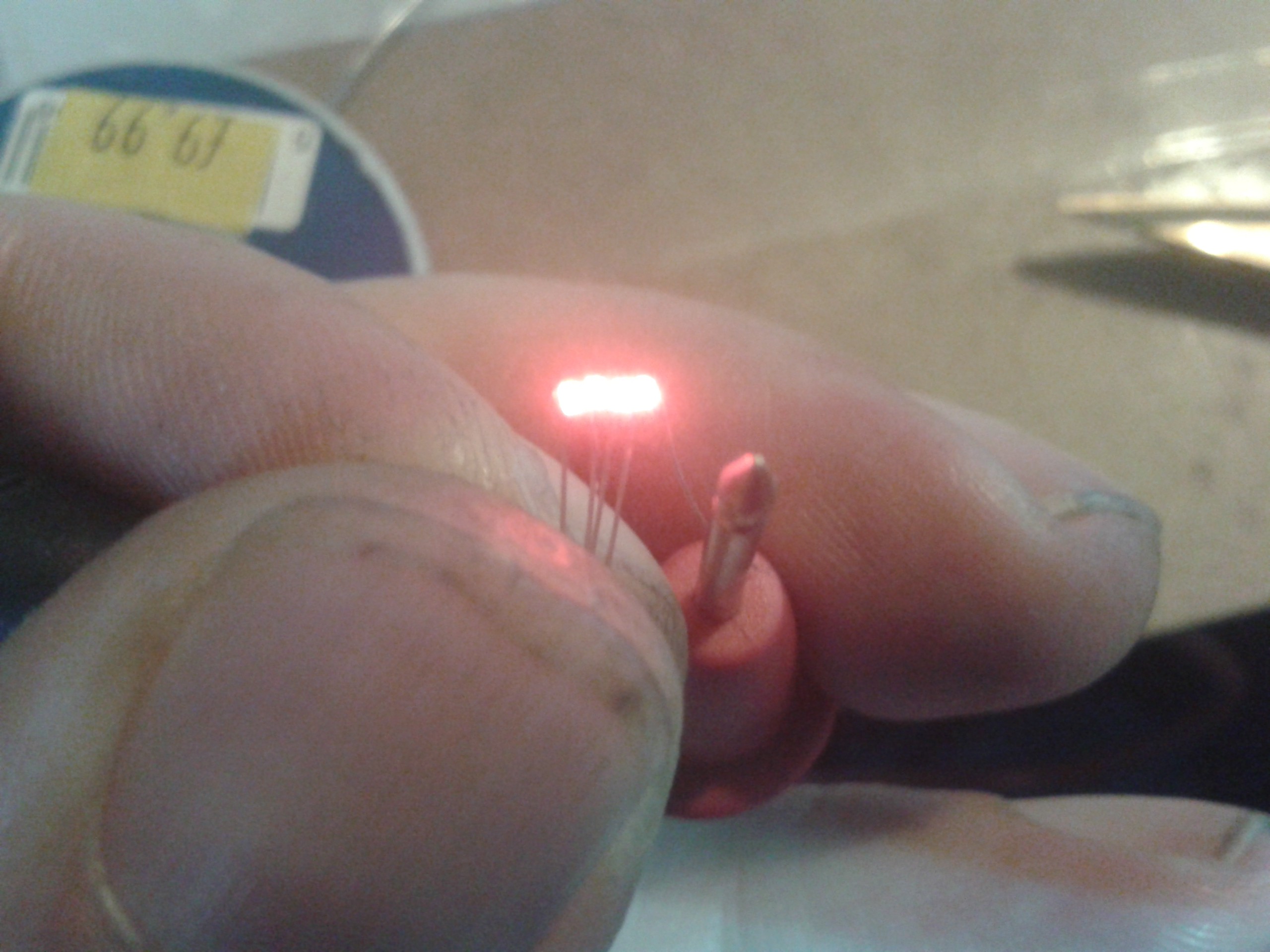
The next task, try and line up these fresh little pips.
Oh, thats handy. They are the same width as the wires cut from these 3mm LEDs. Thats a spherical 3x3x3 cube, its the head for my Angry Snowman. More on him later, I was fiddling while waiting for the 0402s.
![]()
I can use them to line up the LEDs while I roll the anode wire onto them with the soldering iron. While its hot, the wire slides on the glue, and as soon as it touches the tinned LEDs its on there.
Arrrgh, 4mm wide. This is going to break my own goal of 5x5x5mm...
![]()
But I'm not happy with that at all.
![]()
They wont keep still no matter what I do. The guides do keep them in place, but there is enough play that they rattle, sit up on their ends and generally take the piss.
Pity, because this works really well for handling the little devils dry.
![]()
0805 for scale. I dont have any bananas handy.Thus inspired, I decided to have at it micro style, and built first a jig to hold them steady, and then a full micro-vise which clamped them all together and held the ends down to stop them rocking.
![]()
Awww, commented @Stuart Longland , You've put the little baby LEDs to bed.
Hehehe, yeah I thought so too. I added a guide to hold the wire in the right place, and thought I had this sewn up like a Singer factory.
![]()
Muahahahah! Tidy and beautiful, just 4mm across and all works. This is going to be too easy I told myself.
![]()
Until I tried to solder them together.
I could not bring myself to photograph the resulting mess. You plain cannot touch those wires with the iron or all the LEDs fall off it. There was no way I could build a grid with these.
Time for a rethink then.
![]()
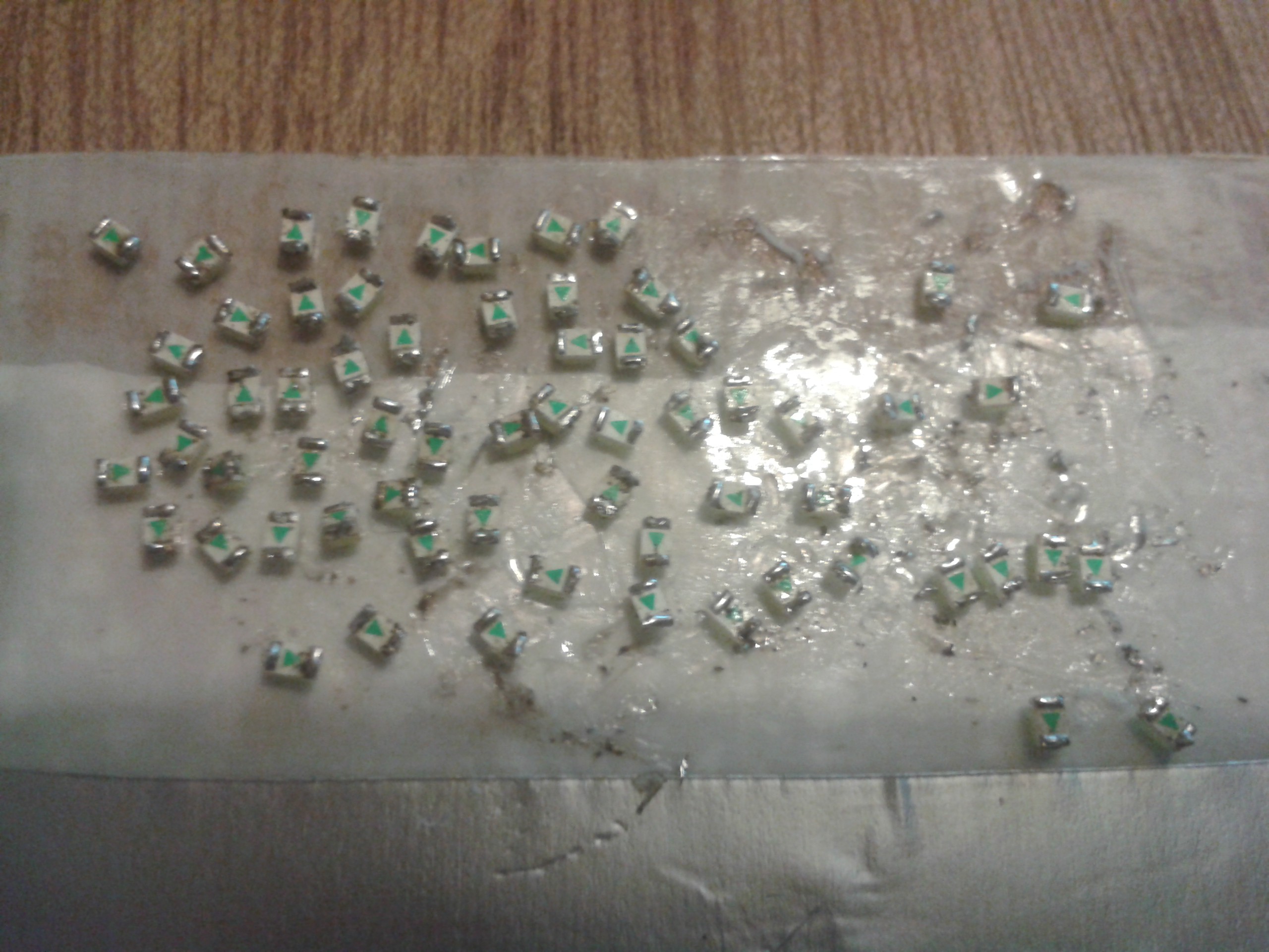
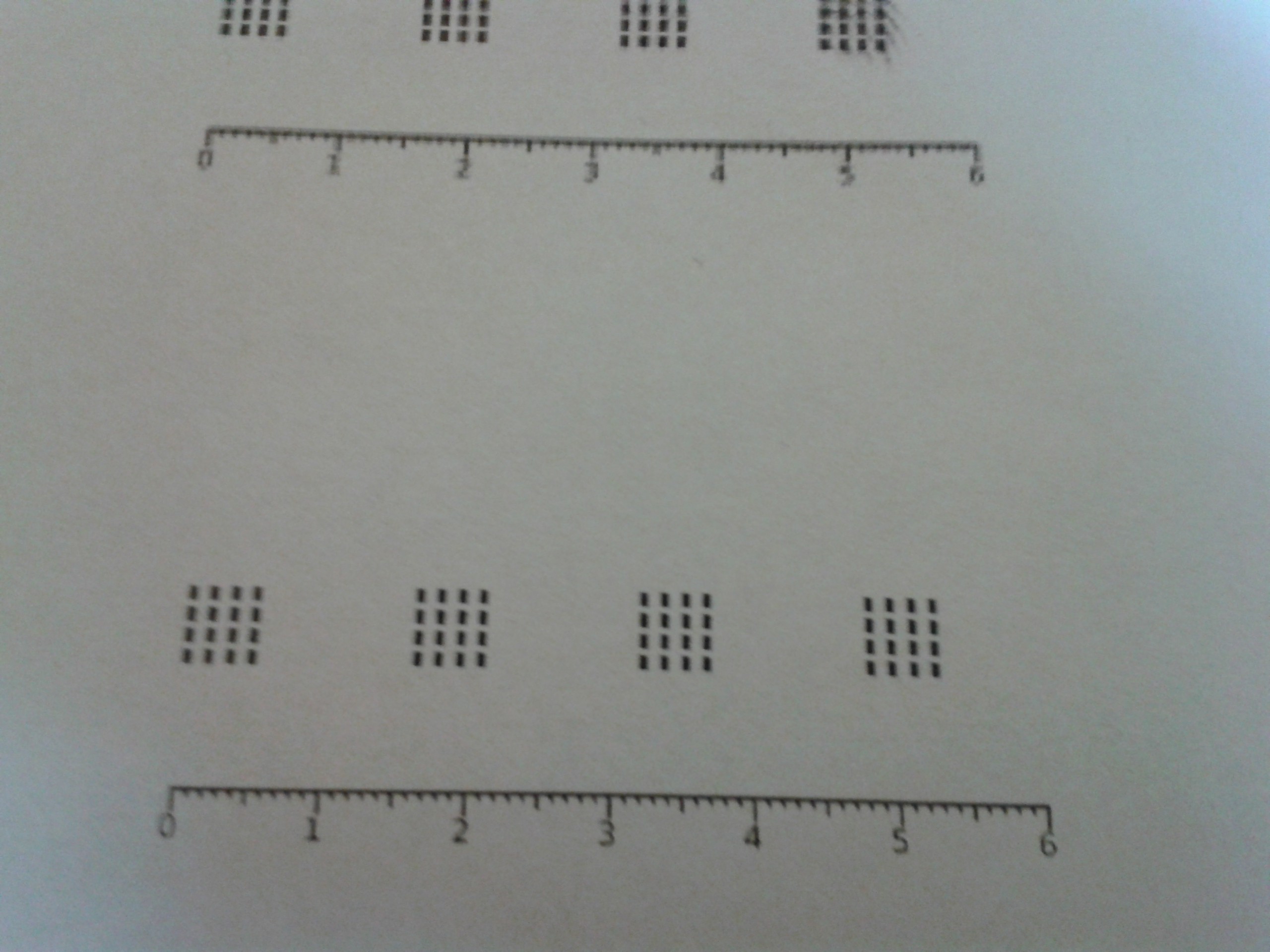
I decided to go back to the original idea of sticking them down in grids and hopping the wires like before. I printed a grid out so I could space them properly, and decided to give myself a bit of wiggle room.
5x5x5mm is plenty small enough for these things, besides, it was going to be 5mm tall anyway because of the wiring. These tolerances are getting a bit much in any case.
![]()
I tried a different glue. This is a Hi-Tack double sided tape. Its a layer of rubber, very thin and very sticky. It doesnt melt either, like the others. Must be based on Latex...
![]()
I bought better tools too, and modified them to handle components smaller than they were made for. A pair of nylon-tipped tweezers clipped with nail clippers and sanded with a fine emery board to pickup sub-mm devices without too much trouble.
Stll not small enough lol.
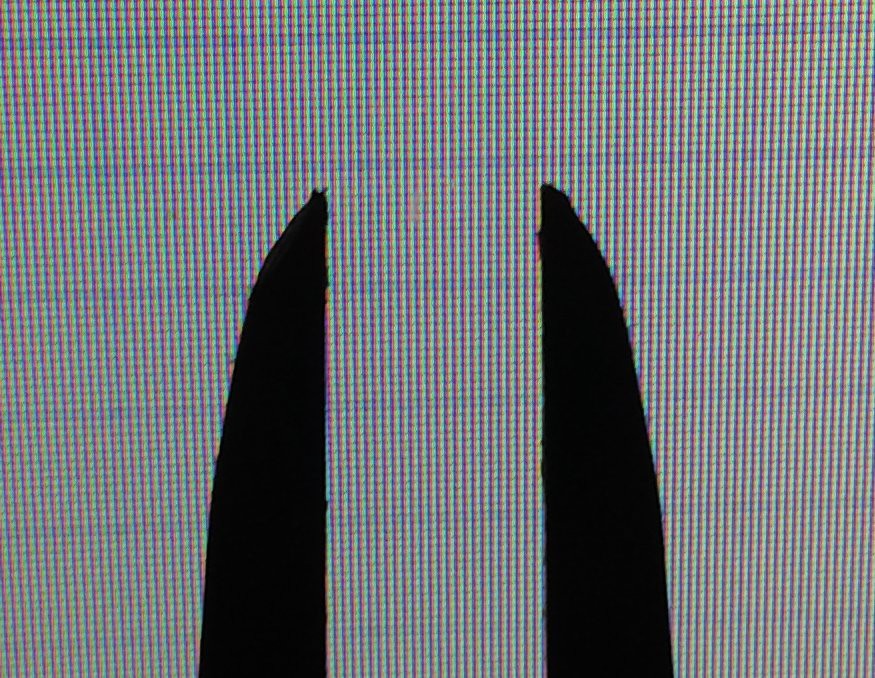
![]() Neither was the soldering iron. I tried several different wires on this in an attempt to do two things. One, I dont have a TCO, thats a plain 15W Antex with a needle bit. Way too hot and too big, the tip is the same size as the 0402 LED.
Neither was the soldering iron. I tried several different wires on this in an attempt to do two things. One, I dont have a TCO, thats a plain 15W Antex with a needle bit. Way too hot and too big, the tip is the same size as the 0402 LED.
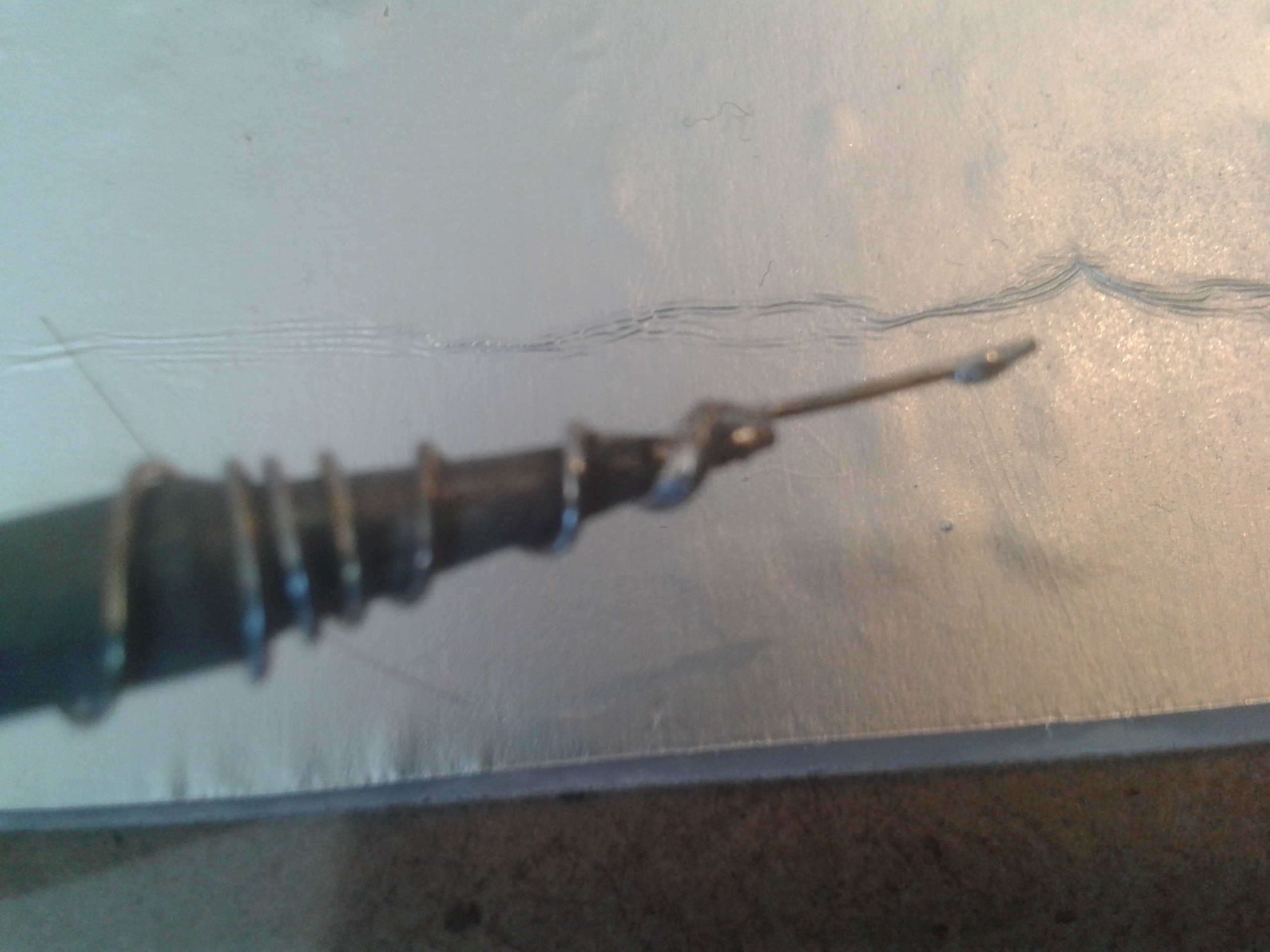
So, I added a coil of nickel wire to wick the heat and fit into the tiny spaces I was soldering. This worked ok, but like long-life soldering bits it wouldnt tin right.
.![]()
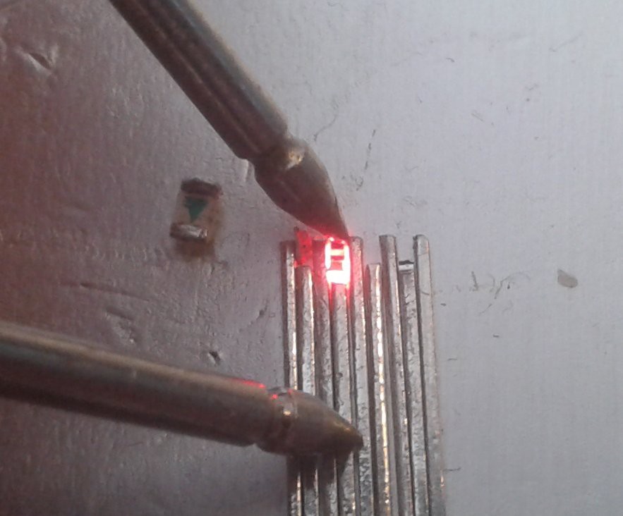
Give me a copper bit any day. They dont last, you have to keep filing them sharp but they wet properly and leave a beautiful finish on the solder beads. I made this one from 2.5mm mains cable and filed the end sharp. Once tinned, I can feed solder to the middle and it flows down into the joint the tip is touching.
Never touch the component with the solder or it will drown, and reflowing is a pain in the ass at this scale with more than three points to rest on. One of them is always going to wobble...
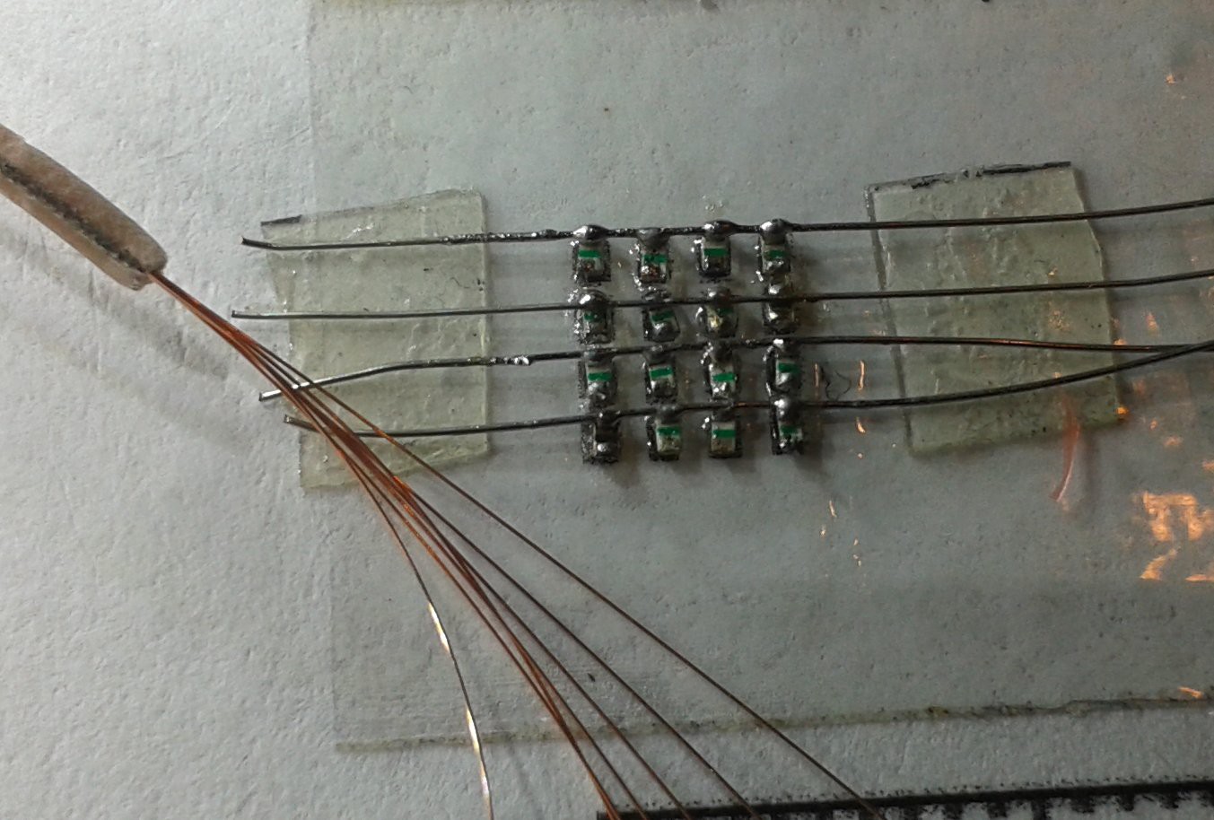
![]()
I found some even finer wire to solder the bridges with. I was going to use magnet wire this size, but I'm basically too lazy to scrape that stuff with a scalpel to solder it properly and it never tins right anyway.
Plus its so thin, chances are I'd nick it with the blade and it would break after I soldered it.
Do not try this at home, kids.
![]()
Things got a little out of hand here...
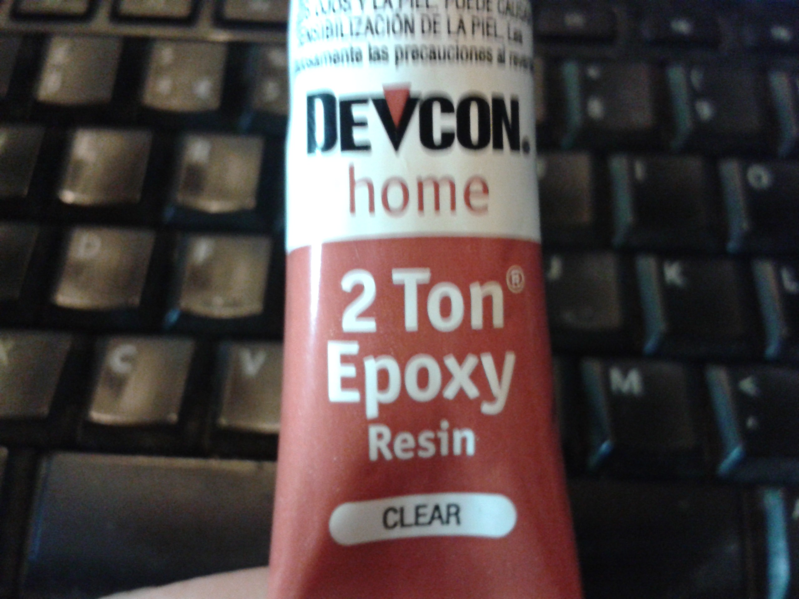
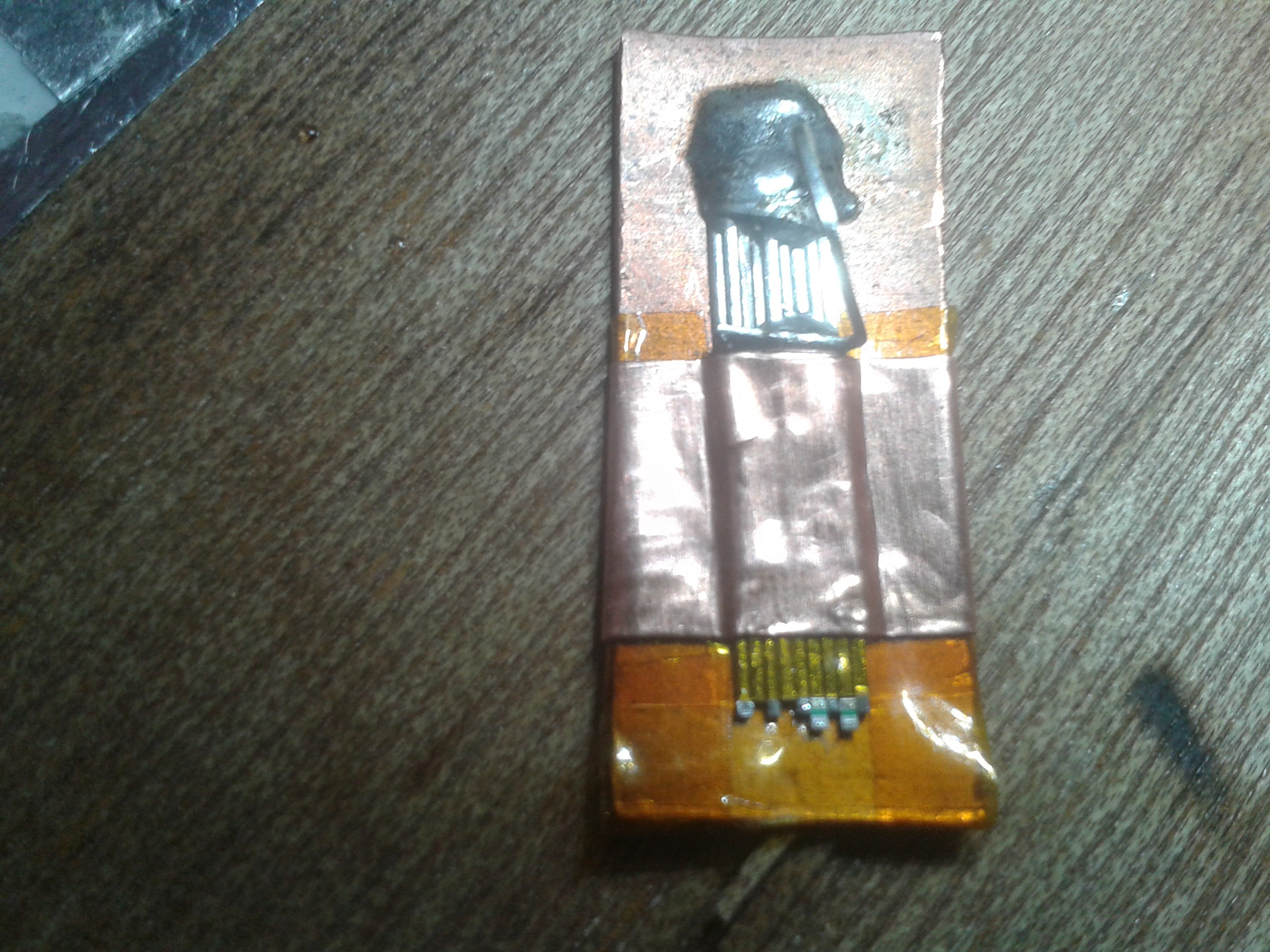
After a monumental struggle with the glue in the tape reacting with the nail varnish, which resulted in the discovery of Artificial Snot [patent pending] I gave up and made sure the LEDs stayed put. The spec sheet says 2,500lb shear / inch, that should do it.
![]()
It takes a while to cure, but after about 6 hours it gave up melting under the heat of the iron and held the LEDs in place firmly enough to work on them. Most epoxies melt, some burn, some run, some stink up the place but this one is well behaved. It even ignores nail varnish...
![]()
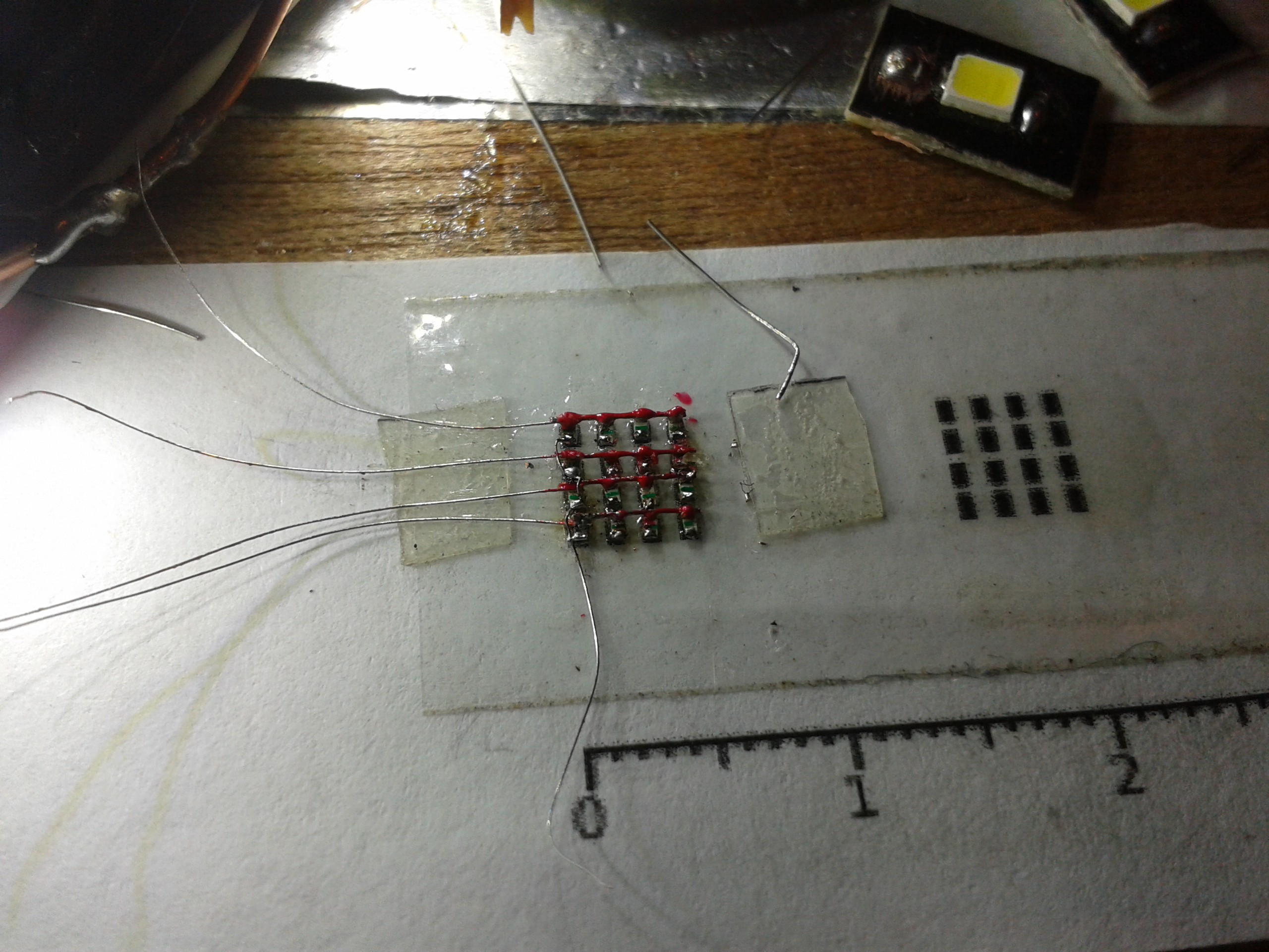
So, after a brainwave I realised I could put the lacquer on afterwards rather than scrape it off.
Cherry Bomb. Goes with everything, right ladies? XD
![]()
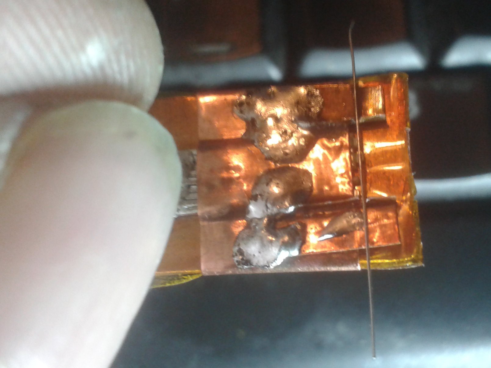
OK so this is as far as I've got this weekend. After trimming the main guide wires off by sawing through gently with a scalpel blade tight up against the LED I attempted to solder the finials to them, and with the epoxy holding them in place that works really well.
I'm now ready to complete this cube and start work on the next generation using 0201s.
Projections say this new 4^3 LED cube will weigh in at 0.25mm^3, breaking the world record in half twice running, after accidentally shaving a 6th off the original.
Currently there is no Guinness entry for a LED Cube, never mind the smallest, so I am applying. XD
I'm entering my original cube, and both the attempts separately... This means, as the application process takes 12 weeks to complete, that I could possibly also set a record for breaking my own record in half twice before the certificate comes out for the first one.
Can I get a MUAHAHAH? XD
-
MicroBugging
09/10/2018 at 09:05 • 0 commentsI'm using a large area of sticky tape, which holds these little devils so well you can also deconstruct and repair structures that would just fall apart. Careful modular construction prevents most of the problems anyway.
I spent quite a lot of time trying out various sticky surfaces. Double-sided tape is great as a working surface. It isnt too sticky, but it melts under the iron and tacks onto the LEDs making them sticky once soldered. The solder also tins it, which may or may not be useful.
I also tried Kapton, which was a dream compared to soldering on double-sided tape because it doesnt melt, and neither does the glue on it. However, the solder has a slight tendency to bead on the glue and leave edges on the wires but it doesnt actually tin it.
Last of all I tried metal tape. This is absolutely perfect, doesnt wrinkle or shrink even under abusive desoldering and the glue repels the solder in beads. I just layout a surface with double-sided tape and put a patch of ali tape inside it, glue upwards.
![]()
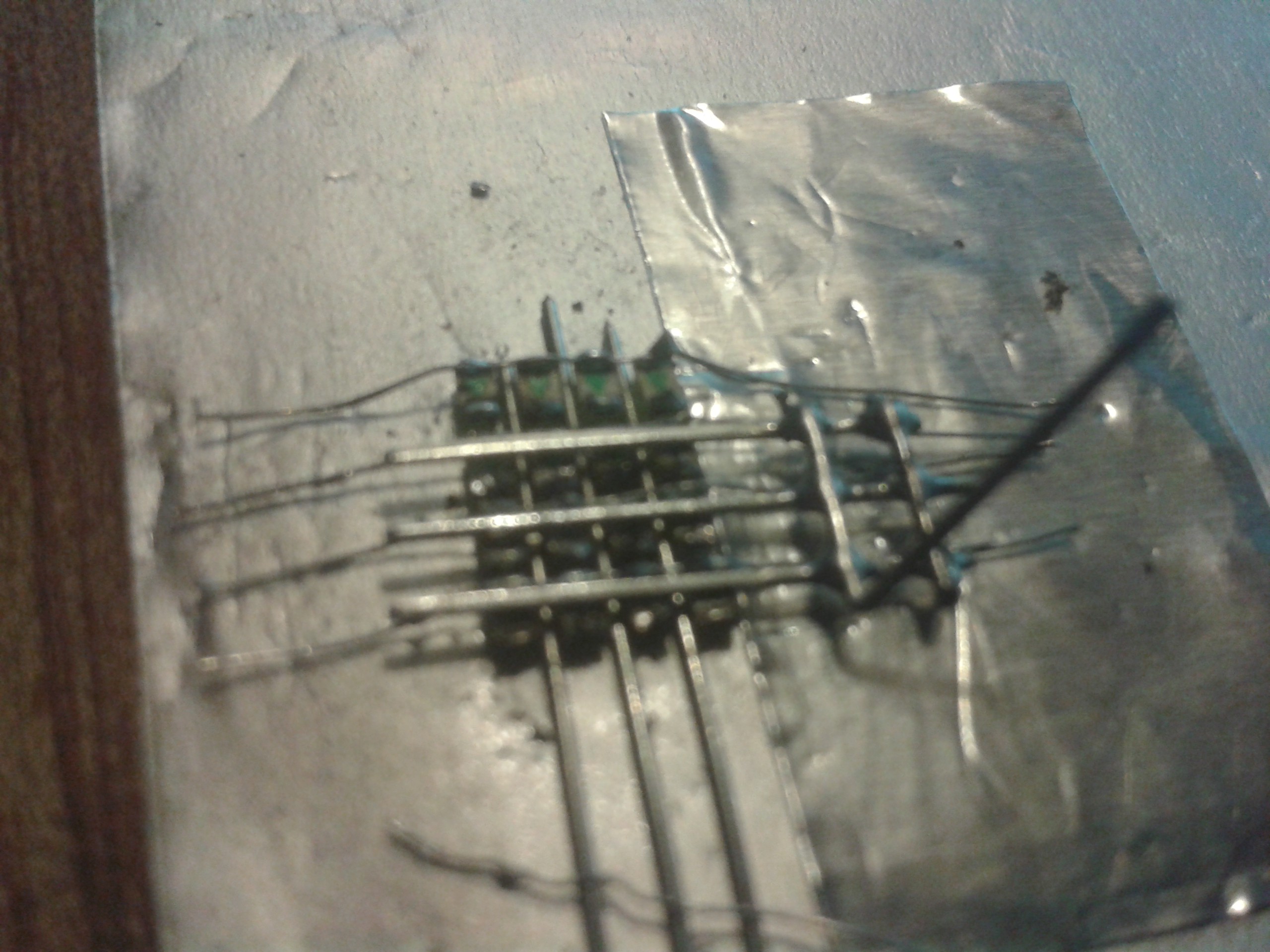
I took the cube apart so I could make it smaller after it occurred to me that the wire could also be used to line them up laterally.
![]()
So I made a guide, which worked really well. I just taped down the far ends and let the tape's glue hold it in place properly. Finally I added a patch of ali tape glue-down to rest my fingertips on while soldering under magnification. It doesnt stick that much, but it is enough to be annoying after a hundred times or more. ;-)
![]()
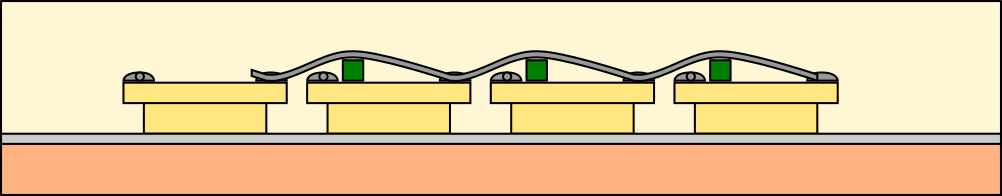
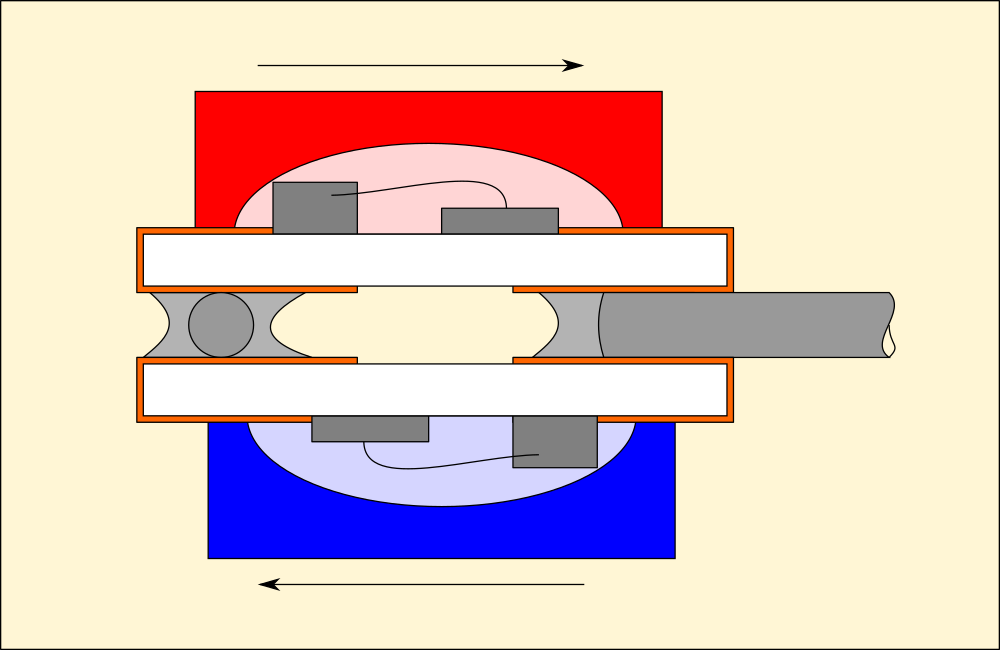
And finally, to form the wires properly I added a tiny jig the sits on the LEDs, lines them up correctly and provides a neat grid to run them over.
![]()
Jiggery Pokery
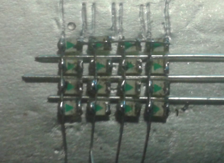
Simply bead and solder the top end, then press it into the grooves and remove the jig to solder the dips to the cathodes leaving clear loops over the anodes, which are all connected to the horizontals.
The above grid measures 9x8mm and is 2mm tall, making the completed device 9x8x8mm.
I am however running out of LEDs, they do not like being repeatedly heated and I have now got some dead ones, and one the contact stripped off. Any more problems from here on in, and I'll have dead pixels in the finished cube. However, I am witing on an order 0f 0402s to replicate this cube using double-sided LED banks so it is visible 360 degrees. Currently it is not visible from the back, as these LEDs are solid based.
The resulting room gained by using a device half the size will be lost by using two of them, and allowing a little more wiggle room for the wiring underneath, so the new version will be bicolour as well as 9x8x8mm.
![]()
The current cube is just Plexed, the LEDs go from anode to cathode in a grid. The new one will be Charlie-Plexed, which adds a new dimension to the code too. By switching the LEDs between red and blue using PWM, I can generate purple...


 Neither was the soldering iron. I tried several different wires on this in an attempt to do two things. One, I dont have a TCO, thats a plain 15W Antex with a needle bit. Way too hot and too big, the tip is the same size as the 0402 LED.