-
3. Accessing SD card using SPI on LPC2148
11/26/2018 at 13:05 • 0 commentsSD card data access can be done in SD mode as well as SPI mode. The latter is more frequently used for embedded systems. SD involves block read/write operations, a single byte can never be read or written. Typical block size is 512 bytes.
The SPI mode is compliant with the Serial Peripheral Interface (SPI) specification. Its bus
architecture includes the following signals:
1. CS: Host to card Chip Select signal
2. CLK: Host to card clock signal
3. MOSI: (Master Out Slave In) Host to card single bit data signal
4. MISO: (Master In Slave Out) Card to host single bit data signalIn order to configure SPI interface on the LPC2148 SSP port, the design consideration
includes,
• GPIO setting. The SPI pins, CLK, CS, MOSI, MISO need to be configured through
pin select and GPIO registers, PINSEL1, IODIR0, and IOSET0, before configuring
the SPI interface.
• SPI clock pre-scale and clock rate. Based on the APB clock (PCLK) setting in APB
Divider Control register (APBDIV), the clock pre-scale can be set through SSP Clock
pre-scale Register (SSPCPSR), and the clock rate can be controlled in the SSP
Control 0 Register (SSPCR0). The SPI clock rate in the sample test program is set to
4 MHz.
• SPI frame format and data size. The SPI format and data size can be configured
through setting the proper clock polarity bit (CPOL) and clock phase bit (CPHA) and
data size field (DSS) in the SSP control registers (SSPCR0). The data size is set to
8 bits/frame, and both CPOL and CPHA bits are set to zero.
• SPI enable/disable. The SSP port should be disabled before the GPIO pin setting,
clock pre-scale setting, frame format configuration, and enabled after all the
configuration is done to ensure a clear start.The SPI related APIs in the attached sample program include:
• void SPI_Init ( void );
Initializing SPI interface through configuring GPIO, VPBDIV, SSP port registers.
• void SPI_Send ( unsigned char * data_pointer, unsigned int data_length );
Sending a block of data based on the data pointer and the length of the data block.
• void SPI_Receive ( unsigned char *data_pointer, unsigned int data_length );Receiving a block of data based on the data pointer and the length of the data block.
• unsigned char SPI_ReceiveByte( void );
Receiving one byte of data, the return value of the API is the received data. This API
is primarily used to obtain the command response at different phases.Basic SD/MMC commands
A command frame is first sent to which the SD card responds on the basis of the command number.
The standard commands are listed below:
CMD0 GO_IDLE_STATE, reset the card to idle state
CMD1 SEND_OP_COND, ask the card in idle state to send their operation
conditions contents in the response on the MISO line. Any negative response
indicates the media card cannot be initialized correctly.
CMD16 SET_BLOCKLEN, set the block length (in bytes) for all the following block
commands, both read and write. In the sample program, the data length is set to
512 bytes.CMD17 READ_SINGLE_BLOCK, read a block of data that its size is determined by
the SET_BLOCKLEN command.
CMD24 WRITE_BLOCK, write a block of data that its size is determined by the
SET_BLOCKLEN command. -
2. LPC2148 USB Bootloader
11/26/2018 at 10:03 • 0 commentsThe two main references that helped tremendously in implementing USB bootloader were
[1] SparkFun LPC2148 Bootloader Tutorial https://www.sparkfun.com/tutorials/94
[2] AN10711 USB secondary ISP bootloader: Application Note, Rev. 02, 15 July 2008.
While both references assume different FAT size, different programs and code, a combination of files drawn from both sources proved to be fruitful for this project.
The LPC2148 USB bootloader performs three steps:
1. The bootloader checks to see if a USB cable has been plugged in. If the LPC2148 detects the
presence of a USB cable then it initiates a USB Mass Storage system. This will cause the
target board to appear on any computer platform as a removable flash drive. The user can
then seamlessly transfer files to the flash drive. In the background, the LPC2148 moves the
user’s files onto the SD card using the FAT16 file system.2. The next thing the bootloader does is look for a firmware file (a file named FW.SFE). This
file contains the desired operating firmware (in a binary file format) for the LPC2148 microprocessor. If the bootloader finds this file on the FAT16 system then it programs the
contents of this file to the flash memory of the LPC2148. In this way, the bootloader acts as
a "programmer" for the LPC2148; and we can upgrade the firmware on the LPC2148 simply
by loading a new file onto the micro SD card.3. After performing the first two checks, the bootloader calls the main firmware. The main code
should not even know that the bootloader was used and will run normally.The USB device class used is MSCD (Mass Storage Class Device). The MSCD presents easy
integration with PC’s operating systems. This class allows the embedded system’s flash memory
space be represented as a folder in Windows/Linux, and the user can update the flash with the
binary image using drag and drop (eg, using Windows Explorer).To make the LPC214x appear like a folder (or disk drive), we need a FAT (File Allocation table).
The LPC2000 on chip Code Flash will appear as one single entity (file name: firmware.bin).
In order to run this program, the WinARM programming environment is used. The version used
is WinARM 20060606. It’s an open source IDE, similar to Keil. Given that it was a text editor,
programmer and compiler before more advanced IDEs like Keil came along, WinARM was later
found to be incompatible with Windows 10 OS. All MakeFiles to generate main.hex were executed
on a laptop running Windows7.LPC2148 USB Bootloader Source Code (from [1]) contains a whole bunch of source code, including
two subdirectories: LCPUSB and System, along with the startup assembly code (crt.S) and the
linker file (lpc2138.cmd).A combination of programs/libraries from the USBMem demo of AN10711 and the SparkFun tutorial (drawn from Bertik Sikken), successfully works. Figures below show the LPC
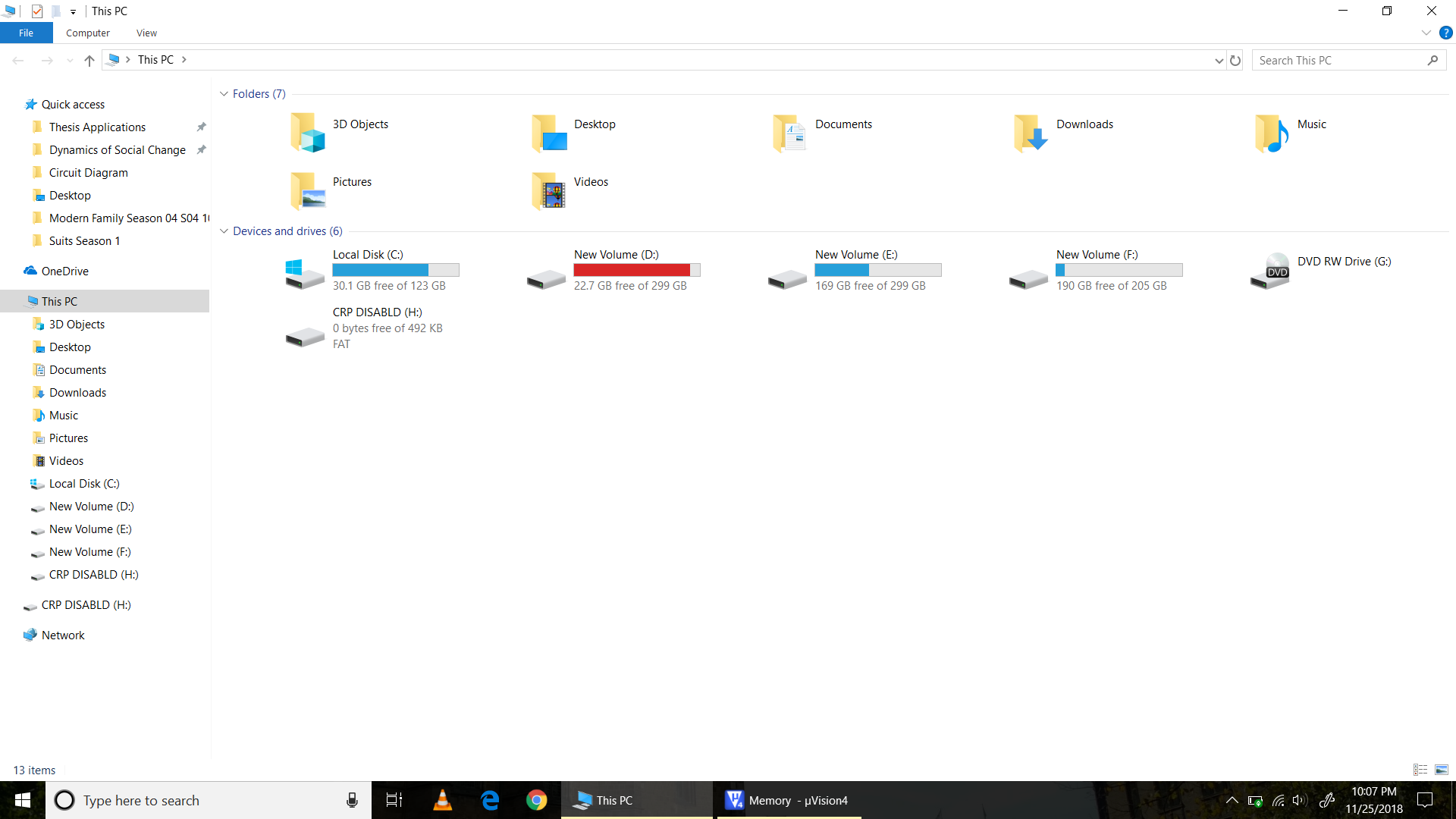
recognized as a Mass Storage device in an Explorer windowfirmware.bin in LPC2148 Flash recognized as mass storage device CRP DISABLD USB Mass Storage -
1. USBMem
11/26/2018 at 07:17 • 0 commentsThe first attempt made was to reproduce a demo USB-based mass storage program for the Keil
MCB2140 Board using the Philips LPC2148 Microcontroller. Given that UM10139 was being used
and not the MCB2140 board, only the startup file needed to be changed and the main program
written for the MCB board would still be compatible with that for UM10139.OBJECTIVE
The USB Memory should be automatically recognized by the host PC running Windows which will load a generic Mass Storage driver, such that the microcontroller board acts as a USB Mass Storage Device (MSD) and the PC acts as the USB Host. The on-chip RAM is to function as MSD.
DETAILS
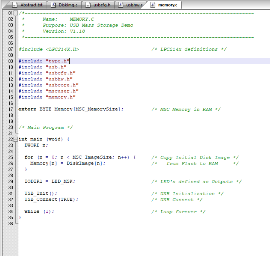
memory.c is the main file which starts the Mass Storage Device. It uses the following files:
• Startup.s: CPU startup file for the NXP LPC2148 device.
• usbhw.c: USB hardware layer for NXP LPC2148.
• usbcore.c: USB core module that implements the basic USB communication layer.
• usbdesc.c: USB device description.
• usbuser.c: HID custom module.
• mscuser.c: Mass Storage Class implementation module.
The figure below shows memory.c in the Keil window.CONCLUSION
Due to issues of compatibility with the UM10139 board, the code did not successfully compile.
Attention was then shifted to the LPC2148 USB Bootloader
USB MicroSD card reader
Reads the data from MicroSD card interfaced to LPC2148 and sends via USB.


