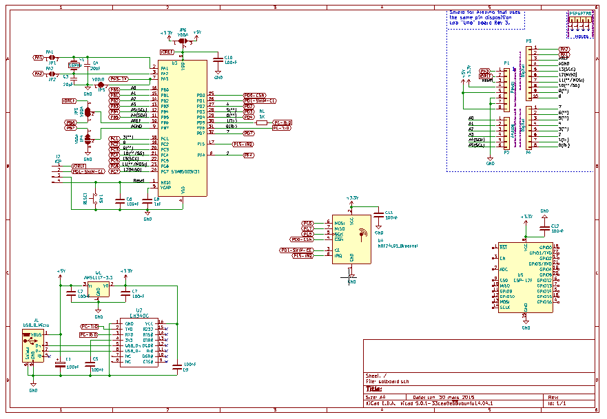
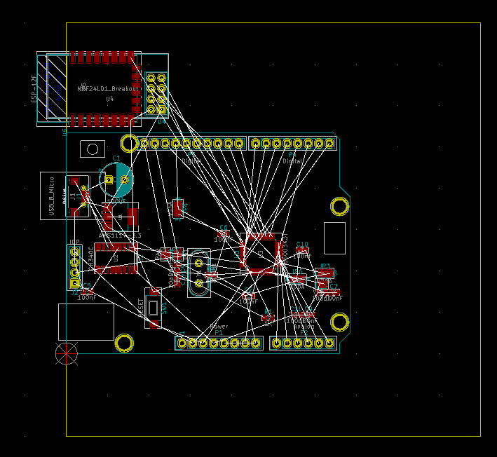
I started designing the core around STM8Sx003K3T6 (or alternatively STM8S105KxT6), and since I'd like to have a board for all kinds of "remote stuff" I decided to add an Arduino style connector, an ESP-07S/ESP12F socket, a CH340 USB/serial converter, and other goodies.
I decided to assign GPIOs to the Arduino header so that using cheap Arduino Shields is possible (Arduino Playground's Shield Pin Usage table was very helpful). Of course, one-to-one GPIO grouping isn't possible but a bit of glue code can fix that.

While using Arduino Shield shall be possible, the SolBoard should make best use of the 10x10cm² panel size that budget PCB houses "hand out" to the masses. I hope to find the right mixture of features and pragmatism so that my solar controller board can also be used as a prototype board or for other logging or control use cases.
The general layout of the board is this:
- East:
- RF, USB and control inputs,
- West::
- SSR, power supply and heavy-duty connectors
- North and South:
- 5mm spacing for a 100mm wide "aluminum profile case",
- maybe a small breadboard area

There are now some things to decide:
- Which power supply module to use?
- How to design surge and overload protection?
- One or two SSRs?
- How to do milling for insulation?
- Which type of ESP8266 and nRF24L01 module (e.g. external or PCB antenna)
I would be happy to receive some advice from the community!
 Thomas
Discussions
Become a Hackaday.io Member
Create an account to leave a comment. Already have an account? Log In.