-
Second Rev of Boards with new Paste Mask is Back.
11/10/2018 at 23:27 • 0 commentsI made some minor tweaks to the digit PCBs, mostly adding some pull up resistors to logic inputs. The main thing that I did was reduce the paste mask openings on the QFN packaged 74HC595 parts. The thermal pad mask was reduced to allow a paste spot 60% of the size of the pad and on the individual pads (0.012" x 0.031"), I set the paste mask expansion value to -0.002". When I mounted the parts, the amount of paste on the thermal pad seemed about right. The part set right down on the board, as nice as you could ask for. The individual pads needed more solder paste. After the -0.002" paste mask expansion, the pin pads got 0.008" x 0.027" openings. Comparing the area of the pad to the area of the shrunk paste mask, there was still about 58% of the pad exposed. The paste I used seems kind of stiff, it may be that I just did not apply it correctly, but I think that it will be worth getting another mask with -0.001 paste mask expansion. A project for another day.
The 4 digit carrier board that I build now has all 4 digits in place and driven by the test software. There is something very pleasing about the "rounded" corners that this display type affords.
-
4 Digit Carrier Boards are Back
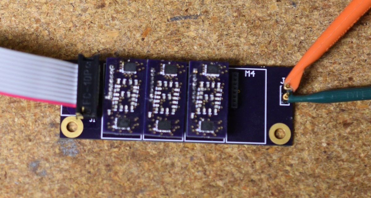
10/28/2018 at 00:17 • 0 commentsThe carrier boards that allow up to 4 digits to be plugged in and run in a single SPI chain have come back from OSHPark. They are simple boards and they work fine. I built up the last two of the bare digit boards to test the carriers. The picture below shows the carrier board with 3 digits populated.
![]()
I wrote a quick and dirty test program to drive the board using an Aardvark USB to SPI adapter, and it looks good to the human eye. Unfortunately, photos with the digits lit turn into a big red blob. I need to try a contrast filter for that.
Building up the other two digit boards was semi-painful. The 74HC595 shift register chips I used are in QFN packages with a thermal pad in the middle. Due to the small size of the LEDs (0402), I got a solder paste stencil to make it easier to build. The thermal pads had WAY too much solder paste on them and the parts floated up when I reflowed them. TI has an app note (thanks Jarrett) on making footprints for QFN packages that suggested putting a grid pattern on the thermal pad with about 60% exposed for paste. That is going to take some effort to implement, so I just made a paste mask pad about 60% of the pad size. I will see how that works out on the next board rev that was submitted today.
My curiosity on whether displays could be built and how they would look is pretty much satisfied at this point. Now I want to see what is required to solve the solder paste mask issue.
-
SPI Interfaced Digit Boards are Back
10/13/2018 at 23:14 • 0 commentsBare boards for the SPI interfaced version of the displays arrived from OSHPark. Using the solder paste stencil for the top side of the board, assembly went pretty fast. I opted for the stencil on the top side because it has the LEDs and QFN packaged 74HC595 chips. The back side of the board was done by hand, and was a little painful because there are no component designators and the parts are all 0402 packages. Anyway the board went together last night, and it occurred to me that the fastest way to hack a test driver together would be to drive it from my PC using an Aardvark (Total Phase Systems) for the SPI interface. The API for the Aardvark supports SPI, I2C, or GPIO. It can be a little fiddly to get the signal polarities configured correctly, but it is easy to change the configuration. The 1.27mm header connectors were too small to get clips onto directly, so I soldered 30 gauge Wire Wrap wire pigtails on for testing.
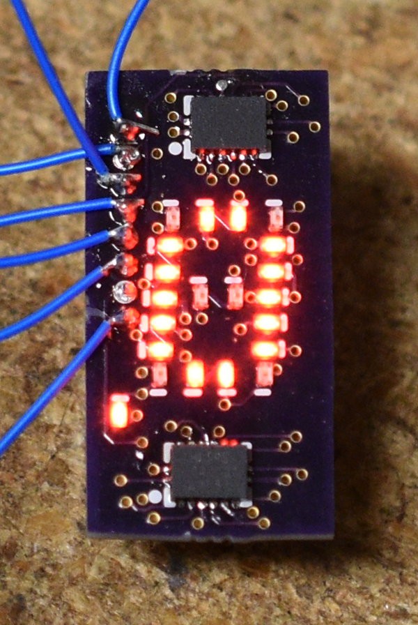
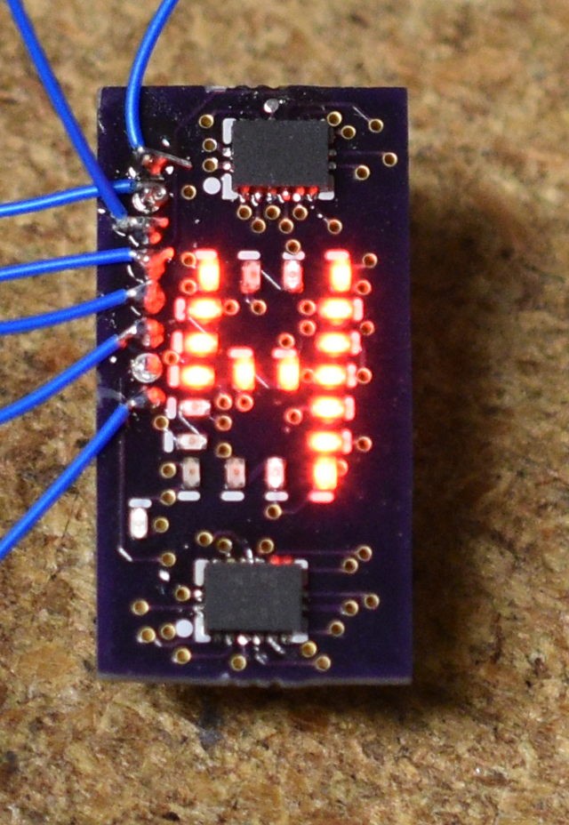
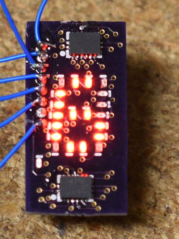
Here are a few digits:
![Board with 0 digit lit. Board with 0 digit lit.]()
Board with 0 digit lit. ![Board with 4 digit lit. Board with 4 digit lit.]()
Board with 4 digit lit. ![Board with 6 digit lit. Board with 6 digit lit.]()
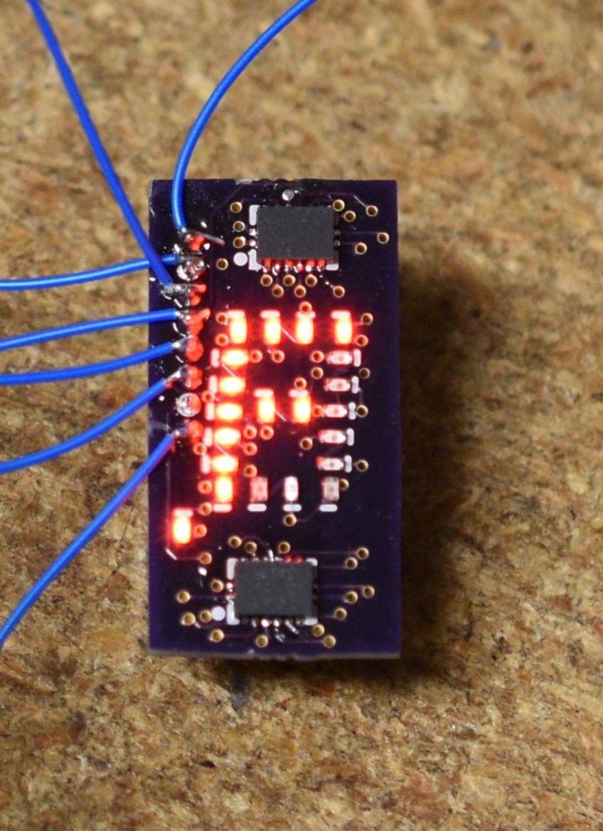
Board with 6 digit lit. ![Board with F digit and Decimal Point Lit. Board with F digit and Decimal Point Lit.]()
Board with F digit and Decimal Point Lit. One thing that I discovered while testing the driver is that the Master Reset signal on the 74HC595 only resets the shift register and not the output latches, rendering it useless in this application. The Output enable will still be useful for a blanking input though.
The next step will be to lay out a carrier board to hold several digits and make it easier to connect for testing. It also needs a filter to improve the contrast some to make it easier to read.
-
Built up a Test Driver
09/30/2018 at 22:11 • 0 commentsI was digging through a box of parts from a previous project, and I found a bag of 2N3904 NPN transistors, perfect for building up a 1 off test driver for my first iteration of display boards.
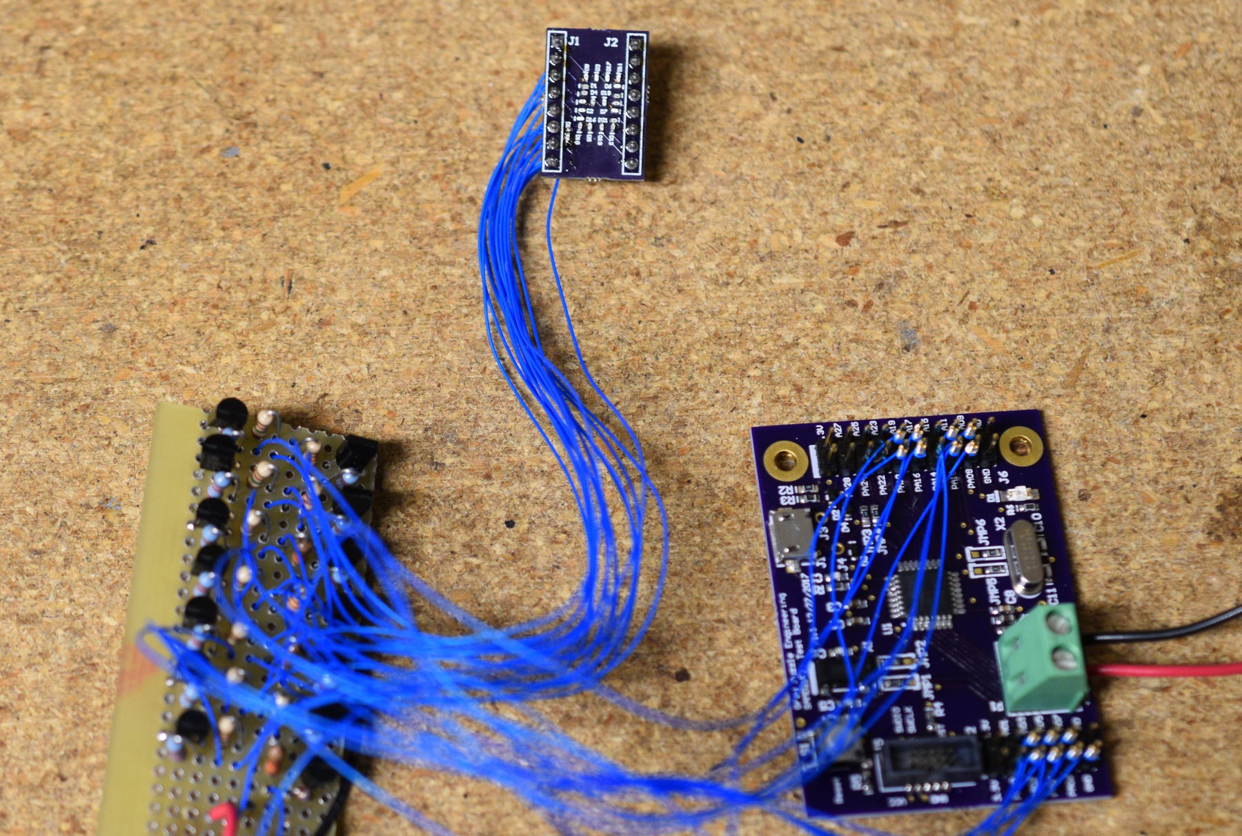
The perfboard on the left side is the NPN driver board (14 NPNs wires as common emitter), the board on the right is one of my ATSAMD21E18 protoboards and the board in the middle is the display. After some futzing around to get bit I/O assignments correct and clean up my character generator table, the display looks pretty good. The multitude of wires makes me glad that the PCB for the SPI interfaced version is out being fabricated. Seven of the LEDs are wired as single LEDs on that circuit and the others have 2 LEDs in series on a single circuit. The single LED circuits get a 3.3K current limiting resistor and the double LED circuits get a 1.8K current limiting resistor. The LEDs are running in a 5V circuit. The brightness between the single and double circuits matches pretty well with this approach. The SPI interfaces version implements the same approach, just all on one board.
It's funny, I have gone away from perfboard projects in the last few years. Most of what I build is surface mount and when I mess up a connection or two on the pcb, it is easier to put in a wire or two than to build the whole thing. This driver board was sort of an exception because it was all through hole parts, I don't think I will ever need more than this one, and I didn't want to wait the turn around time on the PCB fabrication.
Anyway, the display looks good in operation.
-
A Board With Drivers on it
09/29/2018 at 00:23 • 0 commentsI sat down last weekend to see what I could put together to drive the LEDs on this display board. About half the segments have 2 LEDs in series, so it needs 5V power (with current limiting resistors). Neither of the boards that i wanted to use have 5V tolerant I/O. With Radio Shack gone, I couldn't run down and get one of the bags of 50 2N3904 NPN transistors.
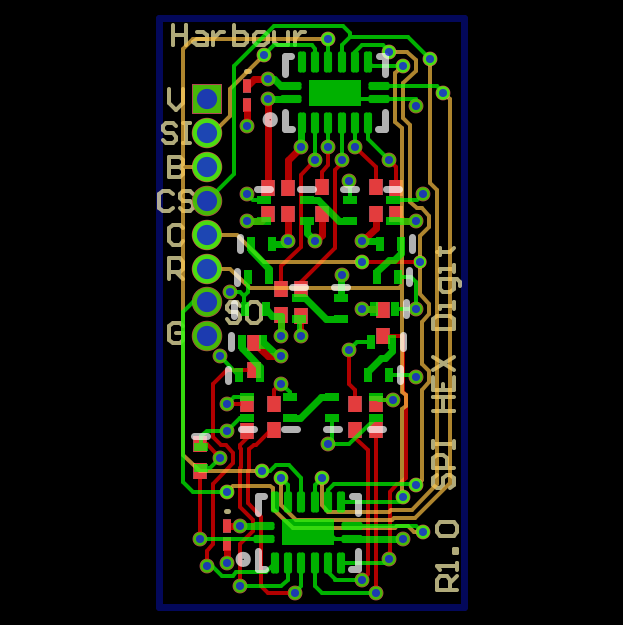
Looking around on Mouser's web site, they have the 74HC595 shift registers in little leadless packages. With a little messing with, I got two of those parts, along with 14 current limiting resistors to fit on a PCB. Swapping the two 0.1" connectors for one 0.050" connector, I was able to narrow the PCB by about 0.150" as well.
![]()
Green: Top side copper Red: Bottom side copper Yellow: Mid Layer 1 and there is a ground plane that is switched off in this view for visibility. The board is about 0.450" x 0.780"
I sent the boards out to OSHPark this week. With the 0402 LEDs and two of the QFN packages on the top surface of the board, I went ahead and ordered a stencil for solder paste. These things are not going to be a lot of fun to build. Next rev, I will fix the silkscreen on the bottom layer (it's reversed) and whatever electrical issues I find after building one.
I ordered the parts to populate these boards, and while I was at it I ordered some 74HC125 drivers to play with the existing boards.
Homebuilt LED Displays
This is an attempt to re-create a long obsolete Hex LED display.
 Bharbour