I have everything but the keys and diodes are soldered on. The board should be able to run the ROM code. Except it doesn't. I burned the ROM and it doesn't seem to be running the code. It does appear to be running SOME code, but not the correct code. I'm wondering if I perhaps burned the ROM incorrectly. I need more time to investigate, but it does not execute the first few instructions which can easily be probed on the board. I can read the code back off the ROM, so I know it's burned. I'll need to decode each instruction to verify it's correct, but more time is needed which I have very little of lately. I need to retire so I can have more fun with hobbies. Unfortunately I have at least another 20 years to go...
Discussions
Become a Hackaday.io Member
Create an account to leave a comment. Already have an account? Log In.
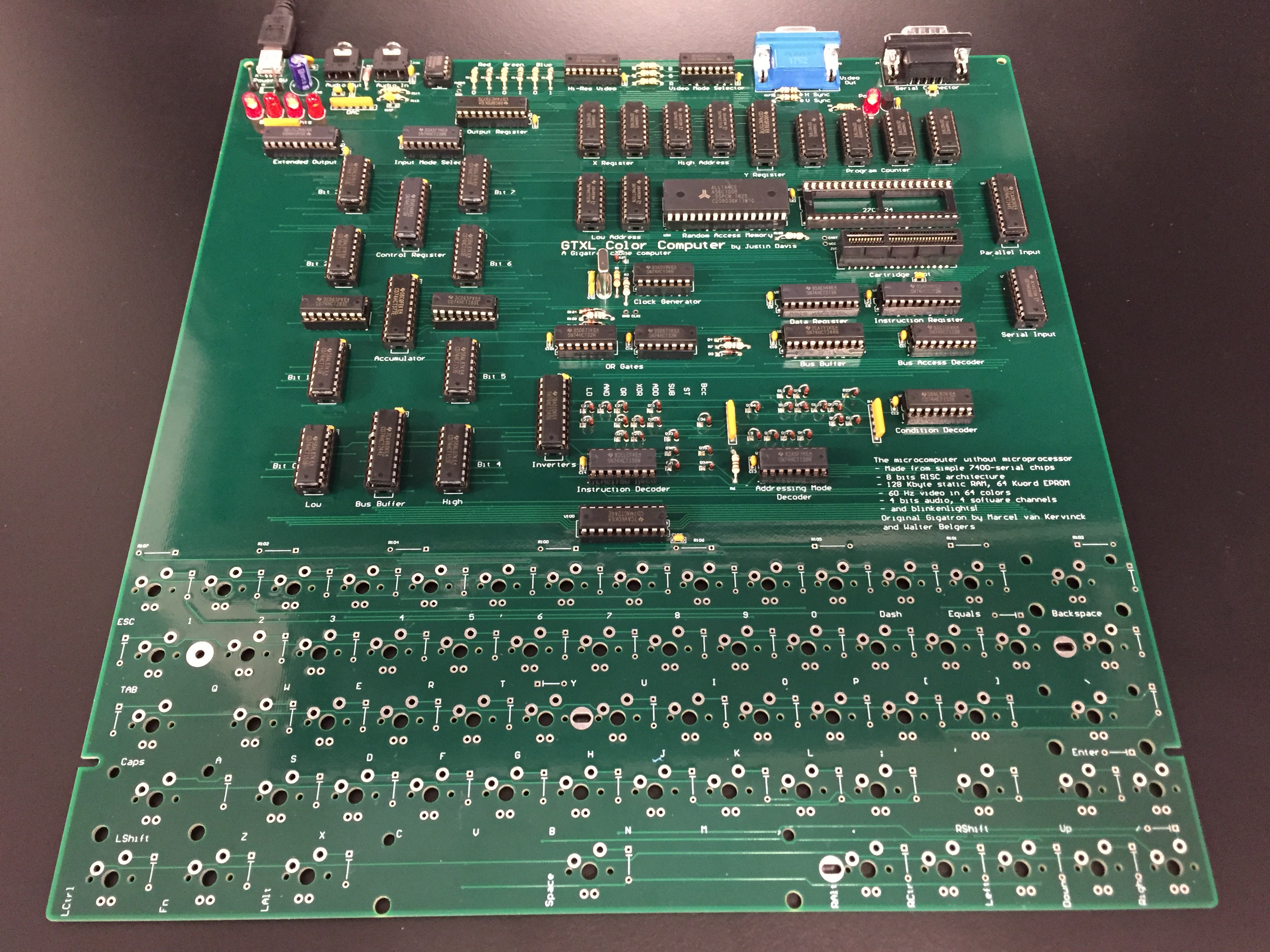
On a normal Gigatron kit all chips must be aligned the same direction: Notch to the left for the horizontal ones, and notch up for the vertical ones. The output register looks suspect here. Some others as well, but they're specific for the GTXL. Easiest troubleshooting is by probing the program counter outputs.
Are you sure? yes | no
If you look at the silkscreen under the output register, the chip does follow the pin 1 notch. I suspect he might have rotated them for ease of layout? Either that or the silkscreen layer is wrong. He did mention previously having to reproduce some of the symbols in Altium, so it is a plausible source of error. He already talked about a mistake with the diodes, so that's why I was suspicious of D3/D4.
Are you sure? yes | no
Any chance you swapped bytes when programming the ROM?
Are you sure? yes | no
Hard to tell without schematic/layout files, but are you sure D3/D4 (as well as the new D163/D164) are installed in the right orientation? See https://unicorn.drogon.net/IMG_20180422_122932.jpg and https://gigatron.io/wp-content/uploads/2018/06/cropped-kistje-productie-1000.jpg and ~2:54:30 https://www.youtube.com/watch?v=wECZoUNd2GY
Are you sure? yes | no