-
Cart & Programmer PCBs
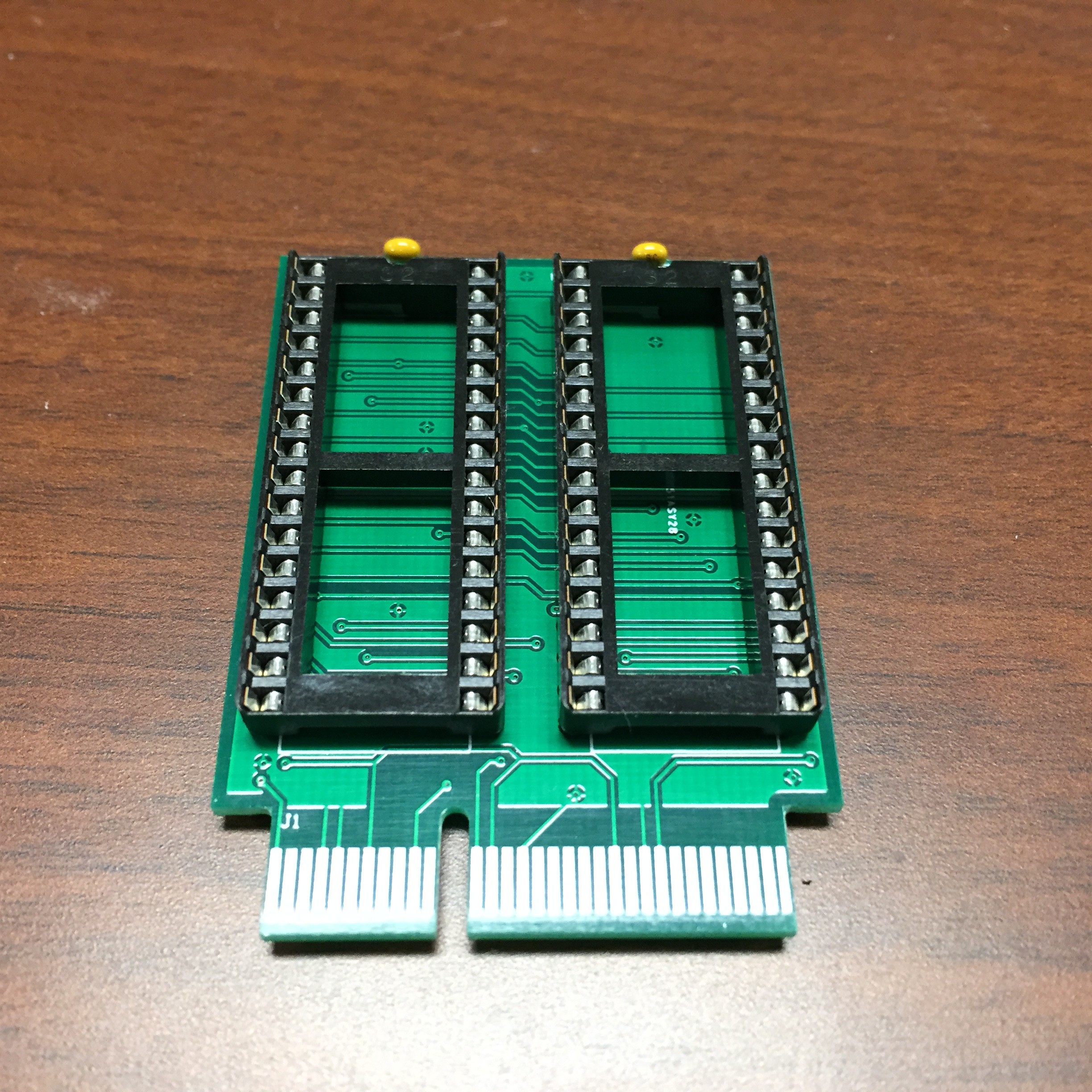
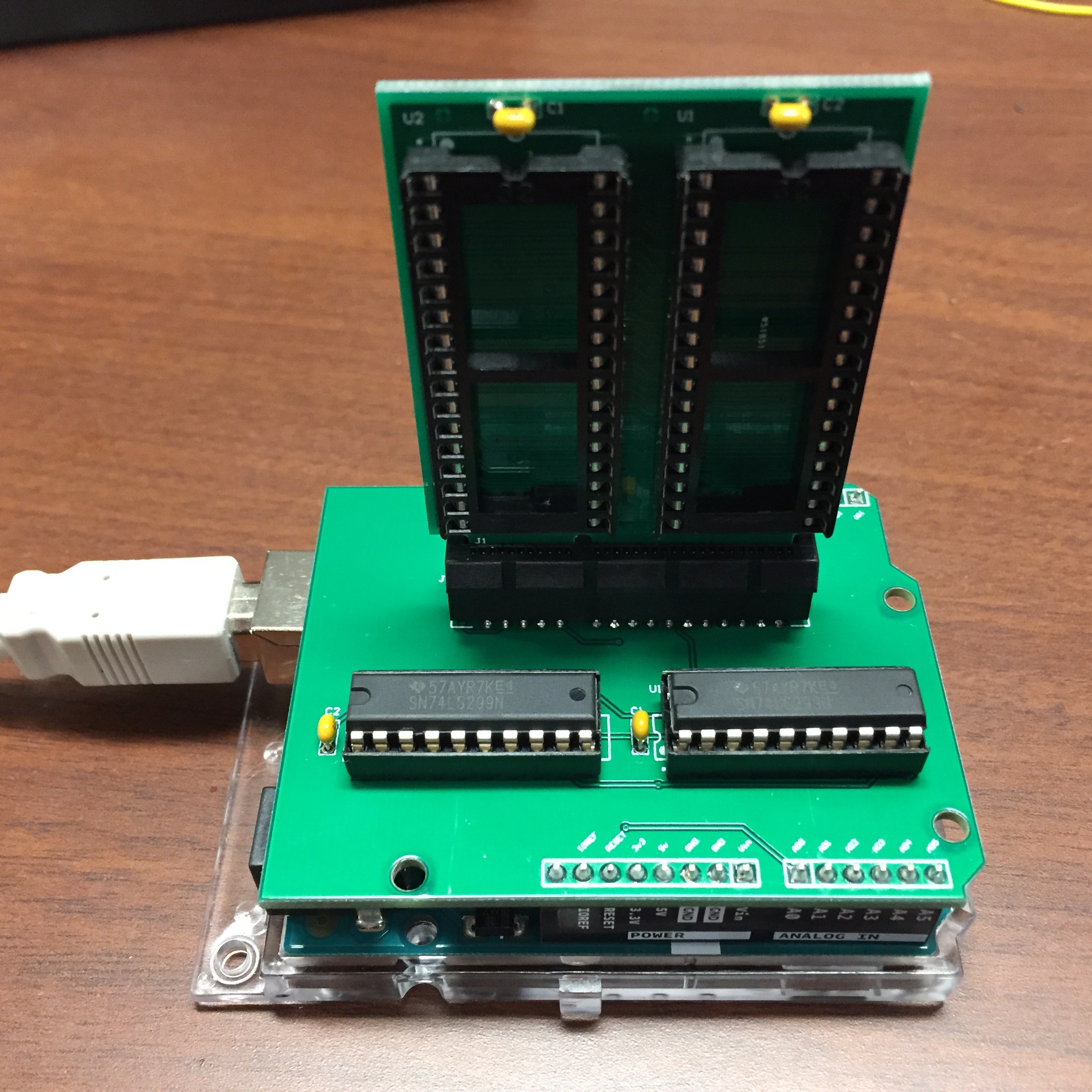
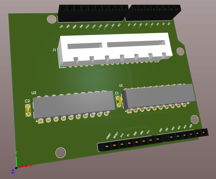
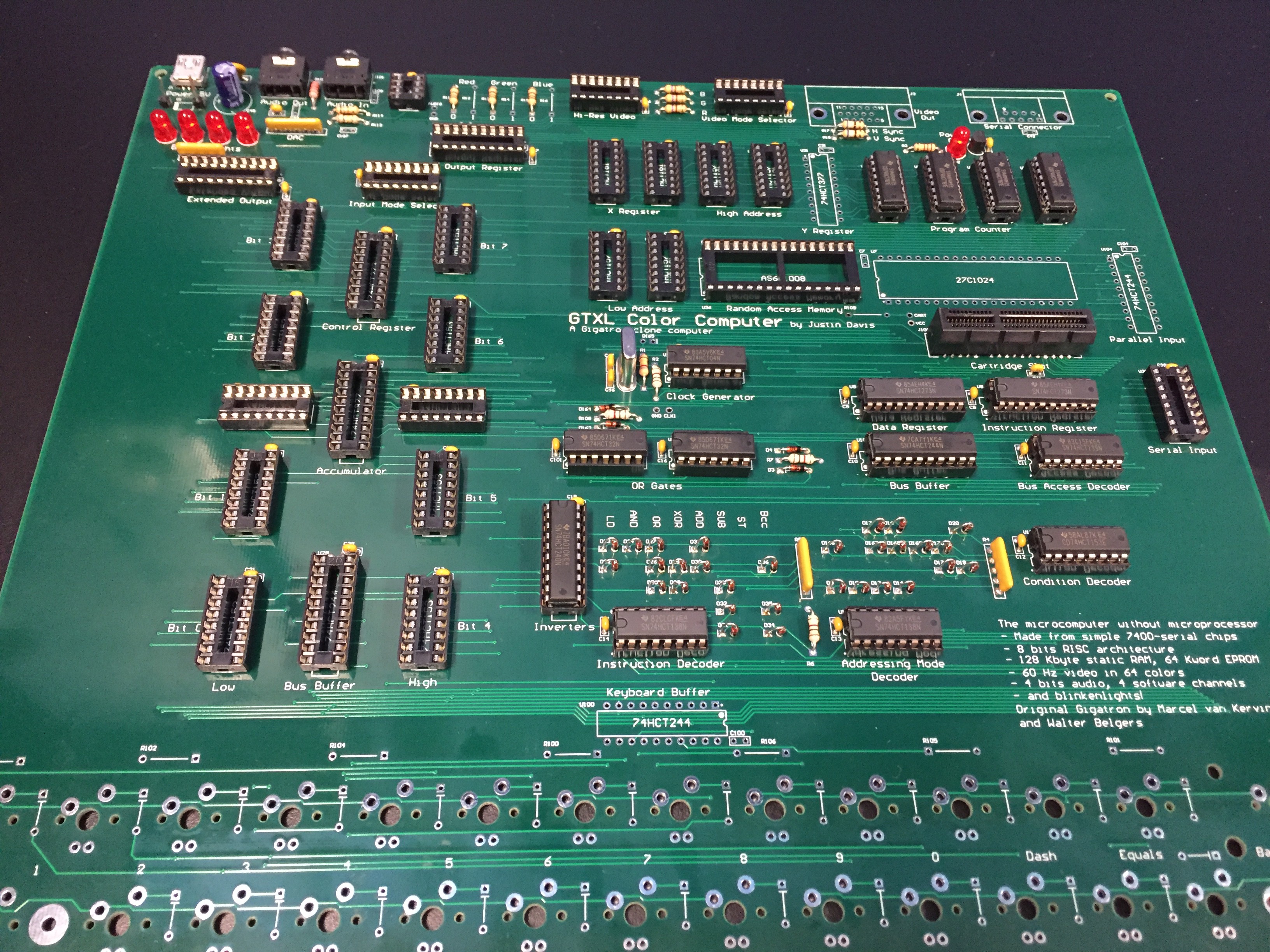
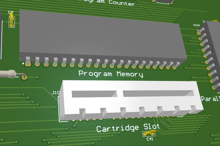
02/21/2019 at 18:47 • 0 commentsI received the PCBs for the cartridge and the programmer. I've built them up, but haven't started programming. I'm still working on the Arduino code to load the software. I used two 8-bit shift registers to hold the address, and then I directly interface the data bus for each chip. I can control the output and write enables independently for each chip, so I can combine the two data buses. This lets me read and write the whole address space for each chip. I have to admit the cartridges are pretty sweet and a nice size. Maybe I'll put together a 3D printed case for it. Unfortunately I didn't think of putting in any mounting holes for that.
![]()
![]()
-
Flash cart and programmer
02/14/2019 at 19:17 • 1 commentI finally have a small amount of time to revisit the Gigatron XL. I left it off at having problems with my PROM executing the correct code. I first need to verify the correct commands are coming out of the PROM. I know the code is in the PROM, but I'm concerned the bytes are swapped. So I need to do some debug.
Second problem is the PROM are one-time-programmable, and I don't want to go through a ton of PROM chips. So I went ahead and made the Flash cartridge board which is re-writeable. I then needed to make a programmer for that board, so I made another board which is an Arduino shield only for the purpose of reading and writing my cartridges. They are now both on order at https://www.pcbway.com/. And I don't know if it's been a long time since I ordered a simple 2-layer board, but yo are they inexpensive. On the order of $2 per board. These prototypes would have cost me more like $100-200 per board like 6-7 years ago. It's crazy how much the prices of bare PCBs have fallen. The biggest cost for the Steves in the Apple 1 development was the cost of the PCBs. Jobs sold his car to afford them. And I'll have them in about a week, so I can continue development work soon.
Next up is writing a small piece of my own machine language code just to verify it is coming out of the PROM/Flash correctly.
-
All but keyboard soldered
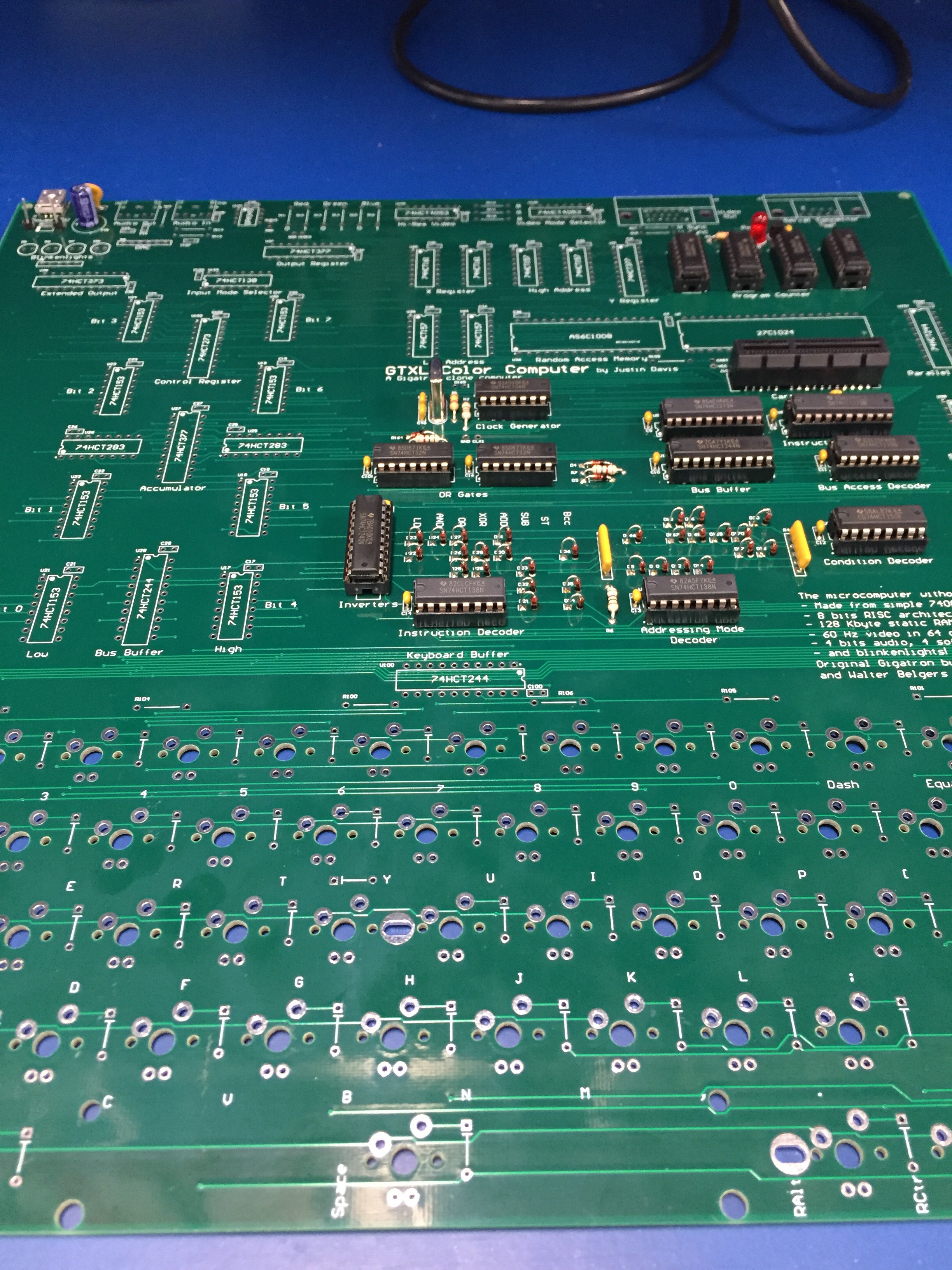
11/28/2018 at 20:30 • 4 commentsI have everything but the keys and diodes are soldered on. The board should be able to run the ROM code. Except it doesn't. I burned the ROM and it doesn't seem to be running the code. It does appear to be running SOME code, but not the correct code. I'm wondering if I perhaps burned the ROM incorrectly. I need more time to investigate, but it does not execute the first few instructions which can easily be probed on the board. I can read the code back off the ROM, so I know it's burned. I'll need to decode each instruction to verify it's correct, but more time is needed which I have very little of lately. I need to retire so I can have more fun with hobbies. Unfortunately I have at least another 20 years to go...
![]()
-
Building
11/14/2018 at 13:01 • 4 commentsStill building - not quite to blinking lights yet. Lots of soldering. I ran out of 20-pin sockets, so I had to put some on order. I also didn't realize I had no 750 Ohm resistors. I've also been seeing if there's a drop-in ZIF socket for the ROM, but I haven't found one yet. I probably should have thought of that during layout. It may help if I do lots of ROM updates. More likely I will just build the cartridge with reprogrammable memory.
While I'm waiting I can start loading chips and testing starting with the ALU and then the X/Y registers. I'll wait for the Cherry MX keys until I have everything else checked out since they are fairly expensive (at 63 of them are).
![]()
-
Build update
11/01/2018 at 16:04 • 4 commentsI've been building the GTXL one step at a time and checking as I go. So far, the power system, clock, program counter, IR/D registers, and control system is working.
I made one mistake with the diodes. The artwork is reversed, so I installed all the diode backwards. Installing (and removing) those diodes is pretty time-intensive, so it set me back quite a bit. But everything else is ok so far.
I'll probably do the ALU next followed by the X/Y registers. I want to build up and test all of the existing functionality before I move on to the added functions.
![]()
-
PCBs are in
10/19/2018 at 12:37 • 0 commentsI received my PCBs today from PCBWay. The Gigatron guys gave me a coupon to use for the board which made them FREE (thanks guys!). I've ordered maybe a dozen designs from PCBWay before, and I've never had any problems. Hopefully the tariffs don't make the price go up too much because they have always had great prices and great quality.
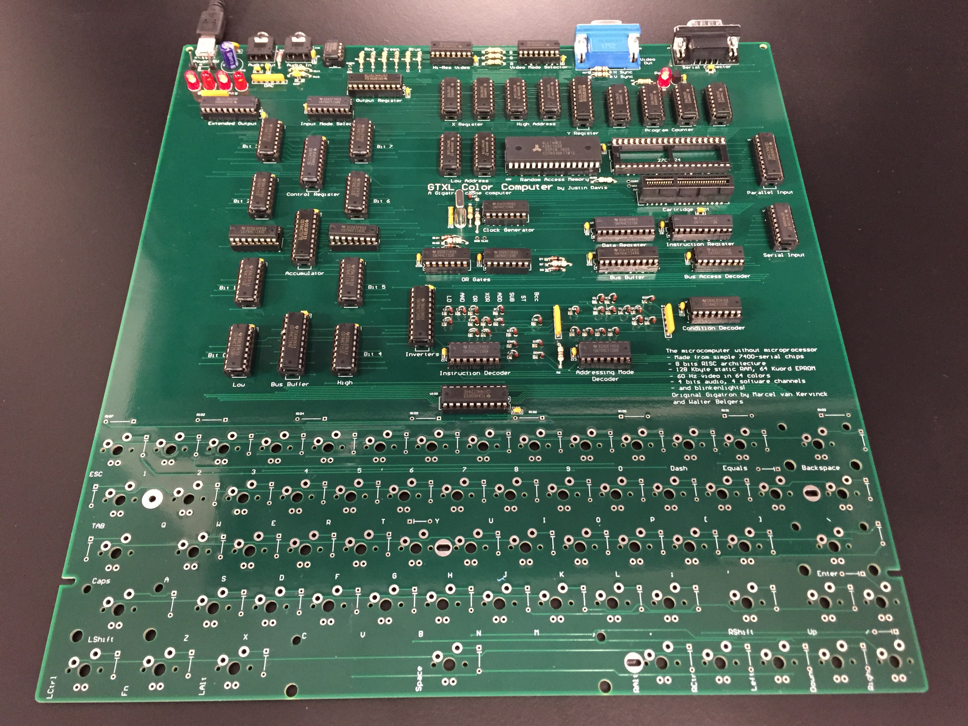
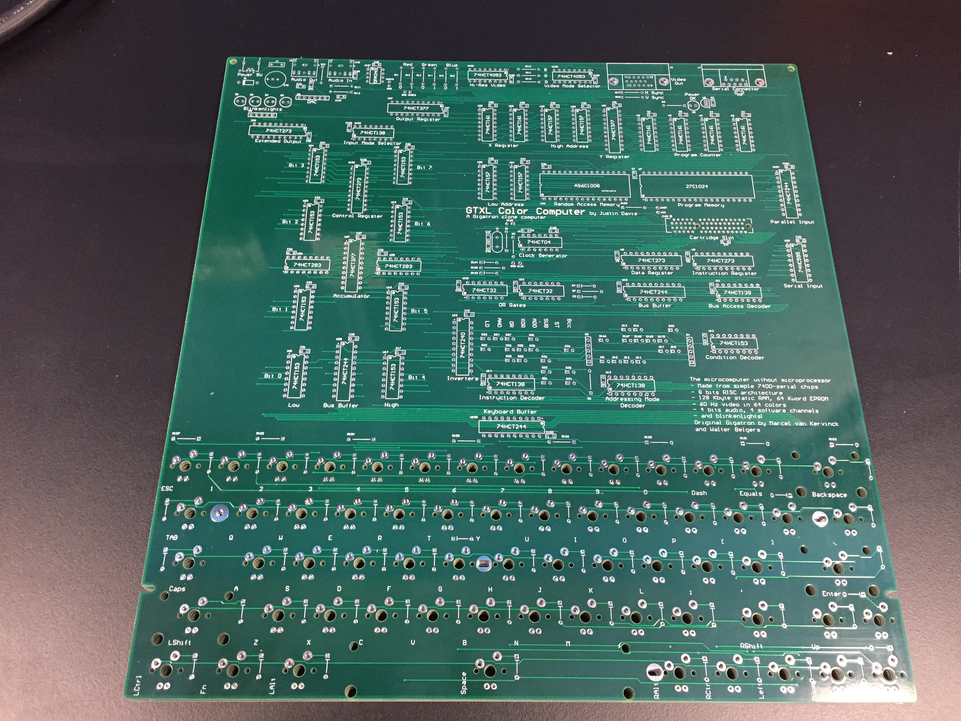
They look good on first inspection. They feel larger than I was expecting. It's probably the largest board I've ever made, but I wasn't exactly trying to minimize the space. The width of the keyboard set that dimension, but I could squeeze the length. I wanted to keep the same component layout so it looks the same as the original Gigatron. I don't expect there to be a big demand for this, so these might be the only 5 boards that I get made.
Now I just need some time to assemble. I think I have all the parts for it. I was planning on using sockets for everything since this is a prototype just in case I have rewire things.
![]()
-
Cartridge design
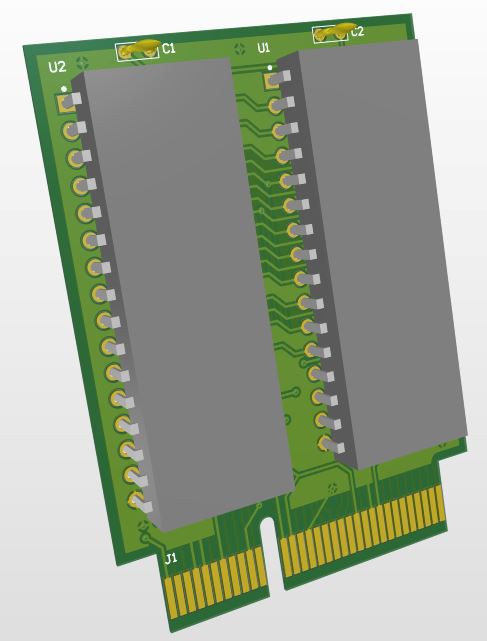
09/28/2018 at 17:12 • 0 commentsI've made a cartridge which matches the slot to verify the pinout. It has two flash chips. It's a little bigger than I expected, but that's because of the DIP through-hole packages. I could probably make a much smaller one with surface mount memories. But it's cool. I may have to make a programmer board for it.
![]()
-
Cartridge port
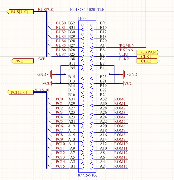
09/24/2018 at 14:48 • 0 commentsI wanted to have a cartridge port to make it easier to load new programs into ROM. It also makes it more like old Commodore 64 or Atari 400/800 computers. I don't think there will be many cartridges made, but I like to think that it's possible. I also want to be able to pop out the cart and reprogram it easily without modifying the computer itself. When the cart is inserted, the /ROMEN line is forced high by the cart which disables the internal ROM. I also included the data bus, clocks, and an /EXPAN input which is enabled with /IE just in case someone comes up with a good idea.
I chose an edge connector that is keyed so that it's not possible to plug the cart in backwards.
-
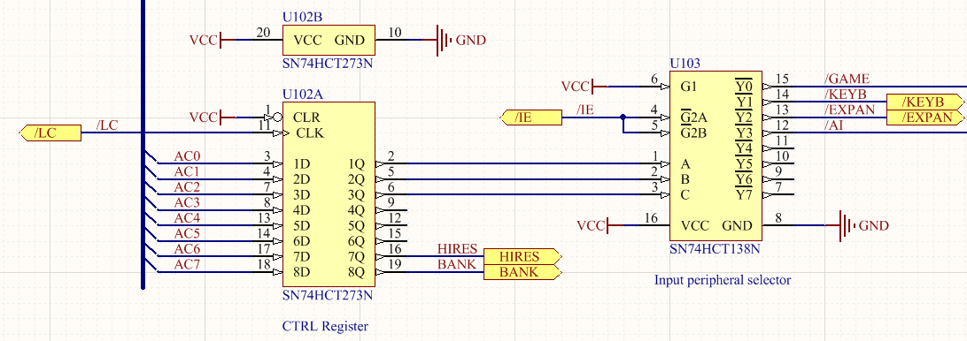
Keyboard interface
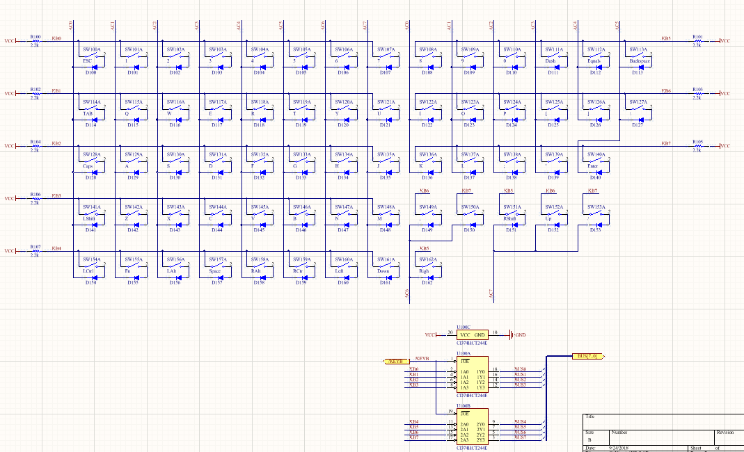
09/24/2018 at 14:20 • 0 commentsWith the control register, I can change the functionality of the input select line. Previously /IE would select the serial input chip for the gamepad controller. That's still the default behavior, but it can be changed to select a different input peripheral. My main goal was to add a built-in keyboard, so I started with a simple keyboard matrix. The AC line selects the column, and then a ST IN -> [X,Y] stores the row information to RAM. AC should only set one bit low at a time while the others will be high. This will take 8 reads from the keyboard to see which keys are pressed. This is relatively software intensive, but only costs one CMOS chip (a bus buffer). This style allows many more possibilities for functionality. It should also be immune to ghosting from multiple key presses due to each key having its own diode.
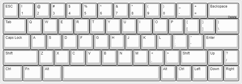
This limits us to 64 keys, but that's ok. I came up with a layout of 63-keys that includes arrow keys.
![]()
I prefer a good mechanical keyboard to simulate a good old 70s/80s computer. It's more expensive than other options, but it has a great feel to it. I used the GH60 open-source keyboard layout design as a reference and is compatible with the Cherry MX keys. The arrow keys are not on the GH60, so it's not exactly the same. And I didn't put in the options for alternate key mounting.
-
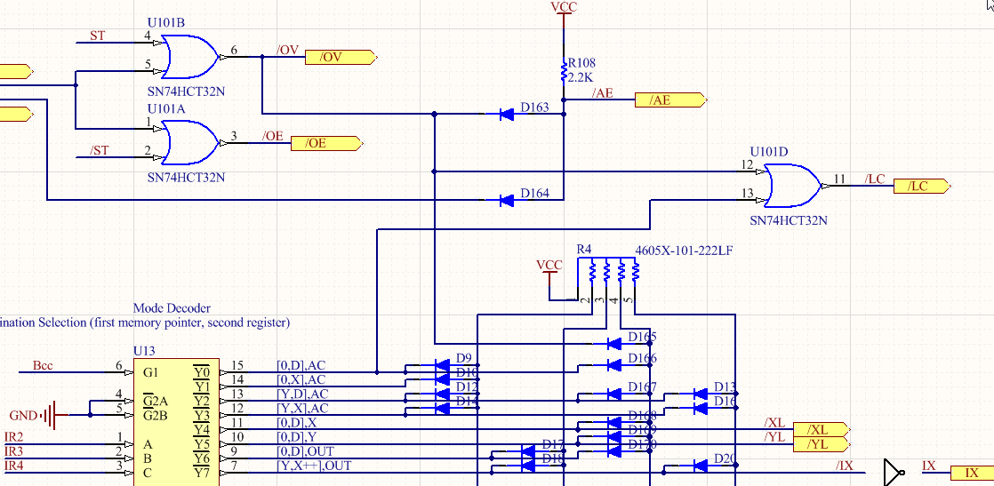
Control register
09/24/2018 at 14:00 • 0 commentsI need to have another control register to control the new functions. This register controls the hi-resolution mode, the keyboard access, the cartridge access, the bank switching of the RAM, etc. I don't want it to get modified unintentionally, so I need it to be tied to the new instruction calls. This is not too difficult, because I can use the /OVerride signal to drive it. But I don't want all the /OVerride instructions to call it, so I chose to use one of the instructions ST AC->[0,D] and /OVerride to load the control register /LC. Much like XOUT, the CTRL register loads from the AC register. And at the same time, AC is stored to RAM at [0,D], so the programmer needs to be a little careful.
/LC = /OV or [0,D],AC
likewise, /LC = /OV or (/IR2 and /IR3 and /IR4)
GTXL Gigatron clone computer with keyboard
Microcomputer that runs without a CPU