-
So close...
08/22/2019 at 20:26 • 4 commentsI've updated my Arduino code so that I can stream the ROM code to it and load it into my flash cartridge. This will hopefully make coding go faster now that I can use the python assembler and not have to write machine code by hand. I'm still using the ROM v3 code, but I can update to v4 soon.
I notices in the ROM code it takes quite some time to get through the boot sequence with verifying the memory. Since I'm still using the Arduino to drive a slower clock to the board, I had to change that to pump up my clock speed. So after hacking the internal timers to fast PWM mode, I can now get from 7kHz up to 8MHz. Unfortunately I can't get the exact 6.125MHz I need for video, so at some point I'll have to put the clock chip back in.
I've found I have 3 LEDs come up in sequence which means the memory checks are succeeding. The 4th LED does come on, but it blinks at a very high rate. I had to slow the clock down to see it. At about 125kHz it's noticable. It does not do the LED scroll sequence, so it is still having some problem somewhere in the code.
I also noticed I have to manually issue a reset to the board after it powers up usually to get the code running. I'm not sure why, but I'll have to look into that. It's possible my bank switching is powering up at 1 which would start running code in the wrong bank. I suppose I could add a piece of code at the beginning of the top bank so that if it ever boots there it will bump it over to the correct bank and continue booting. But I feel like it's REAL close to running.
-
Fibonnaci checks out
08/15/2019 at 12:21 • 3 commentsWell, I should have expected the Fibonacci code to work since I already checked out all the previous functions of it. So I'm wondering what isn't going to be working to prevent the ROM code from working. I'm running the ROM v3 code because I'm worried about the ROM v4 code is incompatible. I noticed the new bus expansion board uses the same instruction set hack that I used - it uses the same invalid memory instructions to talk to the expansion board as I use to talk to my control registers. The v3 does not use these instructions, so it should run ok.
So I'm starting to really scratch my head on what the problem could be here. I'm starting to think it may be a clock problem - all the code that runs slowly works correctly. So next I may try to slowly run the rom code and see if it works. All I really need to see is the 4 LEDs turn on one at a time to show the board has booted. I need to modify my Arduino flash loader to read the ROM file and dump the whole thing into the flash cartridge.
// Fibonacci series // $[00] = a // $[01] = b // $[02] = tmp byteProgram(0x0000, 0x0000); // ld $00 ; outer loop byteProgram(0x0001, 0xc200); // st [$00] ; a=0 byteProgram(0x0002, 0x0001); // ld $01 ; b=1 byteProgram(0x0003, 0xfc0a); // bra $0a byteProgram(0x0004, 0x0200); // nop ; (pipelining) // inner loop start byteProgram(0x0005, 0x0100); // ld [$00] byteProgram(0x0006, 0xc202); // st [$02] ; tmp=a byteProgram(0x0007, 0x0101); // ld [$01] byteProgram(0x0008, 0xc200); // st [$00] ; a=b byteProgram(0x0009, 0x8102); // adda [$02] byteProgram(0x000a, 0xc201); // st [$01] ; b+=tmp byteProgram(0x000b, 0x1800); // ld 0x00, OUT ; Prepare XOUT update, hSync goes down, RGB to black byteProgram(0x000c, 0x1840); // ld 0x40, OUT ; hSync goes up (bit 6), updating XOUT and blinkenlights byteProgram(0x000d, 0xf405); // bge $05 ; repeat if bit7 is still 0 byteProgram(0x000e, 0x0200); // nop ; (pipelining) // inner loop end byteProgram(0x000f, 0xfc00); // bra $00 ; start over again byteProgram(0x0010, 0x0200); // nop ; (pipelining) // output: //0 0000 0000 //1 0000 0001 //1 0000 0001 //2 0000 0010 //3 0000 0011 //5 0000 0101 //8 0000 1000 //13 0000 1101 //21 0001 0101 //34 0010 0010 //55 0011 0111 //89 0101 1001 //144 1001 0000 -
RAM is go!
08/14/2019 at 15:36 • 0 commentsThe RAM appears to be working ok. I haven't done an exhaustive test, but I'll get to that soon. I just wanted to make sure I could read/write using the legacy memory modes. I haven't checked out the new memory access modes yet. So I'm getting low on the things which may not be working. This means I may have to try more intricate tests. I figure why not try the fibonacci code with a slight modification. It would be slightly more interesting and use the RAM a little more.
// RAM tester byteProgram(0x0000, 0x0000); // ld (0b0000, AC) // value to load into blinkenlights LEDs |OOOO| byteProgram(0x0001, 0x1800); // ld (0x00, OUT) // Prepare XOUT update, hSync goes down, RGB to black byteProgram(0x0002, 0x1840); // ld (0b01000000, OUT) // hSync goes up (bit 6), updating XOUT byteProgram(0x0003, 0xC005); // st 0x05 [0x05] // write to RAM [0,D] where d=5 a value of 0x05 byteProgram(0x0004, 0x0105); // ld [0x05], AC // read from RAM [0,D] where d=5 to AC byteProgram(0x0005, 0x1200); // ld (ac,x) // move AC to X byteProgram(0x0006, 0x1800); // ld (0x00, OUT) // Prepare XOUT update, hSync goes down, RGB to black byteProgram(0x0007, 0x1840); // ld (0b01000000, OUT) // hSync goes up (bit 6), updating XOUT and blinkenlights expect: |*0*0| byteProgram(0x0008, 0xC40A); // st 0x0A,[x] // write to RAM [0,X] a value of 0x0A byteProgram(0x0009, 0x0500); // ld [x] // read from RAM [0,X] to AC byteProgram(0x000A, 0x1600); // ld ac,y // move AC to Y byteProgram(0x000B, 0x1800); // ld (0x00, OUT) // Prepare XOUT update, hSync goes down, RGB to black byteProgram(0x000C, 0x1840); // ld (0b01000000, OUT) // hSync goes up (bit 6), updating XOUT and blinkenlights expect: |0*0*| byteProgram(0x000D, 0xC803); // st 0x03,[y,0x03] // write to RAM [Y,D] at 0x03 a value of 0x03 byteProgram(0x000E, 0x0903); // ld [y,0x03] // read from RAM [Y,D] where d=0 to AC byteProgram(0x000F, 0x1800); // ld (0x00, OUT) // Prepare XOUT update, hSync goes down, RGB to black byteProgram(0x0010, 0x1840); // ld (0b01000000, OUT) // hSync goes up (bit 6), updating XOUT and blinkenlights expect: |**00| byteProgram(0x0011, 0xCC0E); // st 0x0E,[x,y] // write to RAM [Y,X] a value of 0x0E byteProgram(0x0012, 0x0d00); // ld [y,x] // read from RAM [Y,X] to AC byteProgram(0x0013, 0x1800); // ld (0x00, OUT) // Prepare XOUT update, hSync goes down, RGB to black byteProgram(0x0014, 0x1840); // ld (0b01000000, OUT) // hSync goes up (bit 6), updating XOUT and blinkenlights expect: |0***| byteProgram(0x0015, 0xFC00); // bra (0x00) // unconditional branch back to 0 byteProgram(0x0016, 0x0200); // nop // nop for pipelining simplification -
ALU is go
08/06/2019 at 20:16 • 0 commentsFinished the next check-out program and the ALU is working. It isn't an extensive checkout - just enough to make sure my control logic is good. I also put together a quick clock program on my Arduino to toggle the clock at about half a second. So the lights changed slowly enough for me to verify the outputs were good. I also checked the branch-if-equal-to-zero command. I have to admit I kinda like writing machine-code. At least for small test programs. Next up will probably be writing and reading the RAM. There's several different ways to access the memory and I did a lot of modifications to the MAU. I wouldn't be surprised if there are problems here.
// Program to test ADD, SUB, AND, OR, XOR functions of ALU byteProgram(0x0000, 0x000F); // ld (0b1111, AC) // value to load into blinkenlights LEDs |****| byteProgram(0x0001, 0x1800); // ld (0x00, OUT) // Prepare XOUT update, hSync goes down, RGB to black byteProgram(0x0002, 0x1840); // ld (0b01000000, OUT) // hSync goes up (bit 6), updating XOUT and blinkenlights // top of loop: byteProgram(0x0003, 0xF00A); // beq (0x0A) // branch if equal to zero to exit loop byteProgram(0x0004, 0x0200); // nop // nop for pipelining simplification byteProgram(0x0005, 0xA001); // sub (0x01, AC) // sub 1 from AC register byteProgram(0x0006, 0x1800); // ld (0x00, OUT) // Prepare XOUT update, hSync goes down, RGB to black byteProgram(0x0007, 0x1840); // ld (0b01000000, OUT) // hSync goes up (bit 6), updating XOUT and blinkenlights byteProgram(0x0008, 0xFC03); // bra (0x03) // unconditional branch back to top of loop byteProgram(0x0009, 0x0200); // nop // nop for pipelining simplification // exit loop: byteProgram(0x000A, 0x4005); // or (0x05, AC) // test OR function (expect 0x05 result) |*0*0| byteProgram(0x000B, 0x1800); // ld (0x00, OUT) // Prepare XOUT update, hSync goes down, RGB to black byteProgram(0x000C, 0x1840); // ld (0b01000000, OUT) // hSync goes up (bit 6), updating XOUT and blinkenlights byteProgram(0x000D, 0x600F); // xor (0x0F, AC) // test XOR function (expect 0x0A result) |0*0*| byteProgram(0x000E, 0x1800); // ld (0x00, OUT) // Prepare XOUT update, hSync goes down, RGB to black byteProgram(0x000F, 0x1840); // ld (0b01000000, OUT) // hSync goes up (bit 6), updating XOUT and blinkenlights byteProgram(0x0010, 0x200C); // and (0x0C, AC) // test AND function (expect 0x08 result) |000*| byteProgram(0x0011, 0x1800); // ld (0x00, OUT) // Prepare XOUT update, hSync goes down, RGB to black byteProgram(0x0012, 0x1840); // ld (0b01000000, OUT) // hSync goes up (bit 6), updating XOUT and blinkenlights byteProgram(0x0013, 0x8001); // add (0x01, AC) // test ADD function (expect 0x09 result) |*00*| byteProgram(0x0014, 0x1800); // ld (0x00, OUT) // Prepare XOUT update, hSync goes down, RGB to black byteProgram(0x0015, 0x1840); // ld (0b01000000, OUT) // hSync goes up (bit 6), updating XOUT and blinkenlights byteProgram(0x0016, 0x80FD); // add (0xFD, AC) // test ADD function (expect 0x06 result, should rollover) |0**0| byteProgram(0x0017, 0x1800); // ld (0x00, OUT) // Prepare XOUT update, hSync goes down, RGB to black byteProgram(0x0018, 0x1840); // ld (0b01000000, OUT) // hSync goes up (bit 6), updating XOUT and blinkenlights byteProgram(0x0019, 0xFC00); // bra (0x00) // unconditional branch back to 0 byteProgram(0x001A, 0x0200); // nop // nop for pipelining simplification -
Blinkenlights working!
08/05/2019 at 20:14 • 1 commentMy second program only turned on and off the blinkenlights and they are working. This means the OUT and XOUT registers are working (and that I placed the LEDs in the right spots). I also did a quick check on the X register and that is working as well. At this point I wish I had included a reset button.
I'd like to get away from single stepping the clock since it is kind of tedious. I'd like to make some kind of delay function which will let me see the LEDs with the clock running at full speed. I'm not sure if I can because I'd need a delay in the millions of clock cycles. And I need to verify at least the add function. And the conditional branch too. I'd need to store the counter value in RAM and I haven't verified that yet either.
OR I just feed it a very slow clock. That sounds easier.
So next I step through a simple count-up program. And do a conditional branch at the end. And then maybe do some logic functions on the AC register - XOR, AND, OR. And then maybe do a count-down program with different conditional branch.
-
First program fully operational
07/30/2019 at 20:08 • 0 commentsLooks like the last solder fix did the job and the first program is now running fully. I put the official ROM back in and I did not see the blinkenlights running like they are supposed to. So I'm guessing there's more problems. I've verified I can load the AC, Y, and PC registers with the correct data. Next I think I will write a simple program to verify the blinkenlights since that's my check that the ROM is working. That will verify the OUT register and XOUT register. I supposed I could throw in an instruction to load X to verify the X registers are working right as well.
After that I may start checking the ALU using the blinkenlights. Since I'm single stepping through the program, I can see the lights fairly easily and it saves me from having to probe every pin on every device to verify the ALU output bus. Kind of the purpose of blinkenlights, wouldn't you say?
-
Branching success!
07/30/2019 at 00:00 • 0 commentsI found a few more problems with the board. I had tied the RAM WE to the cartridge, but I connected it to the flash ROM's WE which I think was screwing it up. I cut that trace, and then put pullups on the /WEs to the flash ROMS. The flash ROM then starting putting out the correct data. And right after that, the small test program started to correctly branch and go around the short loop.
However, I checked the load instructions and that is not working. I checked the input and output at the /LD gate, and the input is not toggling. However, the ROM diodes which feed into the gate are toggling. I checked connectivity and for some reason the trace is not connected from the diodes to the chip pins. I checked the layout and it is connected correctly in CAD. Looking at the trace looks good too. But I ran out of time again, so it's a problem for tomorrow. So close for the first test program running!
update: I found the problem - when I had to reverse all of my diodes, one of the traces broke right at the pad. I had to use the high power microscope to find it. So I just scraped some solder resist off of the trace and soldered to it. Connectivity restored! I'll check the functionality later today.
-
Reversed ROM bytes
07/27/2019 at 14:17 • 0 commentsI got the program stepping through one instruction at a time so I could probe all my lines. First thing I found out is that my bytes are swapped coming out of my ROM. I didn't realize that the instruction was the lower byte and the data was the upper byte. Of course it's obvious in the schematic, but I didn't put that together with the software. I reprogrammed by flash ROM pretty quickly, but it still didn't run as expected. For some reason after reprogramming, the ROM started to refuse to put out anything. I put it back into my Arduino programmer, and it could read the values, so I'm not sure what changed. I ran out of time, so that all for today. I'll need to put more time into it. But at least I'm knocking out problems one by one.
-
Small program no-go
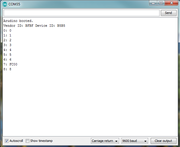
07/26/2019 at 16:38 • 3 commentsWell, the short program did not execute as predicted. The program got stuck constant executing a jump instruction back to the same instruction. This makes sense if most of the memory is filled with all 1s - FFFF. I could see both clocks running. I will have to manually step through the instructions by controlling the clock. Or manually feed instructions to verify they are being decoded correctly. I know it is jumping because the program counters are being loaded, but I'm not sure if the correct location is being loaded.
I will also need to check to see the initial state of the Y register. I assume it is powering up as all 0s. If it powers up as all 1s, then when it gets to the branch instruction, it will jump to 0xFF00 instead of 0x0000. I wonder if maybe I should add one extra instruction to load the Y register with 0x00 to ensure it will jump back to 0x0000. I believe the machine instruction is 0x1400 (ld [D],Y) which I will put in address 1 so the new program would be:
  byteProgram(0x0000, 0x0000);
  byteProgram(0x0001, 0x1400);
  byteProgram(0x0002, 0x0002);
  byteProgram(0x0003, 0x0003);
  byteProgram(0x0004, 0x0004);
  byteProgram(0x0005, 0x0005);
  byteProgram(0x0006, 0x0006);
  byteProgram(0x0007, 0xfc00);
  byteProgram(0x0008, 0x0008);
-
Slooooow progress
07/25/2019 at 12:02 • 1 commentI have had very little time to put into the project, but it is still my highest priority personal project. I had to respin both the cart and the programmer board because of errors. But I do have the cart able to store and readback a simple program. Since my gigatron is not correctly running code yet, I loaded the first program the original gigatron ran into the flash cartridge - just simple loads and a jump as recommended by Marcel. I have just finished verifying it on the cart, and need to analyze it running on the gigatron.
https://hackaday.io/project/20781-gigatron-ttl-microcomputer/log/58830-first-program-run
I also found a few schematic errors because I did not copy the gigatron project exactly. I fixed those on the gigatron by cutting traces and soldering jumper wires, but that did not immediately solve my problems. So next up is functional testing with the custom code.
GTXL Gigatron clone computer with keyboard
Microcomputer that runs without a CPU