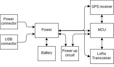
Now that I have my requirements set up, I can plan my circuit using a block diagram (fig. 1).

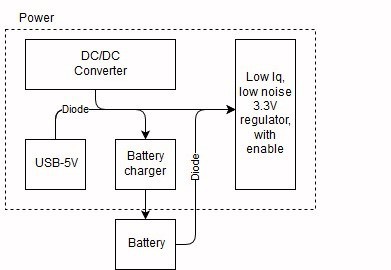
The power circuit is fed in 2 ways: 5V from an micro-USB connector (also used for programming and configuration) and whichever voltage comes from the drone's power system. The power block is detailed in fig. 2. It contains:
- a DC/DC converter that steps down the voltage to 5V. The converter 5V is separated from the USB 5V using 2 Schottky diodes.
- a battery charger. Since all electronics run on 3.3V, a single LiPo cell is enough. The charger will be of linear kind, with low charging current (the battery will also be small), compatible with PC USB ports (max 500mA current draw).
- The battery is also connected with a diode for fast switch-over in case the other sources disappear. It would be nice if the battery included its own cutoff board (such as the CX-10 mini-quad battery)
- a 3.3V, low quiescent current LDO, with enable input. I do not intend make use of the MCU's deep sleep modes instead of a hard shut-down. This way, I can also take advantage of the GPS' module low power tracking mode. It would be nice if I could fine one that also has low noise. Generally, the GPS receivers are quite sensitive and usually require less than 10 mV peak-to-peak noise on the power input.

I haven't thought at the power up circuit yet, but it will certainly have something to do with a momentary push button and the micro-controller.
The MCU will be of ultra-low power type, most likely a STM32L0 with the smallest available package (except BGA and chip-scale package). USB peripheral would be nice, it could make the micro-USB connector more useful (for configuration and possibly firmware update). This block also includes everything a MCU needs: reset pull-up and capacitor, configurable boot mode (depends on the MCU), an "alive" led, decoupling capacitors and, obviously, a programming connector (probably smd pads to solder wires).
I will search for the smallest GPS receiver available, with low power tracking modes. Power down options (other than power cutoff) are also required, and most likely, will be an Enable pin, driven by the MCU.
I already selected the radio module: RFM96. It is a LoRa transceiver, operating in the 433MHz band. Apart from LoRa, it also knows FSK modulation, so it might be possible to send some audio, but that's a feature for the far away future. The antenna will be attached with a UFL connector.
Now let's find some real world components!
Discussions
Become a Hackaday.io Member
Create an account to leave a comment. Already have an account? Log In.