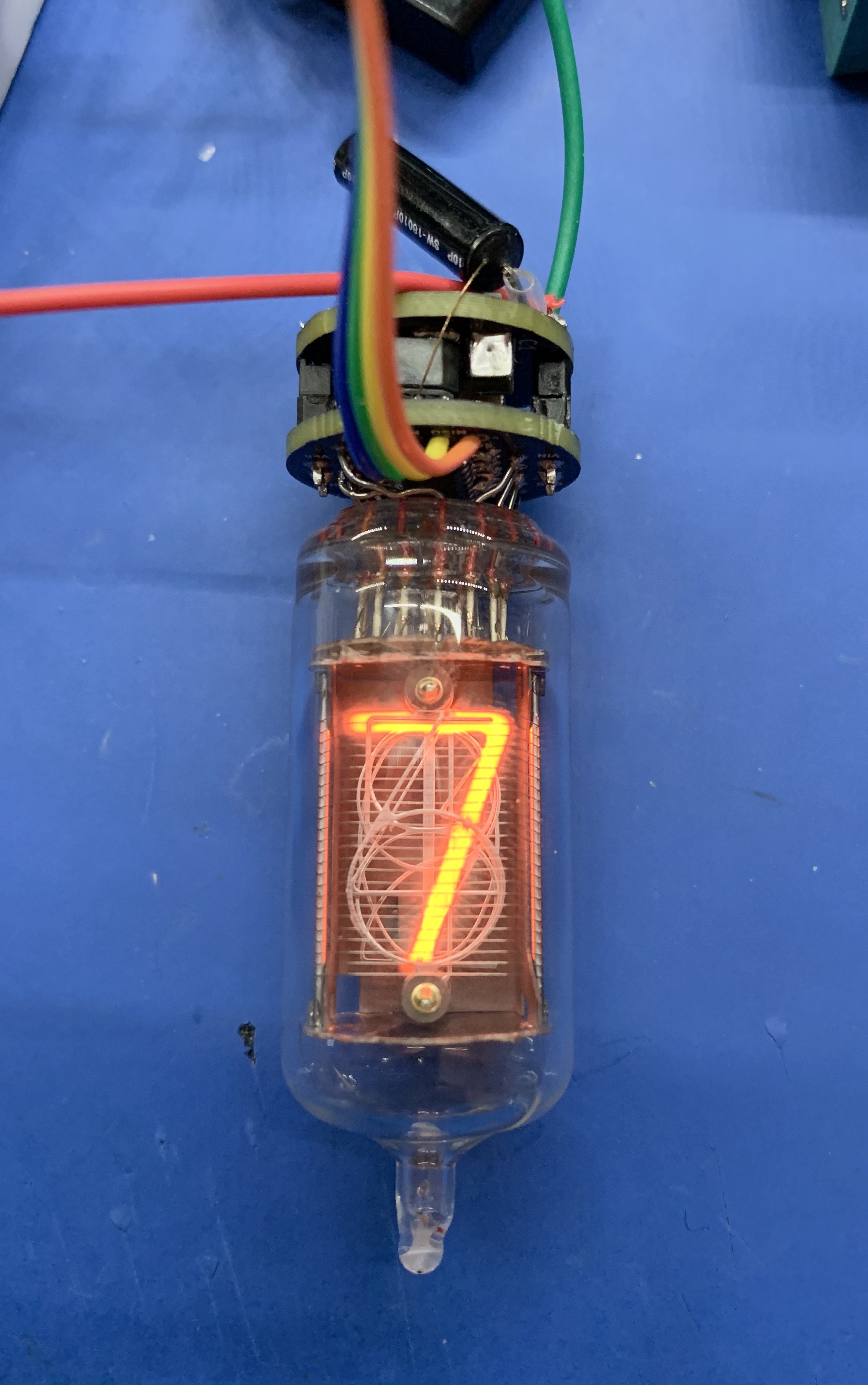
I decided that I would add a motion sensor to the pendant. I bought some SW-18010P high-sensitivity vibration sensors, which are mechanical devices, and I added one to the device and created code that would turn the display off a certain time after the last movement was detected. That is when I discovered that disabling the HV wasn't working. By this time, I had soldered everything together into its final configuration, so my debugging options were limited. I uploaded the code to a DIP ATTINY84A I had and checked that the appropriate pin was being set correctly using an LED. It was, so the problem lay with the hardware. When I checked some continuity between the HV enable pin and a few other points on the board and discovered that the resistance between the pin and ground was only 100 Ohms - in other words it was being stongly pulled to ground and the ATTINY couldn't raise it to VCC. I have no idea why it is pulled to ground, and I can't fix it anyway, so I changed the code to just blank the display. This is not as ideal as actually switching the HV off altogether, but it will conserve energy.
I also discovered that the vibration switch is not that sensitive and it needs quite a tap to trigger it. Gradual movements don't close the switch. However, this gave me the idea of adding controls using a sequence of taps to move between modes, like turning it on, turning it off, turning it on permanently, turning it on with a delay etc. However, I'm not altogether sure I want the vibration switch on there anyway - it is quite large (it is the black cylinder in the photograph below).
If I was starting again, I would add an accelerometer to the main board, but that would mean I would also have to go to four layers, which I would definitely do.
Anyhow - here is the latest picture - it is still tethered to the programmer with a ribbon cable. The green and red wires connect it to the battery:

 Paul Andrews
Discussions
Become a Hackaday.io Member
Create an account to leave a comment. Already have an account? Log In.