helge
helge-
Laser-Cut Plate Stack 8-way Valve
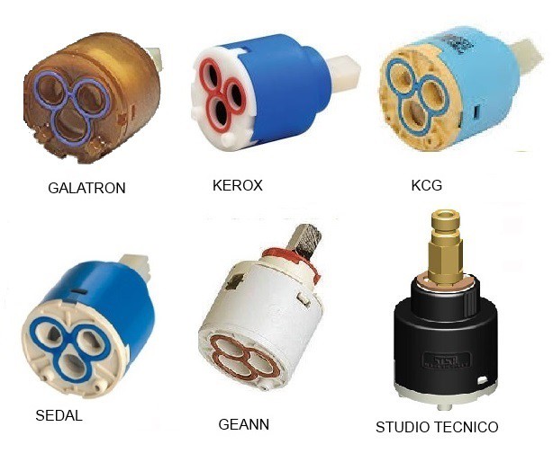
09/29/2018 at 19:45 • 0 commentsIt's almost certain that you've used a plate stack valve before - they are made of lapped alumina plates and found in many faucets.
![]()
inside there's a set of ceramic plates with channels. These are made by dry-pressing ceramic powder with a binder and subsequent firing to sinter the particles.
![]()
To achieve precise dimensions the parts have to be lapped afterwards. It's interesting to note that for these very hard and brittle materials sustained wear occurs down to surface roughness / waviness in the order of 10 nanometers - so basically these plates will wear just as everything else but do so very, very slowly at the minute sealing pressures involved. (Reference: https://www.nature.com/articles/ncomms11816)
Here's a video from This Old Tony where one of them is being serviced.
Lubrication is also an important factor in wear processes, but for the scope of our discussion we'll just mention the inevitability of wear, prompting the question what materials and operating conditions to select to minimize it. Also note that soft materials will have harder particles like rust flakes embedded in their surface when contaminated, changing the wear mechanism from frictional / adhesive wear to more severe abrasive wear.Acrylic Plate Valves
It's not too far-fetched to try and make plate valves oneself. They key to success is surface flatness and preload, both of which seem easy to achieve at first glance but soon descend into manufacturing hurdles and principal limitations.
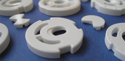
Cast polymethylmethacrylate (PMMA) being a soft yet somewhat brittle plastic can be water jet cut, but lacking the capabilities, can also be neatly processed using a laser cutter while retaining most of the appealing properties of plate stock - smooth surfaces, consistent thickness and coplanarity. The problems come with the heat-affected zone though.
![]()
"When the laser beam is moving across the workpiece surface,
it creates a pool of molten polymer in a spot where it impinges
on the surface. The pool is driven away from the hot spot into all
directions by the heated gases of the vaporizing plastic, while
most of the melted material is resolidifying in the wake of the
beam."Source: http://citeseerx.ist.psu.edu/viewdoc/download?doi=10.1.1.464.6609&rep=rep1&type=pdf
This is what one would expect from a laser cut feature - mostly ablation and a small heat-affected zone.
Experimental Results
Let's start with the aftermath of a laser cut (here: ~100W CO2)
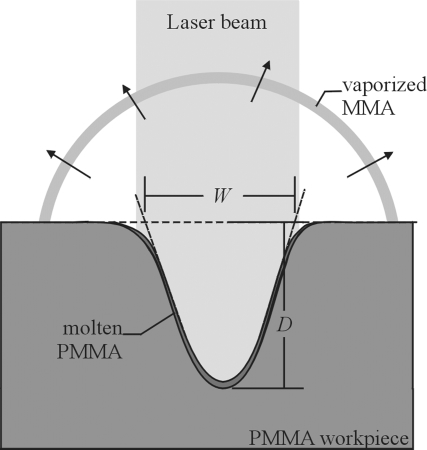
Here's a picture of laser-cut PMMA made with 90° crossed polarizers. The bright areas are caused by stress-induced birefringence - this generally makes the polarization somewhat elliptical and thus regenerates a component of light that subsequently passes the second polarizer. right: after laser cutting, left: additionally submerged in ethanol, severe solvent crazing and partial relaxation of stresses:
![]()
All edges are laser cut and thus have a thin veneer of rapidly melted and re-solidified PMMA with high internal stresses. The material can be annealed to remove the stresses and they have been found to also dissipate over weeks of storing at room temperature.
What's more bothersome however is that there is a bit of upwelling / raised border around the edges which foil our attempts to use the laser cut parts as is. Now they have to be sanded on both sides, and it's hard to sand soft, locally uneven materials without causing unevenness / waviness across the whole thing. Moving forward with the sanded plates the overall setup conceived here is this:
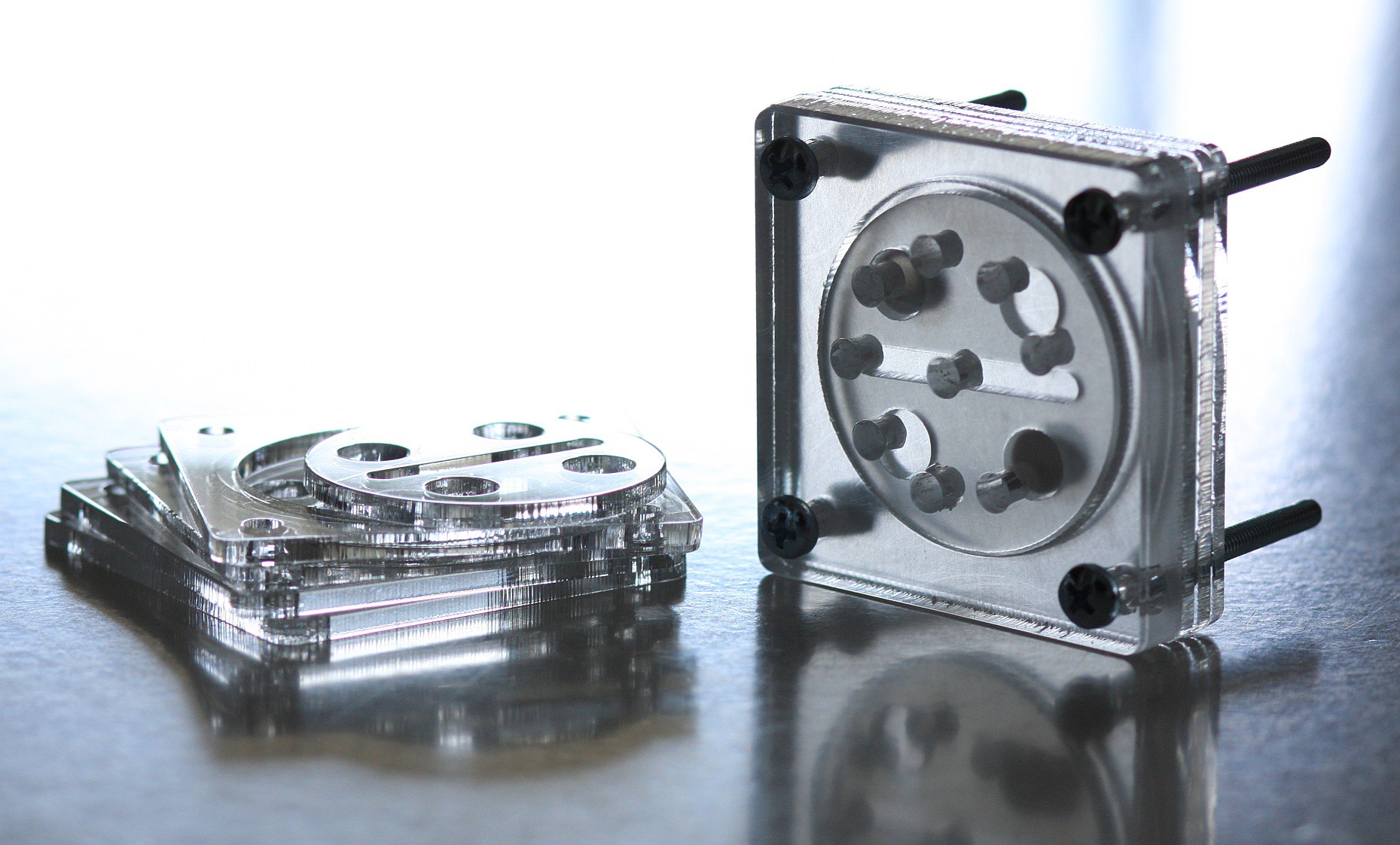
![]()
Water can enter the central hole and flow through the diametral slot. The holes are addressed such that the next hole is 190..200° from the previous one so the distance between the output ports is maximized while the disc only has to be rotated half a turn to address all ports.
Obviously this is done to comply with the capabilites of cheap RC servos while the number of 8 ports also is along the lines of cheap RC servo precision.
Here's a video of the valve block in action with water:
https://www.bitchute.com/video/hF6HtnRLu8it/
The whole valve assembly can be glued shut, the disc is being rotated with a magnetic clutch. This idea isn't new by any means and applied in industrial applications for torque limit / stall protection. For reference here's an RC servo grade implementation:
https://robosavvy.com/store/dagu-magnetic-servo-clutches-for-miniature-servos.html
What's missing: the rotating disc should be pre-loaded towards the front plate, e.g. by using a stainless or plastic spring. In a rotating assembly the center of the disc has the smallest surface distance rubbed across adjacent plates so that's where a spring clip should push up against.Further thoughts on wear.
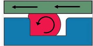
Obviously one might have the urge to add a face seal to the assembly so all ports can be normally closed without fluid leakage or gas ingress. While there are very soft silicone o-rings and even foam o-rings out there, normal EPDM or NBR o-rings are somewhat harder and specified for a certain amount of compression (10-30%) which is rather substantial when considering 3D printed surfaces. Shooting for the low end it remains to be seen whether proper sealing can be achieved.
Dynamic sliding seals of this kind also subject the o-ring to shear forces.
![]()
We've found an implementation along those lines here:
https://www.thingiverse.com/thing:1513456
![]()
And as the creator states, " This is still a project in development , if someone wants to test it and if anyone has any suggestions we might work to create a working and final version.
At this time I have not managed to get a completely no water leaks version . You have to test various configurations of seals."
So maybe using face seals with the much smoother entry sides of laser cut parts might work, especially when adding some sort of highly sticky grease that is stable under water and does not cause solvent cracking in the PMMA.
When using water jet cutting, an array of other interesting materials are within reach and even self-lubricating material combinations become possible (check out Igus DryLin to see it in action, they're using polymers in contact with smooth anodized aluminium rails). Still a design that doesn't rely on un-degraded, non-contaminated sealing surfaces and starts producing high wear once contaminated due to frequent sliding motion seems preferable.
-
the Pump Station
09/29/2018 at 16:37 • 0 commentsDevelop once, deploy many?
Peristaltic pumps shine in a few aspects:
- self-priming
- number of rotations correlates to transported volume = no imminent need for flow metering / gauging
- self-sealing and normally-closed operation
- medium and pump are separated
- no sliding surfaces subject to the medium
but then there's basically the rather sketchy construction unless one breaks out the bearings, spacers and proper geometry.
If you're into building your own peristaltic pumps or haven't seen the ugly details, this video might be helpful.
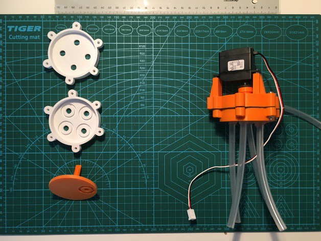
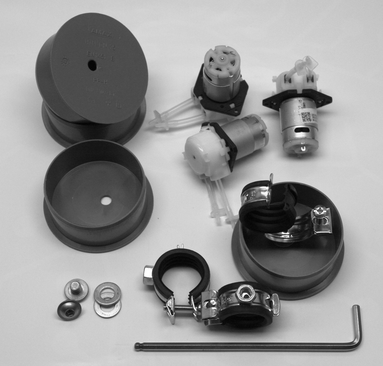
In the post below however we'll be discussing cheap peristaltic pumps from our favourite Chinese e-commerce platform. These pumps don't have a rotor attached to the shaft of the motor. instead, a small brushed motor has a long shaft sticking right into the pump head while three bare plastic rollers are friction driven by the smooth shaft, achieving both a compact design and gearing reduction at the expense of long-term reliability and resilience. Two out of 18 pumps came with collapsed tubing sticking to itself but were subsequently reanimated. One arrived shattered to bits. I guess that's where the term "drop shipping" applies.
Many Pumps
Using many peristaltic pumps surely has its advantages - they are somewhat proven in the field of automated plant watering systems, they're off the shelf parts which can be bought as original parts and replacements from many sources and they interface easily with the rest of the setup in terms of dimenions, tube sizes and voltage / current ratings (e.g. 12V 0.3A).
So let's do that and figure out where the catch really is.
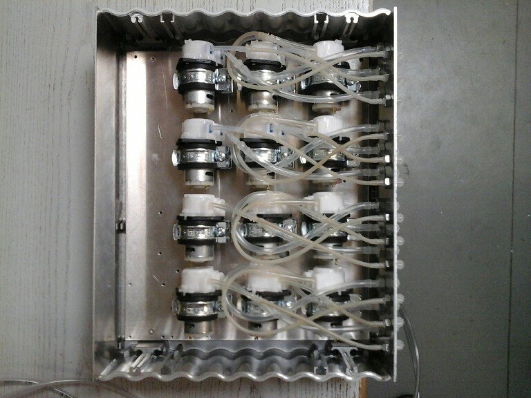
![]()
Obviously the unit shown isn't finished and it isn't finished as of this writing. While we now have an MCP23017 + ULN2003 driver board along with a boost converter to run it offa 5V supply it's hard to ignore the sheer amount of stuff that goes into building one of these pump station assemblies. Each pump is routed to the rear panel so the assembly can also be put to use for mixing fertilizer or pH buffer reagents when moving to hydroponics and related.
It's a bit heavy but other than that it should do the business. It certainly is bulky and will not be as reliable in other orientations, e.g. when stood upright or on the sides so the tubing will hang down and maybe kink. In its natural horizontal orientation it just takes up 35 x 30 cm² of shelf real estate.
Let's talk about cost.In terms of cost this certainly is the most expensive way to water twelve plants, not accounting for uncertainties in the market of chinese parts. Maybe the pumps will cost twice as much in the future, making an array of valves the cheaper option.
Procuring bags of panel mount and straight fittings also adds to the overall joy.
Here's a rough BOM:- 1 enclosure with base plate, drilled and slotted front and back plates
- 12 peristaltic pumps
- 12 pipe clamps with damping
- 12 M8 washers
- 12 ISO 7380-2 M8x8 Socket Flanged Button Screw
- 24 straight barbed fittings 2.4mm / 3.8mm
- 12 90° barbed fittings 2.4mm / 2.4mm
- 12 M6 nuts (plastic, steel) for the 2.4mm fittings
- 12 90° barbed fittings 3.8mm / 3.8mm
- 12 M8 nuts (plastic, steel) for the 3.8mm fittings
- 10 barbed tee fittings 3.8mm to parallel the suction sides
- 2m silicone tube 2/3 or 2/4mm ID/OD
- 5m silicone tube 3/5mm or 4/6 mm ID/OD
- control and indicator electronics
The 40-50 holes with various diameters don't layout, drill and countersink themselves either.
Let's call this piece of engineering "lab equipment".
-
IoP Satellite - pump head
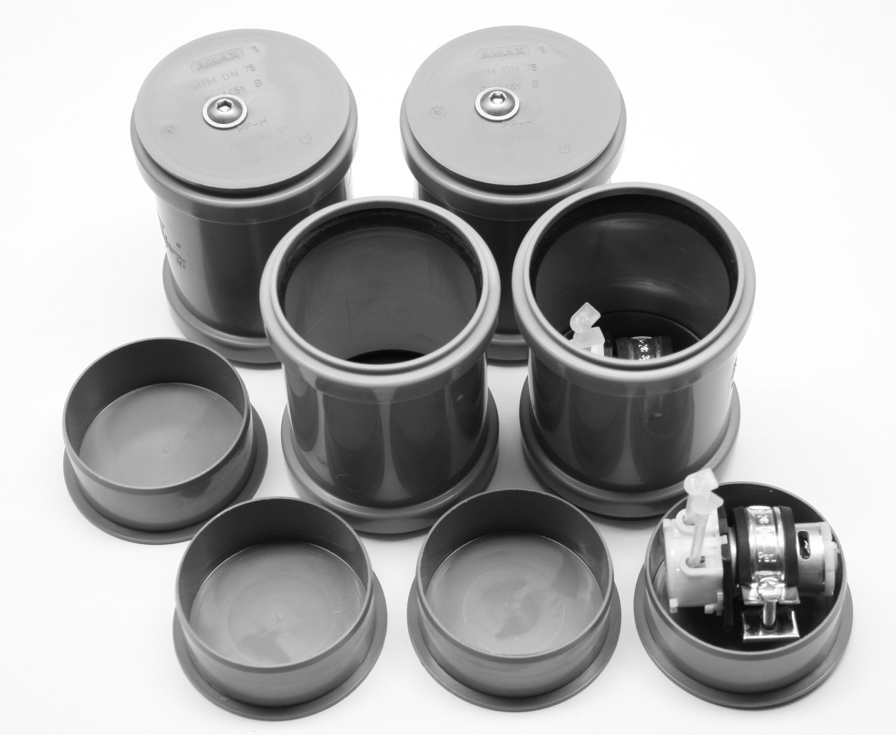
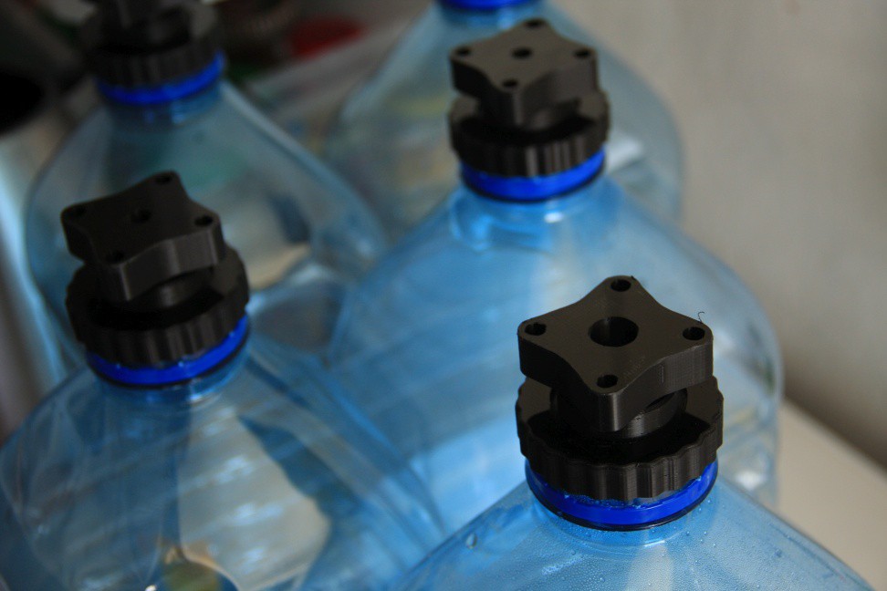
09/29/2018 at 14:37 • 0 commentsHere's what was supposed to be the initial concept for a plant automation system. A pump / control head is mounted to a reservoir with 1.5 .. 20 L volume. The head contains a small brushed motor peristaltic pump in a pipe clamp with vibration damping.
![]()
The enclosure is made of DN75 pipe couplers and end caps which are easily available. A few 3D printed parts hold electronics and battery and connect to the reservoir vessel.
![]()
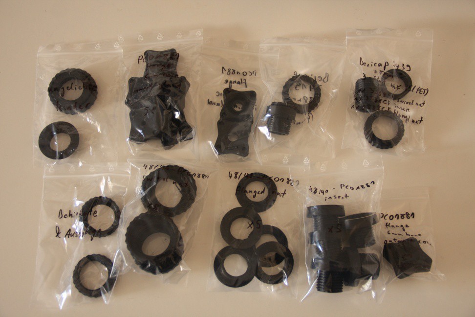
It turns out that there's a plethora of different neck finishes for PET bottles. Less so with canisters where neck finishes like 48/41, DIN45, DIN51, DIN61, ..are commonly encountered, at least for the 3+ L ones. The smaller PET bottles often come with PCO-1881 but then again there are lots of different other finishes out there with deviating pitch and numbers of starts (3-start threads are nice). We designed adapters for a selection of neck finishes, among them 38/33, 48/18 (5L spring water), Bericap 3419 (1L Granini bottle), Bericap 3439 (3 .. 5 L spring water), PCO-1881 (0.75 .. 2L soda bottles)
![]()
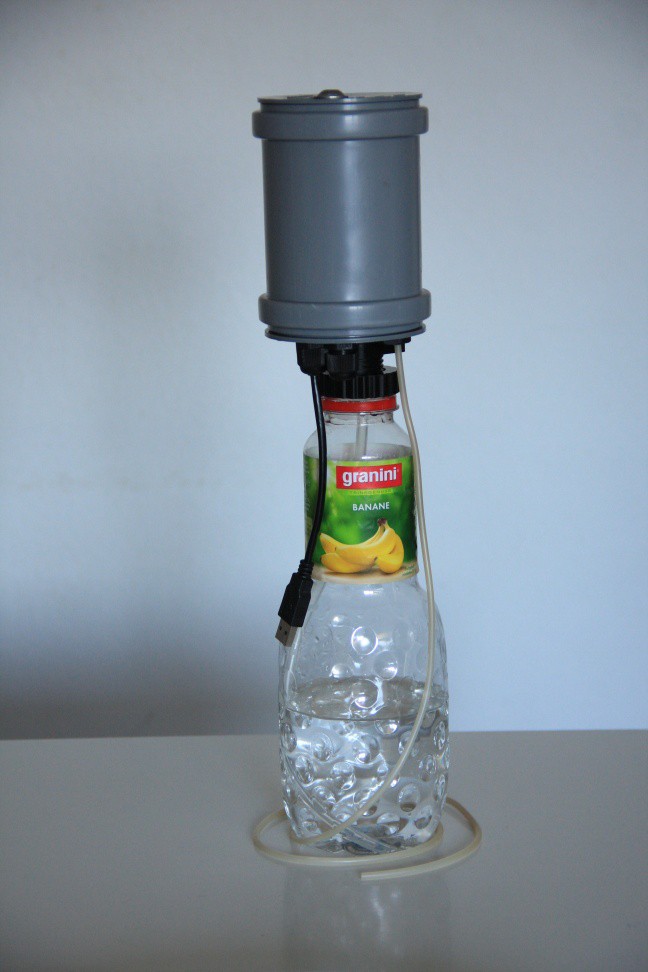
You do want to see the Granini bottle thingy, don't you?
![]()
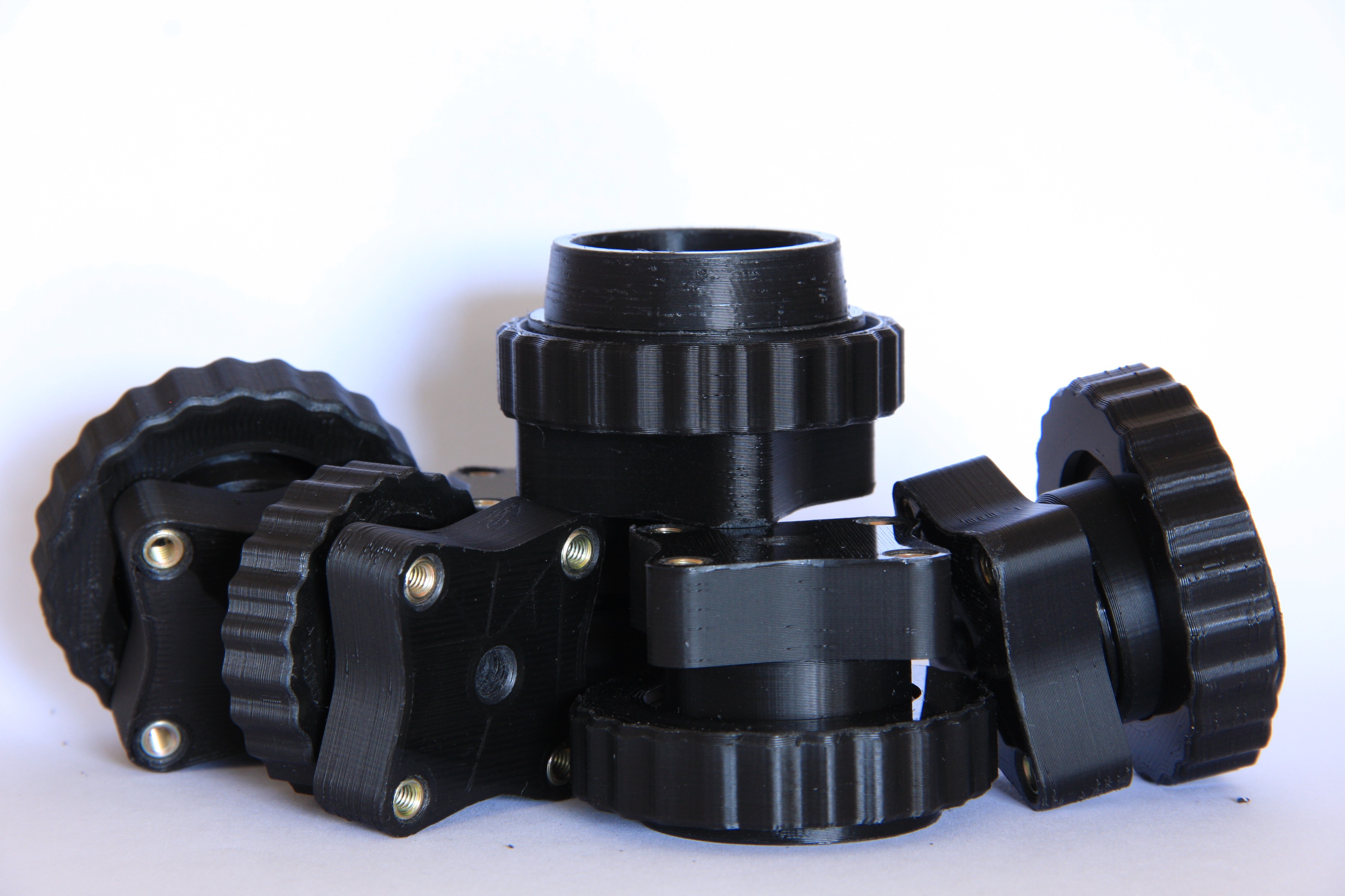
To attach the pump head to a vessel, a few 3D printed parts according to the neck finish definitions are needed.
![]()
The cool thing about 48/41 is that it's a 3-start thread with a large pitch, so twisting the swivel nut by 90-120° undoes the connection and allows easy removal of the pump head for refilling.
We had a little bit of a discussion regarding funnels and how to refill the reservoirs. In my opinion the 48/41 adapter in conjunction with exchangable 5 L bottles is a great trade-off since it starts making sense to just swap the bottle for refilling.
![]()
There is a suction line running down the center of the adapter which needs a little weight at the end but that's about all to get the water out since the peristaltic pump is self-priming. One of the main features of the adapter geometry is that when tipped over there's hardly any spilling and leakage.
A detailled explanation on how to create the threads is given here:
https://hackaday.io/page/5252-generating-nice-threads-in-openscad
The design files can be found on github:
https://github.com/MisterHW/IoP-satellite/tree/master/OpenSCAD%20bottle%20threads
First contact with Reality
We never fully deployed the concept despite a couple of parts that were built and iterated to clean up minor defects since we realized that stuffing the electronics in the head would be fine for a single plant one would like to leave out in the wild, but not so much for a more diverse growing setup where one or two reservoirs are to serve 20-30 plants. Additionally the bulky head stops making sense below 3 L now that the electronics is stripped as well. It may have its place, especially when implemented as a cheap spare reservoir that connects to intermediate tubing before routing out to the plants. This would be ideal for setups that have to be readied for longer vacations.
IoP water distribution
mechanical concepts for cost-effective, reliable automated watering for the Internet of Plants