I've spent some more time testing and have implemented a calibration step to the firmware that makes the ADC cell voltage measurements accurate to within about +-20mV. It is currently in the bug fixes branch on github. I'm going to spend some more time testing before I push to master.
Once you flash this firmware, you will need to run the calibration. It gets saved into one time programmable memory, so you will only have to do it once.
Hook up a DC power supply set to 3V-4V to the balance connection cells 1-4 and to the positive of the XT60 connector. Measure the input voltage with a multimeter, then in the LiPow command line, run "cal" followed by the voltage input in mV. It is a float and my meter is 5 digit so I've been entering something like "3849.3". It will take that input voltage and calculate the ADC scalars to compensate for the 1% resistor voltage dividers. You can check the output by running the "stats" command and checking that the voltages all are close to your input voltage. If you are happy with the calibration, you can save it to one time programmable flash with the "write_otp" command. You can run that command up to ~30 times and it will always use the latest saved calibration. You should only need to do it once though if you get a good calibration the first time. You can reflash the firmware without erasing the calibration once it is in the one time programmable memory.
I have spent more time testing and fixing bugs today. It can now push 60W of power into a 4s pack. I've also added a case to handle non USB PD chargers. That is limited to 5V 500mA.
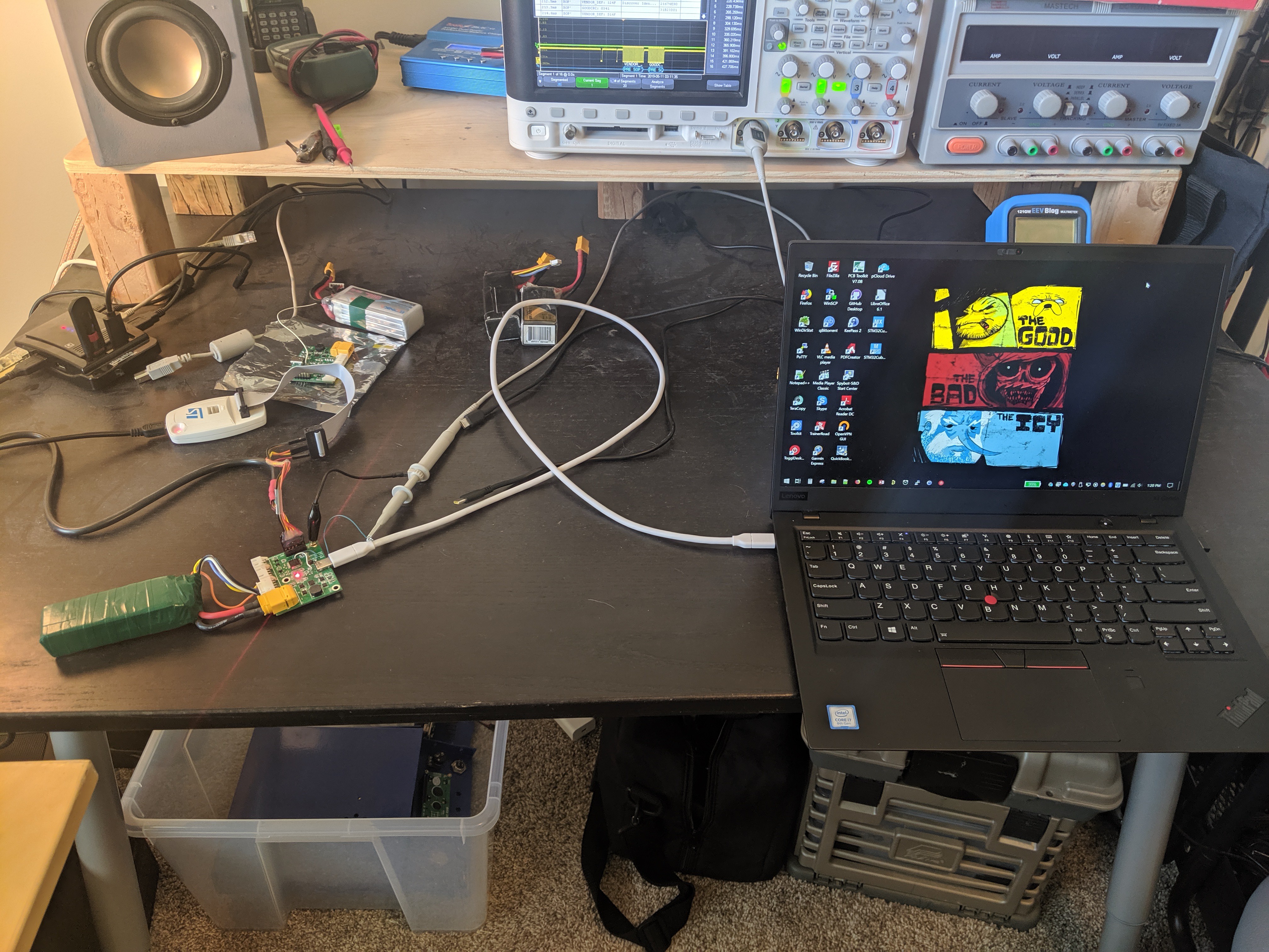
For fun, I tried charging off of my Thinkpad. It transmits a capability of 5V 3A and works flawlessly! I envision people carrying Lipow out in the field combined with a large USB PD power pack to charge batteries on the go.
I have completed a firmware MVP today. All features are functional. Battery cell number detection, cell voltage readings, balancing, USB PD discovery, auto selection of PD voltage for highest efficiency, auto calculation and setting of max charge voltage, and a basic command line interface for debugging.
In other news, I have placed the first order of production boards. They are Rev 3.0 and I'm calling this run a beta. They will go up for sale on Tindie. I plan on creating a machined aluminum case that will also serve as the heatsink. I will eventually put it up for sale as a finished product.
I have finally got the ST USB PD middleware basics working on the STM32G0. It reads in the capabilities from the source supply and can request the supply to change it's power profile. I still need to implement algorithm to a select power profile from source based on connected battery type to provide highest efficiency for the bq25703a regulator.
I have been working the last couple of weeks trying to get the USB PD Middleware from ST up and running but have not been having much success. Once I get this working, I can do some more testing and order beta units. Does anyone have advice on getting this running?
I finally got some time to work on this project again. Picked up where I left off and got 2s and 3s charging tested. It is now automatically charging and balancing 2s, 3s, and 4s batteries!
I set my bench supply to 20V and was able to get it to charge a 4s battery at 45W! It was also balancing and the temperature of the MCU did rise to 44C at room temperature. So heat may be an issue in the future.
 Alex Klimaj