 Mike Szczys
Setting Up the Toolchain
You will need a PIC programmer to write your own HEX files onto the badge. PICkit 3 and PICkit 4 have both been tested to work as programmers via the pin header on the badge.
The BASIC badge is based around a PIC32MX370F512H. Software is compiled using MPLABX, XC32 compiler, and legacy peripheral libraries from Microchip.
- Download three packages:
- Navigate to the Downloads" tab at the bottom of the Microchip Compilers page.
- Download
MPLAB® XC32/32++ Compiler v2.10for your operating system - Download
PIC32 Legacy Peripheral Librariesfor your operating system - Navigate to the "Downloads" tab part way down the screen at the Microchip MPLAB X IDE page.
- Install the packages:
- Install the XC32 compiler first
- Install the peripheral libraries next. IMPORTANT: You must specify the same directory as the XC32 compiler. This will likely not be the default option during install. For Linux installation this director was:
/opt/microchip/xc32/v2.10/ - Install MPLABX IDE
- Open the MPLABX project from this repository
- A PIC programmer like the PICKIT3 is required to program your badge
- On the PIC programmer, pins 1-5 correspond to RES, V+, GND, B0, and B1 on the badge
(If your programmer isn't recognized in Ubuntu 18.04 see troubleshooting below)
Testing Your Toolchain Installation
To test that the tools are properly installed before Supercon, clone the badge firmware repository on Github. Open the project, plug in your PICkit, and click "Make and Program Device"
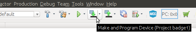
If all goes well, everything will work up to the point PICkit tries to communicate with a badge that's not there yet, at which time you'll see an error message like this:
Target device was not found (could not detect target voltage VDD).
You must connect to a target device to use PICkit 3.
Congratulations! You are ready to hit the ground running. Once you pick up your badge and connect it to your PICkit, the firmware upload should succeed.
User Examples for C Programming
The stock firmware includes an example program that has both a menu entry, and many of the commands that will commonly be needed to write your own C code.
- Selecting user program will run
void user_program_init(void)first.- This is where you should do all of your program setup. This is a good function to call from your program when you want it to start over again.
- After the init function is called,
void user_program_loop(void)will be called- This is where the main functionality of your program should be stored.
- If this function returns, it will immediately be called again.
- millis() is a 32-bit upcounting millisecond timer. Non-blocking delays are a matter of setting a variable as millis()+1000 and then polling millis() until it is larger than this variable.
Advanced
- The screen defaults to scanning a 40x20 character array (screen will automatically update when array data changes). For direct control of the screen:
enable_display_scanning(0);//Turns off auto screen scanning, value of 1 turns back on- view disp.h for screen manipulation functions to use in manual mode
- When directly controlling the screen, you will want to perform a screen refresh after badge wakes up from sleep
- There is function pointer in hw.h that will call your screen refresh function on wake. Here is the example for setting which function will be executed (do this in the initialization function of your program):
start_after_wake = &you_refresh_function;
Troubleshooting
Upon updating to Ubuntu 18.04 it seems that Microchip's udev rules for PICkit programmers have been broken by the new systemd configuration. Here's how to fix:
(These instructions found at: https://www.microchip.com/forums/FindPost/1071004)
$ sudo systemctl edit systemd-udevd
An editor will open to create a so called override.conf file.
In the empty override file, copy and paste this two lines:
[Service]
IPAddressAllow=localhost
Enter Ctrl-O to save, then Ctrl-X to exit.
$ sudo reboot
Compiler error on fundamental C types, like 'void':
error: variable has incomplete type 'void'
error: expected ';' after top level declarator
Recently Microchip upgraded their compilers to default to C99 standards, but older C code (like the legacy libraries used by the badge) do not meet that standard. You'll need to go into Project Properties and, under compiler global options, change C standard to C90.
fatal error: peripheral/adc10.h: No such file or directory
This error means the PIC32 Legacy Peripheral Libraries were not successfully installed. Please review installation instructions above, especially the part about specifying XC32 compiler directory.
Discussions
Become a Hackaday.io Member
Create an account to leave a comment. Already have an account? Log In.
MPLABX is less than ideal but it works pretty well with the default settings, you are just trading eclipse for netbeans for the most part. Microchip gets a lot of hate but they have a ton of cool MCUs its just ARM's heyday, I for one appreciate the Hackaday crew for breaking convention and trying something other than a SAMD21 or MEGA328p.
Are you sure? yes | no
For 64-bit Linux system you will need to install a few extra 32-bit libraries - see http://microchipdeveloper.com/install:mplabx-lin64
P.S. For 64-bit Debian you need to add "foreign" architecture i386 first:
dpkg --add-architecture i386
then update and install a few 32-bit libs:
aptitude update
aptitude install libc6:i386 libx11-6:i386 libxext6:i386 libstdc++6:i386 libexpat1:i386
Are you sure? yes | no
This is the reason why so many people are using Arduinos. I know the MPLABX IDE, but it is complicated to use and with a lot of settings, I'm sure most hobby users will give up or will need days until they can run their first program (just the config-bits settings is a nightmare).
But the PIC32 has even a protected 12 kB flash for a boot loader. And there is an Arduino compatible environment for the PIC32 (see chipKIT). I don't know if this supports the USB port as well for the boot loader, but then it would reduce your manual to 1. plugin the badge to the USB port, 2. start the Arduino IDE, 3. select chipKIT. No complicated software needed, and no extra programmer needed.
Are you sure? yes | no
Not everything should be Arduino-like ;)
Are you sure? yes | no
Getting Arduino IDE to program the badge would be a pretty cool hack all on its own. Are you saying you got it to work? I believe people should use whichever tool they can be most productive in, if that is Arduino IDE, go for it! In the final badge hack show and tell, what matters is the results.
I agree a beginner would be intimidated staring at the PIC config bits, I was one of them myself! Fortunately, for the purposes of Hackaday badge hacking, all of those bits have already been sorted out in the badge firmware repository on Github and most badge hackers won't need to deal with them.
For anyone who want to play with PIC and MPLAB outside of badge hacking, I found Microchip's MCC tool to be a great UI-based on-ramp to introduce those config bits in a less intimidating way. (MCC = MPLAB Code Configuratior, one of the downloadable plugins for MPLAB X IDE.)
Are you sure? yes | no
There is an Arduino like board with a PIC32MZ, so maybe it works with the PIC32MX of the badge as well:
https://chipkit.net
The user would then need to install just a plugin for the Arduino IDE:
https://chipkit.net/wiki/index.php?title=ChipKIT_core
I don't have a PIC32MX, so I can't test it.
Right, with the MPLABX example program for the badge, it gets a bit easier, and MCC is also nice. But there are still lots of details, e.g. don't forget to click the "generate" button for MCC, or don't forget to setup the not at all hidden menu "Production->Set Project Configuration->Customize->PICkit 3->Power" to the right setting etc. I'm sure there will get lots of questions, and annoyed users :-) MPLABX might be good for the power user, but would be best to have both: the MPLABX example project, but an Arduino environment pre-installed as well.
But looks like the badge doesn't have an USB connector anyway, that's a bummer. As someone wrote in the comments, with the 2016 badge you could just connect it with USB, it shows up as mass storage on your PC, and you could copy the new firmware to it. This badge is a step backwards with the need for an external programmer.
A way to save it without a layout change would be to use a serial port bootloader at the U3RX/U3TX pins. Then a user could use at least just a cheap USB serial port adapter, and if the protocol is Arduino compatible, still using the Arduino IDE. Might be tricky to reset it at the same time as the Arduino IDE wants to upload a program, but I've done that with some very cheap Nano boards, it is doable.
Are you sure? yes | no