daniel.bryand
-
Startup Weekend
09/09/2015 at 02:22 • 0 commentsIt has been a long time since my last update on this project, and many things have happened. After not working on this for awhile because of work and other things, my friend told me about a Startup Weekend Hackathon at UMass Dartmouth. I pitched the Infinity Dice idea, and was able to build a team around it. That weekend, we build a working prototype using a mish-mash of parts and a Taz4 3D printer (my first time using one, it didn't come out the best...)
![]()
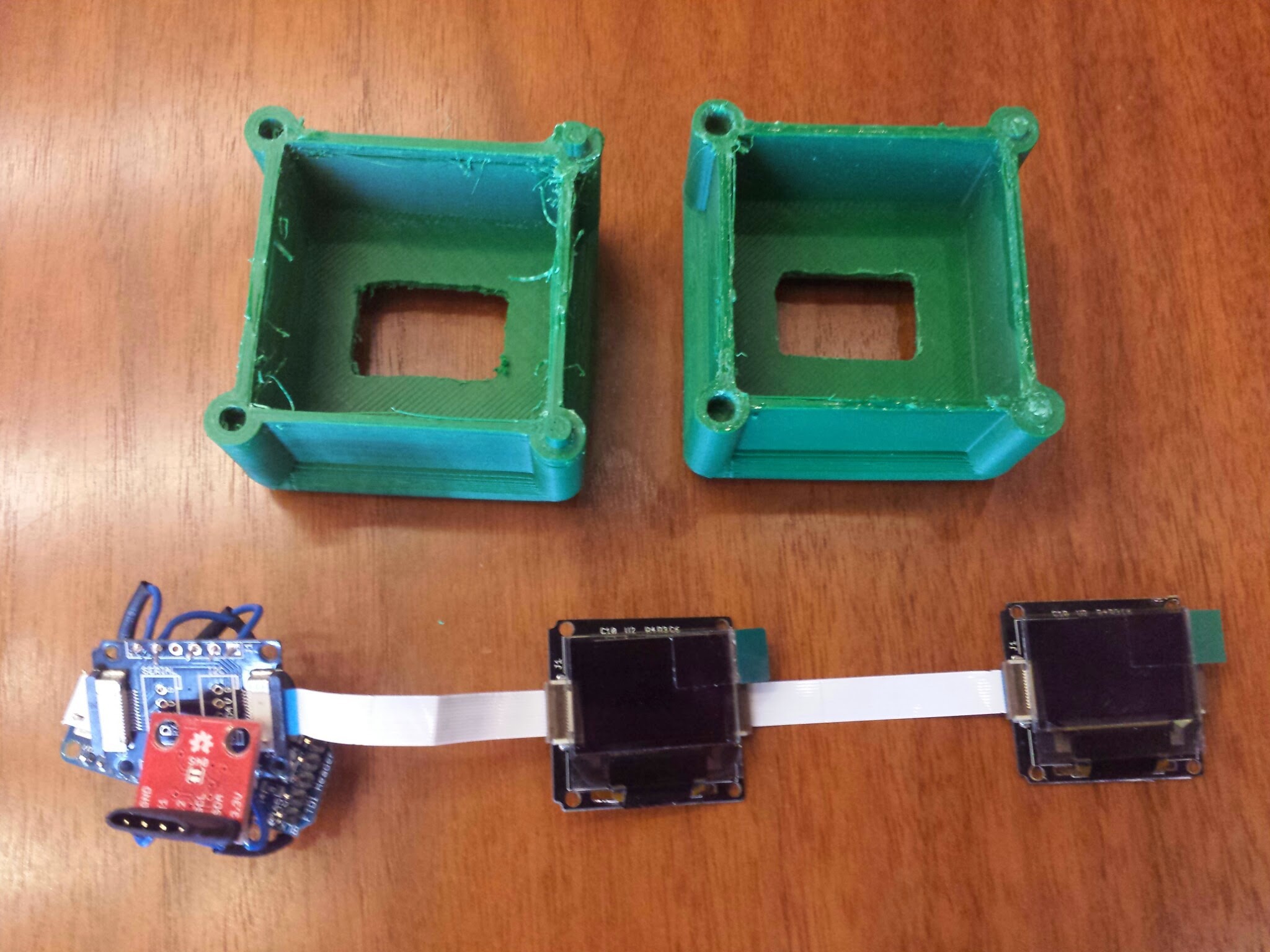
The components in this prototype were an Arduino trinket (I think), a Sparkfun accelerometer breakout board, a lipo battery, and two Xadow OLED screens. These were connected to the trinket through an Xadow breakout board. The programming was simple, when the accelerometer registered any change, a number from 1-20 would be displayed on both the screens.
Because of time constraints, both screens were connected via I2C serial, but they both had the same address, so everything was duplicated. Also, we could only get two screens, a bit short of the 6 that are going to be on the final version.
![]()
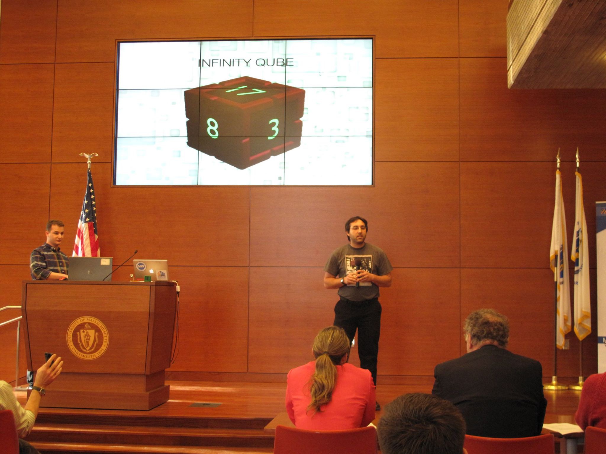
We presented to the judges with the working model in hand and a slightly different name "Infinity Qube". The other part of the team did some market research and quizzed students around the campus. I think we had a very solid pitch, and I guess they did also... we won first place!
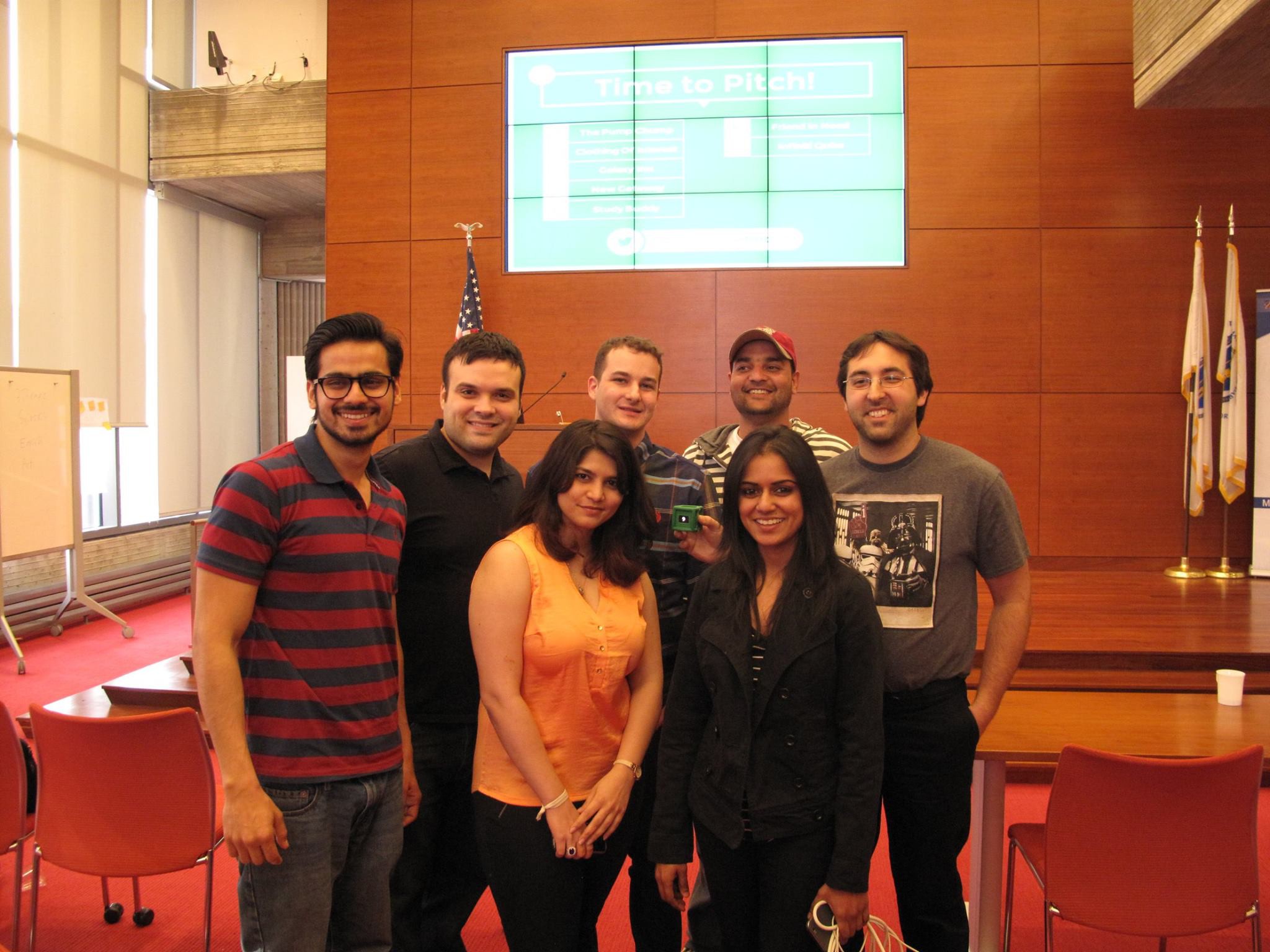
![Our team]()
Since that weekend, our team has changed a bit, but we are now working on bringing this idea to market! We are right now in bootstrap mode, part time, working around our other jobs. It is slow going, but progress is being made.
I will be updating this project page more often from now on, as well as some more in-depth updates on my website, mooseinspace.com. You can also check out our Infinity Qube page for any updates like events were going to be at. I am still doing all the website design myself, so it may be rough around the edges, but it'll get better as time goes on.
-
Design and Video
08/21/2014 at 05:01 • 0 commentsI have finally gotten around to making a simple design document and introduction video (kinda procrastinated on those...).
![]()
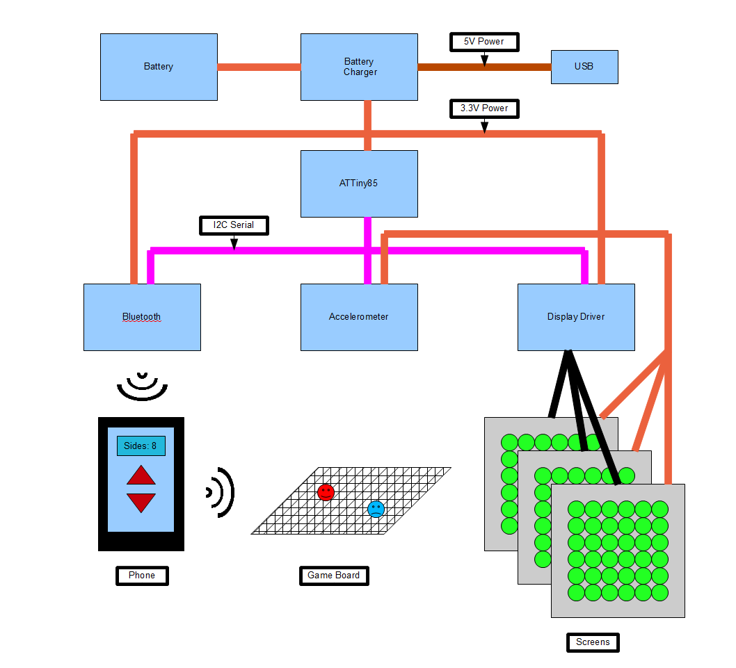
Here is the basic design of the infinity dice. It has the ATTiny at the center of the design with the Bluetooth, accelerometer, and display drivers all attached through a I2C bus in purple. The Bluetooth module that I have does not have an I2C serial communication feature, so this will have to be solved with either a different module or a I2C to SPI converter.
The red shows the power. Dark red is the USB charging power (5V), which will be regulated by the battery charge IC. The charging controller outputs the 3.3 volts from either the battery or the USB as needed to power all the other components.
The wireless section of this design shows a use of the Bluetooth feature. The phone can control the number of virtual sides on the dice, but it also acts as a bridge and brain for a smart board game. When the Infinity Dice is rolled, the number can be used to make decisions on the board game in parallel and possibly in secret from the players.
One last thing... I am still looking for some smaller screens. I would like to eventually make the dimensions of this dice comparable to a standard d6 dice. If you have any suggestions that can be easily controllable and give some good flexibility, post them in the comments!
Now, for the thing you have been waiting for... the video!
I am learning a lot with this project, and one of those things is making videos like this. I am learning about presentation (if you have any constructive comments, leave them here or on Youtube) and editing videos in Blender. There will be many more skills I will have to learn before the end of this project, so thank you for pushing me Hackaday!
-
Parts List
08/20/2014 at 00:00 • 0 commentsAs I'm working on this project (a lot slower than I'd like), I've started a list of the parts I am thinking of using and their prices. I'm looking at what it would take to order 1000 of these if it can git far enough. It might be a bit un-ordered right now, but it will eventually make it to the official BOM list on this site (that's what I've used so far).
The list is here: Bill Of Materials
-
Working Display
07/14/2014 at 20:08 • 0 comments![]() I found some time to play with the 8x8 LED display and control backpack I got in last week. At this point in the project, I am just going to look at each component individually and figure out how to use them.
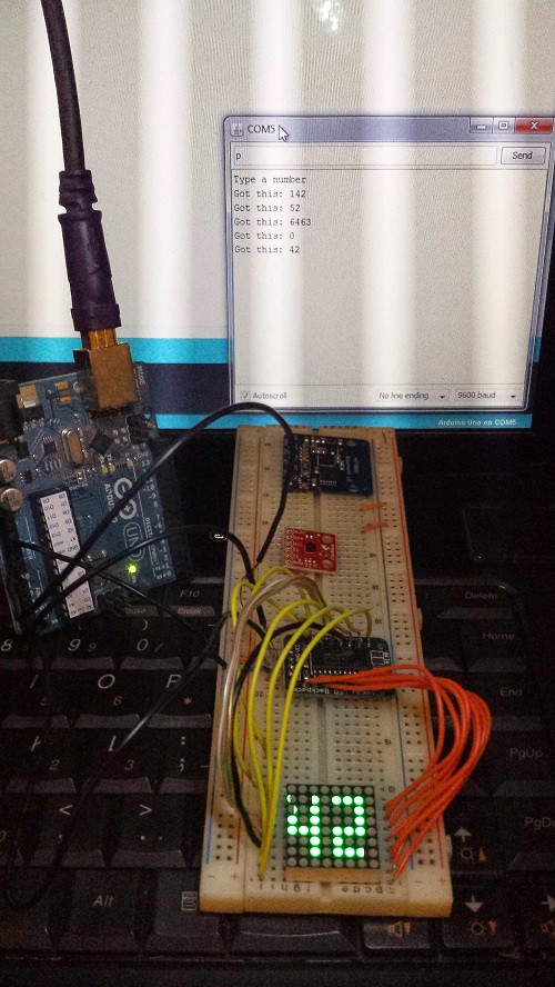
I found some time to play with the 8x8 LED display and control backpack I got in last week. At this point in the project, I am just going to look at each component individually and figure out how to use them.For this micro-project, I used the Arduino Uno, 0.8" 8x8 LED matrix, HT16K33 LED driver, breadboard, and the Arduino development IDE. I pretty much followed the tutorial on Adafruit to get started, except where it says to solder the matrix pins into the backpack, I wired it up.
Using the graphics libraries provided was quick and easy. I had graphics and text scrolling on the display in no time, and this may be useful depending on where the project goes. This is where I had to modify some things.
The built in font characters are 5x7 pixels in size, and I would like to fit at least 2 characters on the display at once (for now, number only). I created a new number font and layout method for the numbers. All the numbers are now 3x6 pixels in size, except for the 1, which is 1x6. I was hoping to fit 3 characters on the screen if 1 was the first digit, but I forgot I'd need 9 pixels across with spaces between the numbers.
The serial over USB was used to control the numbers being displayed. The Arduino has to check to see if a number was typed, figure out which number it was, and display that number. I will put the code up for this project on github soon!
Now that I am a little familiar with using this display and controller, I want to dig a bit deeper. One thing is I would like to use a smaller microcontroller, like the ATtiny85 (which I did receive, by the way). These have a smaller program memory, 8Kb, and the code I was using compiled to a little over 6Kb. With all the other devices, I might have to use only the parts from the libraries I need to get the bare bones working.
Also, I believe that this LED controller works well with 7 or 8 segment displays. I have a small red bubble display that I will be attempting to use as well. I can see how the memory on the LED controller is being manipulated by the graphics libraries, so I might be able to use this to extend to many separate displays as well.
Next I will be trying out the accelerometer and Bluetooth boards and attempting to tie them all together. I will also draw out some of my rough layout ideas on how to connect all these displays into a cube shape.
-
Components Arriving
07/09/2014 at 13:29 • 0 commentsI've been a bit busy lately with work and other things, but I did finally get around to ordering some parts I need to start experimenting.
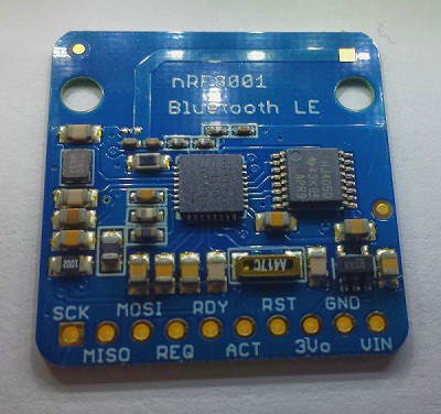
The first ones that came in was my Adafruit order. I saw that they had the nRF8001 low power Bluetooth chip on a breakout board, perfect for prototyping!
![]()
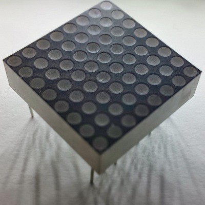
I was also looking at their displays and saw something intriguing, a nice 8x8 led matrix that is 0.8" square. It is a bit thick, but with 6 of these, a die of about 1.2" cubed could be made with nice dynamic displays. Its a bit bigger than I'd like, but its not bad for a first try. (If anyone knows of a smaller display, please tell me in the comments!). I also ordered the 7 segment red bubble display from Sparkfun because its smaller.
![]()
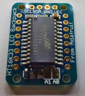
Along with that led matrix came a controller backpack. On it is a HT16k33 I2C led matrix driver. this chip can actually drive a 16x8 matrix, so a 6 sided die would need 3 of these driver, or if I use 8 segment displays, only need 1 driver (maybe). I'll have to see if it comes in a smaller package as well.
![]()
Hopefully the rest of the components come in today and I find some time start playing with them. I'll keep you updated!
Infinity Dice
You don't have to tap a screen or press a button for your electronic dice fix, roll one of these and get the results anywhere!
 I found some time to play with the 8x8 LED display and control backpack I got in last week. At this point in the project, I am just going to look at each component individually and figure out how to use them.