Craig Hissett
-
Digging
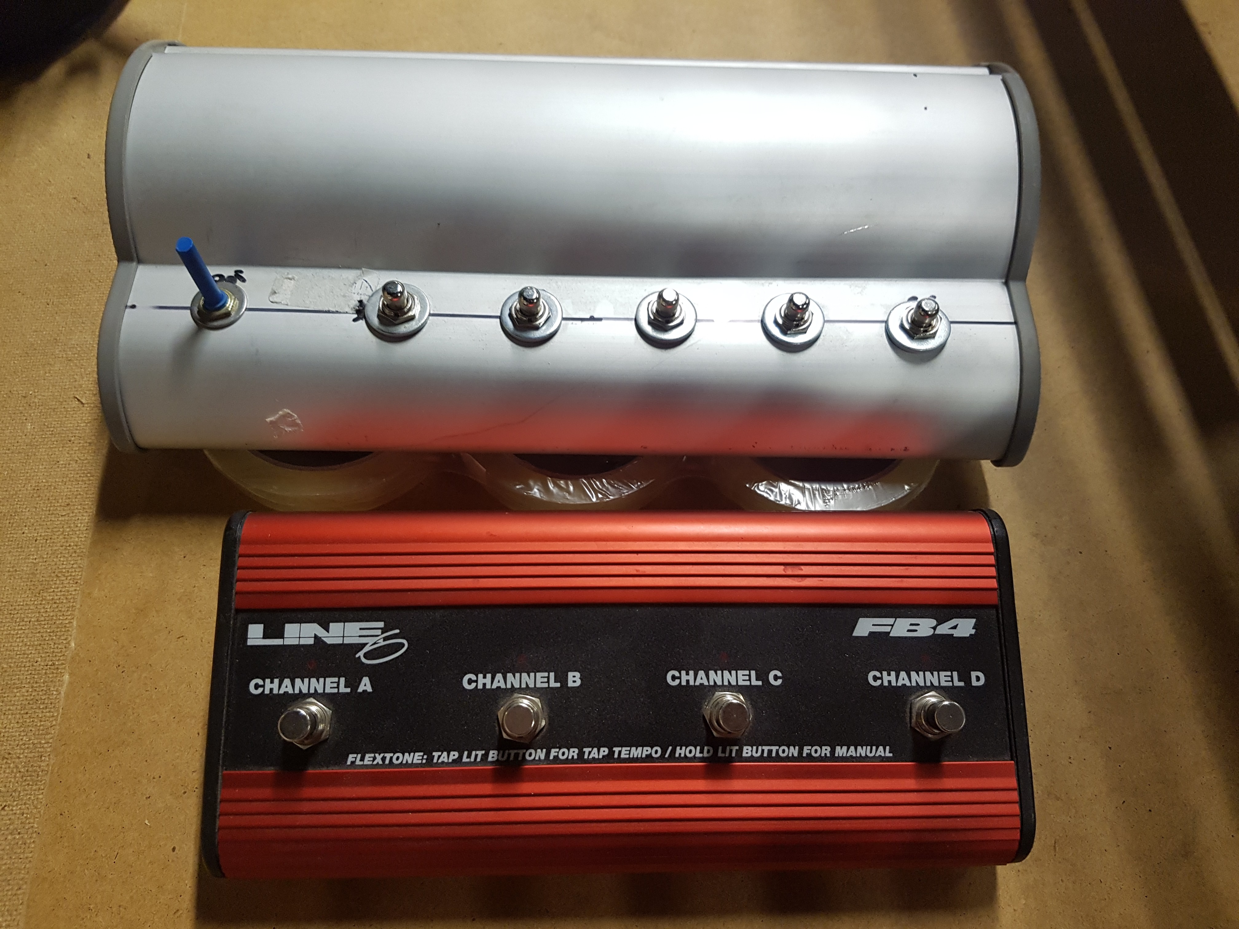
11/14/2018 at 00:02 • 0 commentsI managed to find an old footswitch I built many moons ago.
![]()
This grey monstrosity, pictured next to a Line 6 FBV footswitch, will be ideal to modify into my input device.
I might even squeeze the Tinkerboard inside, plus it could be modified to have a slot for the interface to fit into.
-
Collecting Parts
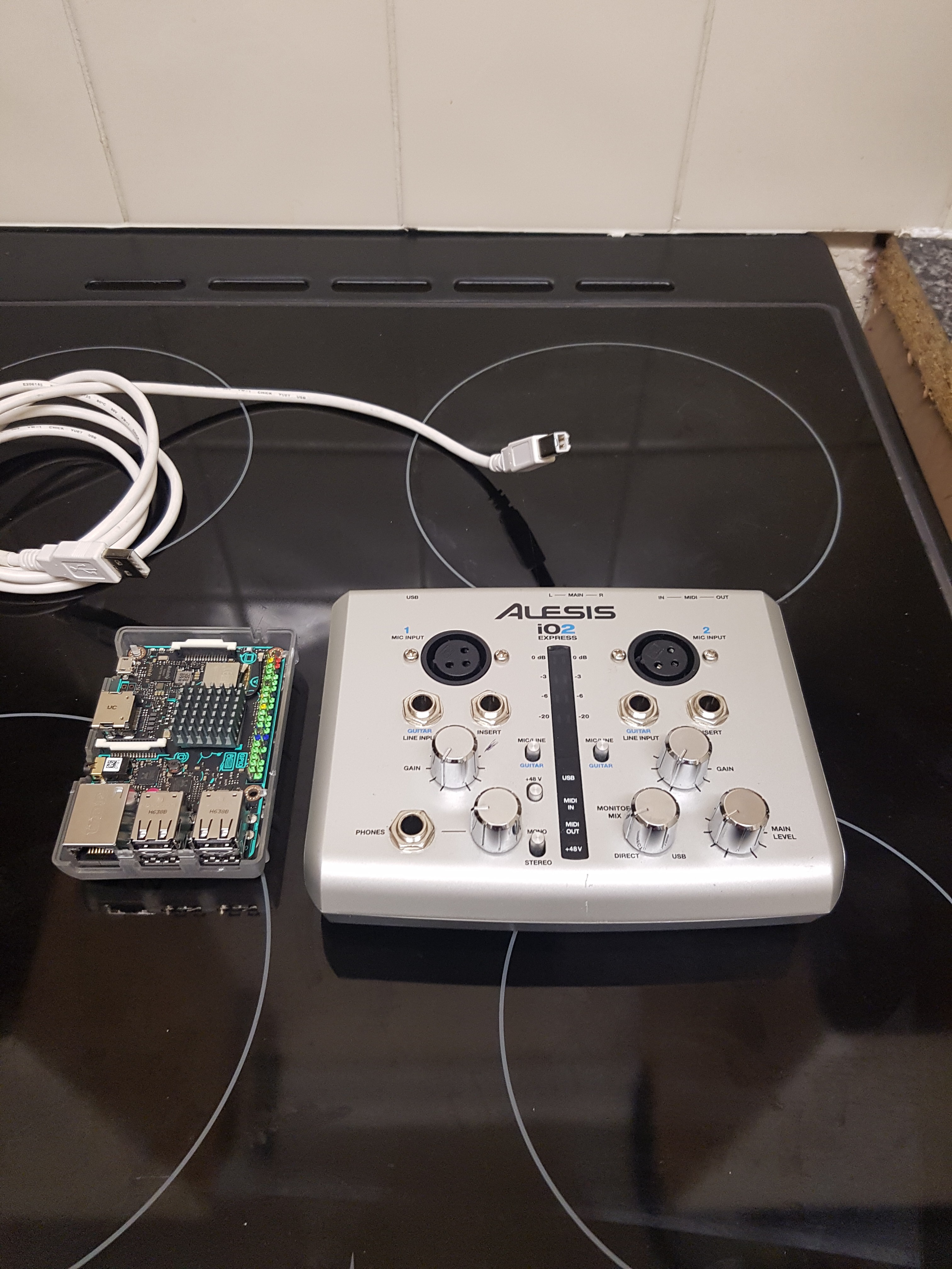
11/08/2018 at 00:26 • 0 commentsTinkerboard and the Alesis io2:
![]()
I built a footswitch a few years ago to allow triggering keyboard shortcuts on my PC while in the studio recording; I plan to dig it out and remove the switches and use them to rebuild an interface for this little beauty.
I would like to knock up two customs length USB cables in order to keep it all neat.
-
Software | Pure Data?
11/04/2018 at 07:27 • 0 commentsI've been looking for some options for software to run on the Tinkerboard.
Pure Data has cropped up in a few old examples and I think it is worth some investigation.
This example uses PD on a Raspberry Pi, controlled via TouchOSC app on a phone:
http://www.instructables.com/id/Pure-Pi-Control-custom-stompbox-effects-on-a-Raspb
And this one is a project that uses PD with an Arduino (running Firmata) as an input reading Stompbox switches and a DIY expression pedal:
https://guitarextended.wordpress.com/2013/01/31/raspberry-pi-multi-effects-overview-of-the-setup/
I would love to take elements from both of these to come up with a setup that can operate like the second link, with a TouchOSC interface for more complex parameter editing.
-
Testing Setup
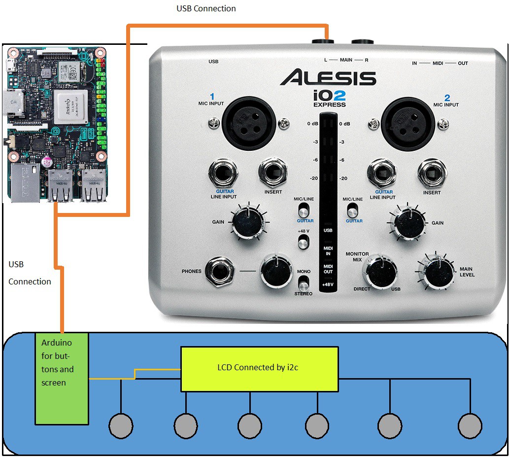
11/03/2018 at 01:45 • 0 commentsOver the next week I'm going to aim to assemble a test board to start playing around with using a linux SBC to process audio, and using an Arduino to display updates on a display and pass input parameters from stompbox switches.
![]()
While in future iterations I'd like to incorporate the XLR and jack inputs and outputs this testing setup will use an external interface mounted to the test board.
The Alesis io2 interface is perfect for this setup; it's plug and play, has XLR inputs and line inputs, has insert points for adding more effects if necessary and a headphone out. The added bonus is I have one spare :)
For the SBC I have opted for an Asus Tinkerboard. It's more powerful specs will help keep latency to a minimum.
I will look for various examples of software to try out; I'm looking for something I can run headless and preferably use Python to manipulate parameters (this will make using the arduino a lot easier).
Another nice feature would be to connect to the Tinker board to use a web interface for a more detailed user interface.
While a test rig I'd love to make this device look the part. I'd like to mount everything to a base plate and place a cover over the Tinkerboard and arduino, make cutouts for the switches, the lcd screen and also a small opening for the interface USB cable to pass through. Adding some panelmount sockets for ethernet and the two spare USB ports would be great for expandability and connecting for programming and updating.
-
Idea 3 | Potential Diagrams
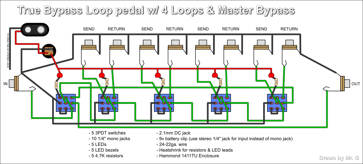
11/01/2018 at 01:01 • 0 commentsHere's a quickly google sketch to show how Idea 3 could work.
The send/return loops would got to pins on the Arduinos, rather than jack sockets.
![]()
-
Initial Concept | Further thoughts
10/31/2018 at 14:04 • 0 commentsI've had a few ideas to mull over the concept of this device and have thought of a couple of ways to tackle this, all with their pros and cons.
I've roughly rounded them into 3 general Idea outlines:
Idea One
First thought is to use an Arduino Mega as a 'master' device, handling an LCD display and reading all onboard knobs and controls.
Comms between the individual effect devices would be either Serial (using the Mega's 4 Serials plus software serials if required) or i2c, depending on what is faster.
On startup the Master could try to establish connection with each of the configured ports (or scan the i2c bus for devices) to determine what devices are there and what to map controls to.
The Master then reads all control input and sends commands to the appropriate device.
I could write a library for the slave devices to ensure they can all interpret the data sent from the master and make use of it; the packet could contain data such as [ON/OFF, Control1, Control2,Control3] , which the slave device could then use to manipulate the audio data.
Idea 2
A Pi master device, with an Arduino Mega handling all input.
The Pi could then run VSTs to manipulate the audio signal, with Arduino connected via USB/Serial to then control the VST settings.
Idea 3
No traditional master device to tie together individual parts.
Perfboard soldered up with sockets to plug Arduinos in, with a 'true bypass switch' (3PDT 9 pin switch) to control whether arduino included in signal path, with all knobs and input controls hardwired to the arduino socket. An extra arduino could be included as a slave to control an LCD.
-
Initial Concept
10/24/2018 at 19:59 • 0 commentsI've got a rough idea of how this could work:
XLR in would feed into some kind of backplane with slots for inserts to be added.
A master Arduino would read button presses from the box (currently thinking of a long H hammond style enclosure at the minute, or a custom wedge shaped box) which would then control which insert points affect the signal, before heading to the XLR output. Id like to have a dry output as well, for options.
The inserts would either be Pi Zero boards or Arduino boards pre-coded to carry out a particular signal processing task.
I'd also like to have one of the inserts for a volume pedal, and one or two jack sockets for expression pedals to be added. These could be read like potentiometers by the inserts.
There could be a lot more efficient ways of doing this, such as true bypass switches, but the thought process is a fresh one ha ha.
Multi fx Stomp Box
I am looking to build a modular 'pedalboard in a box'. It's so crazy it just might work...