 adria.junyent-ferre
The mechanical bits
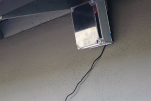
The mechanical arrangement is pretty simple. I drilled three holes on the lid of a junction box, 3.5mm x 2 + a hole of 14 mm diameter. A 3d-printed bracket holds the camera in place using M3 screws. The part prints in some 10 minutes and is good for most camera modules. A different bracked it used to hold the Raspberry Pi Zero W inside the junction box. This part prints in 10 minutes as well. Two more M3 screws are needed there. I drilled an additional hole on the junction box to hold the tripod in place. One of the knockouts was pierced in order to fit the USB cable through the hole.
The software side
The Raspberry Pi runs standard Raspbian. I set it to boot to the terminal using raspi-config and enabled the camera and the SSH service through the applications as well.
You could make the RPi connect to your wifi network but I thought it would be tedious to have to use a keyboard and a screen to log on to the RPi and change the password whenever I changed my router. Therefore, I chose to set the RPi as a wifi hotspot so that I can connect to it from a Laptop and dump the pictures or do whatever I please. The process to set up the system is surprisingly straightforward. You need to install hostapd and dnsmasq. The steps are described here:
https://www.raspberrypi.org/documentation/configuration/wireless/access-point.md
Once I got the wifi setup properly, I was able to get rid of the screen and the keyboard and work on the software from my laptop through a SSH connection. The next step was to set up the camera software. I use fswebcam to capture the snapshots. Detailed step-by-step instructions can be found here:
https://www.raspberrypi.org/documentation/usage/webcams/
When I followed this procedure I faced a little problem: fswebcam complained that /dev/video0 didn't exist. This can be sorted out by loading the proper kernel module by running modprobe bcm2835-v4l2
Most camera modules don't have the ability to autofocus and one needs to adjust the focal length by twisting the lens. This process is tedious if one has to wait to see the snapshots from fswebcam. It is much better to watch a live videostream. This can be done using gstreamer, the best piece of software I discovered in 2017. I believe this is installed in Raspbian by default but one can install it by issuing apt-get install gstreamer1.0 at any time. The TCP video streaming server is started from the RPi by running:
raspivid -fps 26 -h 450 -w 600 -vf -n -t 0 -b 200000 -o - | gst-launch-1.0 -v fdsrc ! h264parse ! rtph264pay config-interval=1 pt=96 ! gdppay ! tcpserversink host=192.168.4.9 port=5000And from the laptop one can run the following command to watch the video:
gst-launch-1.0 -v tcpclientsrc host=192.168.4.9 port=5000 ! gdpdepay ! rtph264depay ! avdec_h264 ! autovideosink sync=falseIn my case, I made the mistake of pointing the camera upside down, this can be fixed from the client side by adding "! videoflip method=rotate-180" to the pipeline before autovideosink.
Once the camera is focused properly, one can stop the gstreamer on both the server and the client and set up fswebcam to capture the snapshots. At the moment I'm running this command by manually logging into the RPi but a script can be set up to run automatically on boot by adding the command to rc.local (https://www.raspberrypi.org/documentation/linux/usage/rc-local.md).
Notes about the power consumption of this device
I made a quick measurement of the power consumption of the Raspberry Pi and basically, it takes about 0.08 A when iddle (no streaming), about 0.17 A when running the video stream through wifi as described above and 0.02 A when on halt (after issuing a shutdown command leaving the USB cable connected). This is quite a modest consumption. From my rough estimates, you could easily run the video stream through wifi for about 2 hours by feeding the Raspberry Pi from a £1 USB powerbank (these can fit 0.25 A for about 2 hours). What a time...
Read more »
 J. Peterson
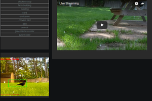
 Brenda Armour
 Eugene
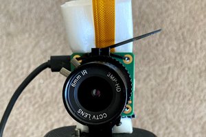
 Huan Truong
Adria,
I just wrote to WorstHorse. I do not know how people cooperate here. I am just getting started.
And I do not know how to CC comments and messages. It is a pain to copy things I can barely see.
His SDRs are mostly using USB for sharing the data with the data storage servers. But the chips on the SDRs (an analog radio tuner, and an amplifier/ADC/Usb interface) are readily available and have alternatives, that can be adapted for Pi Zero or ESP, Arduino and other processor boards.
Richard
----------------------------------------------
networked RTL-SDR server - a wifi-based RTL-SDR receiver to cover 1 to 500 MHz
WorstHorse:
If you work with adria.junyent-ferre and others who are trying to network sensors and devices, you might be able to rough out some conventions, and share what you have learned. I like her approach. You basically design your SDR as a "sensor", then prepare a data stream that can be shared with others. You might try setting up a nodejs data server somewhere on the network.
I suggest stick with IP networks to start, as you have done. But it seems ridiculous for you and hundreds of thousands of other developers to keep build the same software hooks just to write your datastream onto some other device.
I will try to find some framework to make it easier. But you and Adria could at least talk about the broader data sharing needs of sensor data streams.
Personally, I would like to run ten of your SDRs for several weeks to see what the data is telling me about correlations.
I have been looking for low cost ampliier boards and high sampling rate ADCs (Gsps+). Do you know how to order PCB's? I see them mentioned but do not know where to start. I can probably find and combine amplifier and ADC designs, if I don't have to assemble them myself. From what I hear, they are fairly inexpensive, and I would like to be able to give away some to people who are struggling just go get some data.
Is there any way I could get you to change the name of your project to read "Zero to 1 GHz"???
:)
Richard Collins, The Internet Foundation