Close
0%
0%

Magnetic Loop Antennas for QRP Amateur Radio

An ongoing exploration and experiment about the use of small magnetic loop antennas for QRP (low power) Amateur Radio.

Similar projects worth following

Living and operating from a "challenging" QTH does not mean that one cannot take part in Amateur Radio. In my case our garden is too small for huge towers and long wires and there is a hill right behind the house anyway. Instead of feeling discouraged I took this as a challenge to get QRV with minimum power, occupying minimal space and - last but not least - have the whole thing sitting indoors.

The antennas I am using are small magnetic loop antennas. Their main characteristic is the use of the magnetic component of the electromagnetic field for both transmission and reception. The widely used Yagi (TV aerial) antenna for example uses the electric field component.

On the transmitting and receiving side of things I am using a Yaesu FT818ND transceiver with maximum 6W power output. For my WSPR experiments a Raspberry Pi Zero provides 10mW.

DISCLAIMER: I take no responsibility for any damage or losses caused by the building and or operating of the antennas described here. Please be aware that even with only a few Watts transmit power the voltage at the tuning capacitor can reach several hundred Volts or even more with currents up to a few Amperes. I do not recommend this project to people with a cardiac pacemaker or ICD.

This is the basic antenna design:
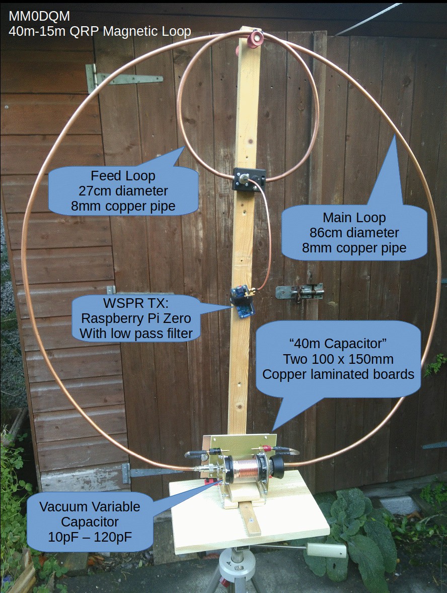
This configuration uses a Raspberry Pi Zero as WSPR transmitter for 20m and 40m. Thanks go to Jenny List and her Australia Project that inspired me to try a Pi Zero on a loop. Otherwise the FT818ND can be connected to the feed loop as well.

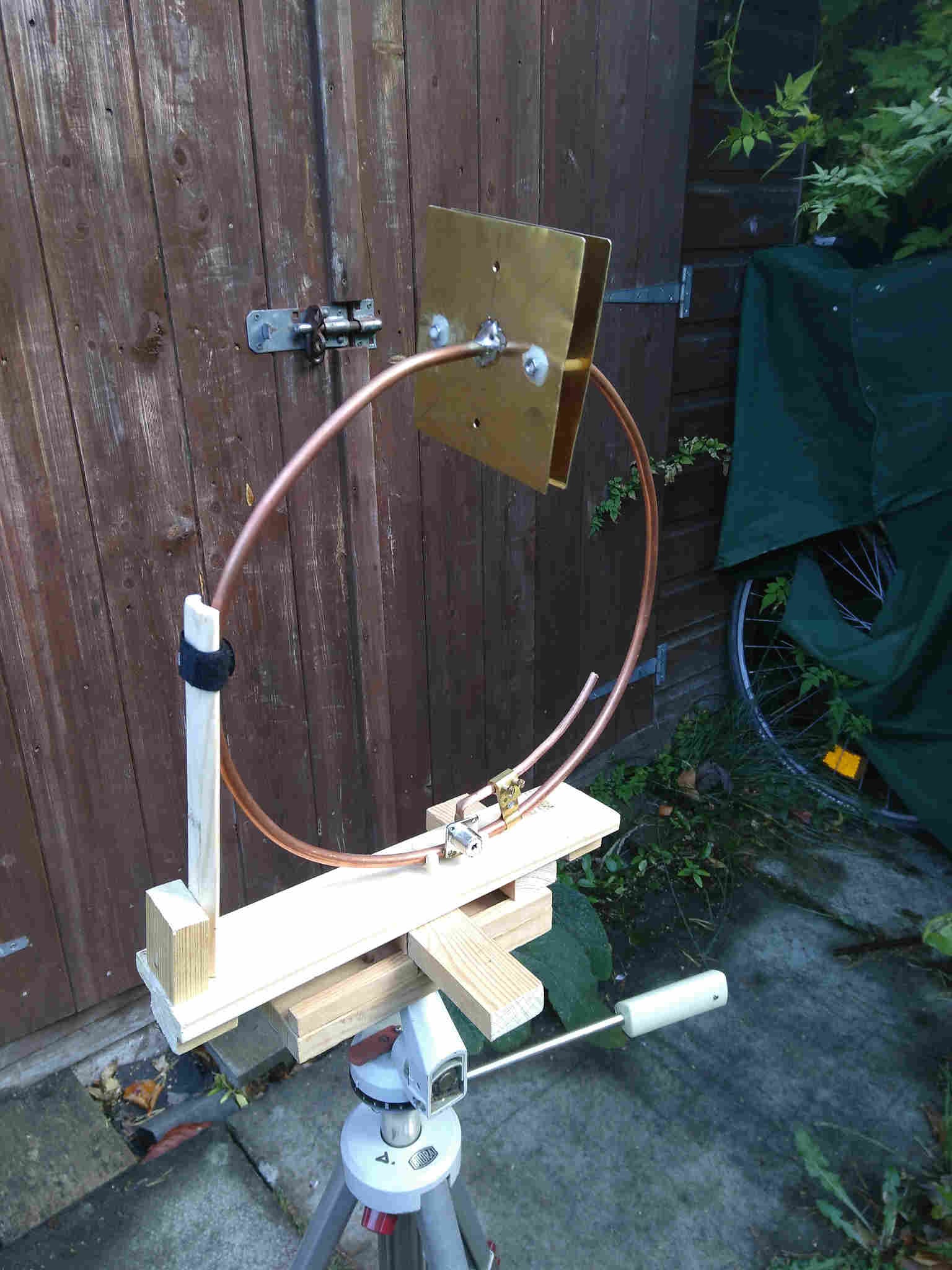
This one is it's smaller and slightly different sibling: Designed mainly for the 50 Mhz / 6m band. Two brass sheets act as air gap tuning capacitor.
  • 1 × 8mm diameter copper pipe Sold as "small bore" central heating pipe in DIY stores
  • 1 × 200 pF variable capacitor small variable capacitor for matching the feed to the loop.
  • 1 × 10pF - 120pF vacuum variable capacitor The expensive option for tuning the loop (unless you get it for a tenner at a junk sale like I did)
  • 1 × 2 section 250pF air gap variable capacitor Another (cheaper) option for tuning.
  • 2 × copper laminated sheets, 100mm x 150mm For the 40m add on capacitor

View all 7 components

  • Radio killed the Radio Star - or how to avoid crashing your PiZero

    Mark Dammer MM0DQM11/17/2018 at 10:19 0 comments

    There have been numerous reports about Raspberry Pis crashing when using the WsprryPi software. My Raspberry Pi Zero was no exception when feeding the magnetic loop antenna. These crashes usually happen right at the beginning of a transmit cycle and network connectivity is completely lost so the Pi needs a hard reset. Oddly on some days the system crashed all the time and on other days it worked like a charm. I found the source for these crashes thanks to someone on the WsprryPi issue tracker suggesting RFI (Radio Frequency Interference) as one possible cause for this problem:

    With the Pi mounted almost in the centre of the loop, the power cable that connects it to the powerbank was sometimes dangling too close (less  than 10cm) to the bottom of the loop and the capacitor. As this is the "hot" part of the loop with fairly high electric fields, RF was creeping in the lead leading to these crashes.

    Keeping the cable away from the loop solved the problem. And maybe it's not a bad idea to put a ferrite choke on the cable.

    72/73 for today, Mark

  • WSPR - The Big Jump: Over 1700Km with 10mW from my office

    Mark Dammer MM0DQM11/04/2018 at 09:32 0 comments

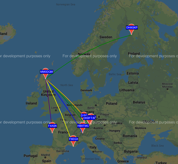
    Now it was time to test the PI-Zero as a WSPR beacon. Yes, a Raspberry PI can act as a transmitter (almost) without any additional hardware except an antenna. The RF signal is generated directly from the systems clock oscillators and it is available at a GPIO pin. The main problem is that this output signal is a square wave. This means loads of harmonics and other unwanted signals that a good radio amateur does not want to transmit. It would not only be bad conduct but violate spectrum regulations in most countries. Usually low pass filters are used to reduce these spurious emissions. In this case the very narrow frequency response of a magnetic loop antenna helps to further reduce unwanted transmissions.

    I am using a 7 pole Chebyshev low pass following the design used in Janny Lists "Australia Project".  An additional 100nF capacitor between the filter and the loop is needed to avoid a DC short circuit that may destroy the Raspberry Pi.

    The software on the Pi Zero that creates the time synchronized WSPR signal is called "Wsprry Pi" and can be found on Github.

    For the experiments the Pi Zero was powered from a Power Bank. I connected to it via SSH over a WiFi connection. The antenna was sitting in my office on the ground floor.

    Because the PiZero WSPR system does not receive I had to use my Icom IC-R10 scanner/receiver for tuning. For minimum sensitivity the R10s rubber duck antenna had been removed and the attenuator enabled. Because loop antennas have minimum field strength on the front/back axis it was not too difficult to find a spot where the scanner showed only a small S-Meter reading. Now it was possible to tune the loop for maximum output.

    The result was astonishing: Spots from Finland all the way down to the Mediterranean with just 10mW and an indoor loop antenna.

  • First Experiments with FT8

    Mark Dammer MM0DQM11/04/2018 at 09:07 0 comments

    This first experiments with FT8 this summer showed very encouraging results. I used the FT818ND with 5W output power to the loop. 30m turned out to be the best band for daytime activity. The antenna was not fully optimized at this point - the simple air gap variable capacitor was used for tuning.

    I was able to make successful contacts with Norway, Germany and France over a maximum distance of about 1500 Km.

    Once I had started using the vacuum variable capacitor for tuning I was up for the big surprise: Suddenly my CQs got picked up by stations thousands of kilometers away in both directions: The Ukraine to the East, Wyoming in the USA to the West and the Canary Islands to the South.

  • Feeding the Loop

    Mark Dammer MM0DQM11/03/2018 at 19:53 0 comments

    There are many ways to get the radio connected and matched to a magnetic loop antenna. Amongst all the army, delta, gamma, toroid and whatsoever feeds the simple inductive loop is widely used. Many sites state that a feed loop with a diameter of about 1/5 of the main loop will give the desired 50 Ohms match for the bands you want to cover. However having experimented with feed loops of different sizes, shapes and diameters in different environments I can say that there is no easy "one size fits all" matching method:

    In my experiments the core problem was not so much the loop itself, but the environment. The RF characteristics of a magnetic loop are very much influenced by conducting objects in the close vicinity (~2m) of the loop. This includes not only larger conducting objects like humans, cars, freezers and fridges, but in my case a bicycle parked nearby completely spoiled the SWR probably because the rims of the wheels acted like short circuited loops - no joke.

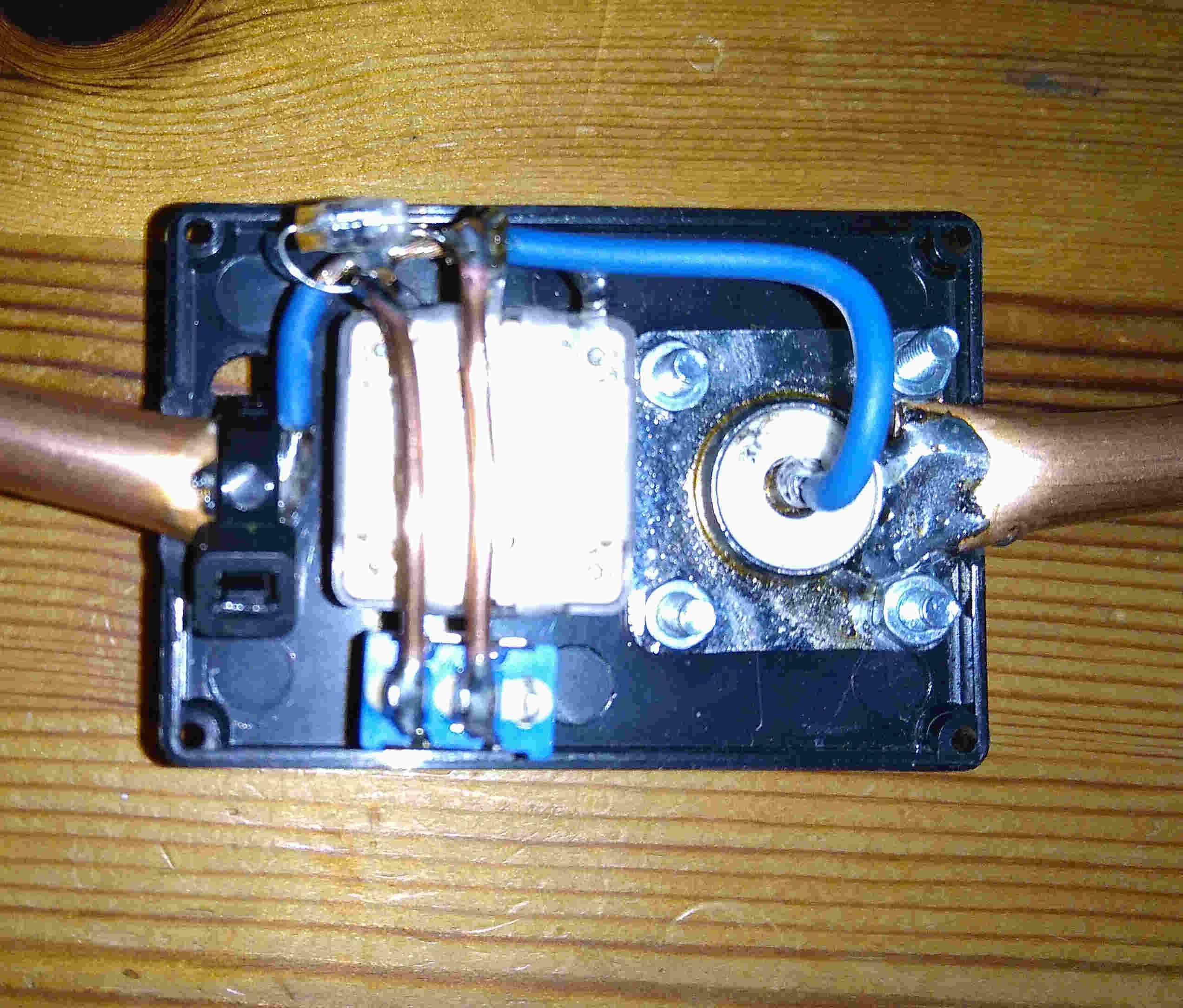
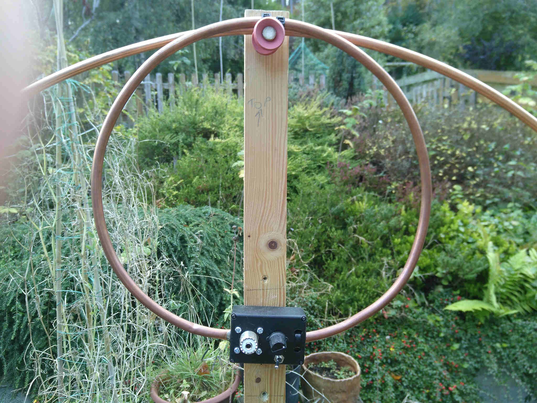
    Because I want to be able to match the loop even under difficult circumstances (indoor and almost always "problematic" objects nearby) I put an additional variable capacitor with max. 220pF in series with the feed loop. The little 100pF cap sits parallel to the variable and a switch allows to bridge the capacitors so that the feed loop is directly connected to the radio. With this setup I am able to get a good SWR close to 1:1 even in difficult situations.

    A close up of the main feed loop (Diameter 27cm):

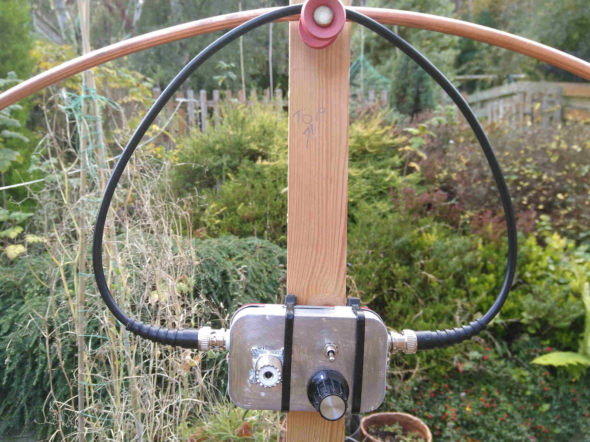
    One day I took the antenna for an outing to our T-Exchange makerspace meeting and only got noise and buzzing out of the transceiver. The main reason for this level of QRM was the LED lighting in the venue but the various computers etc. at the meeting added their part to this cacophony. As a consequence I developed a second feed system based on the Faraday Loop:

    The circuit is basically the same but this time in a shielding metal box. Simple RG58 cable with BNC connectors forms the loop. While the right BNC socket is the "hot" end of the loop where the core connects to the radio / matching capacitor and the cables shield to ground, only the core is connected to ground at the left "cold" socket and the shield is not connected (notice the insulated socket).

    I have seen discussions on the web that question the effectiveness of a Faraday Loop. I have to say that this shielded feed picks up less noise through electrical fields and capacitive coupling. The influence of magnetic noise sources can be reduced by turning the antenna until the noise reaches minimum.

    Although this feed improves reception in noisy locations, it comes at the cost of slightly reduced transmit performance. For this reason I have these two feed systems available - one for high performance and one for high QRM environments. In both cases the box containing the matching circuitry is held in place by a velcro strap that runs around the wooden boom. Changing the feed system is a matter of seconds.

  • Tuning the loop

    Mark Dammer MM0DQM10/27/2018 at 20:18 0 comments

    For optimum performance (High Q) the loop should have a low electrical resistance and the tuning capacitor low losses.

    Please be careful: Even with just a few Watts transmit power the tuning capacitor must be able to handle several hundred Volts and currents of a few Amperes.

    The cheap option:
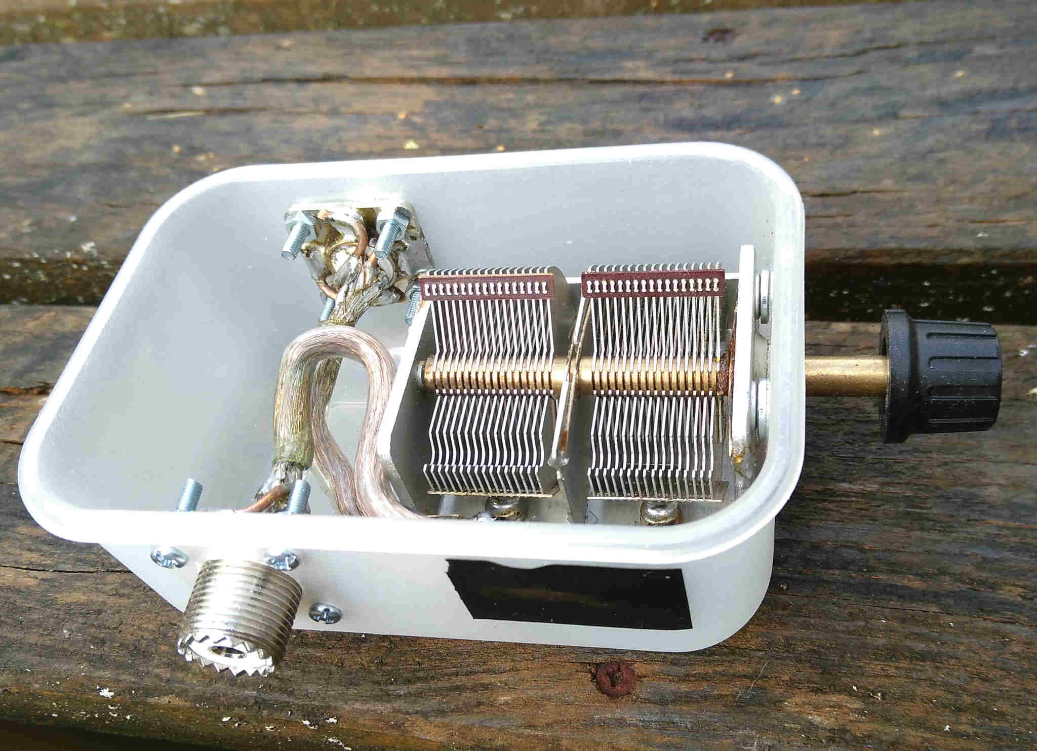
    Air gap tuning capacitor with both sections used in series to avoid the use of lossy sliding contacts.

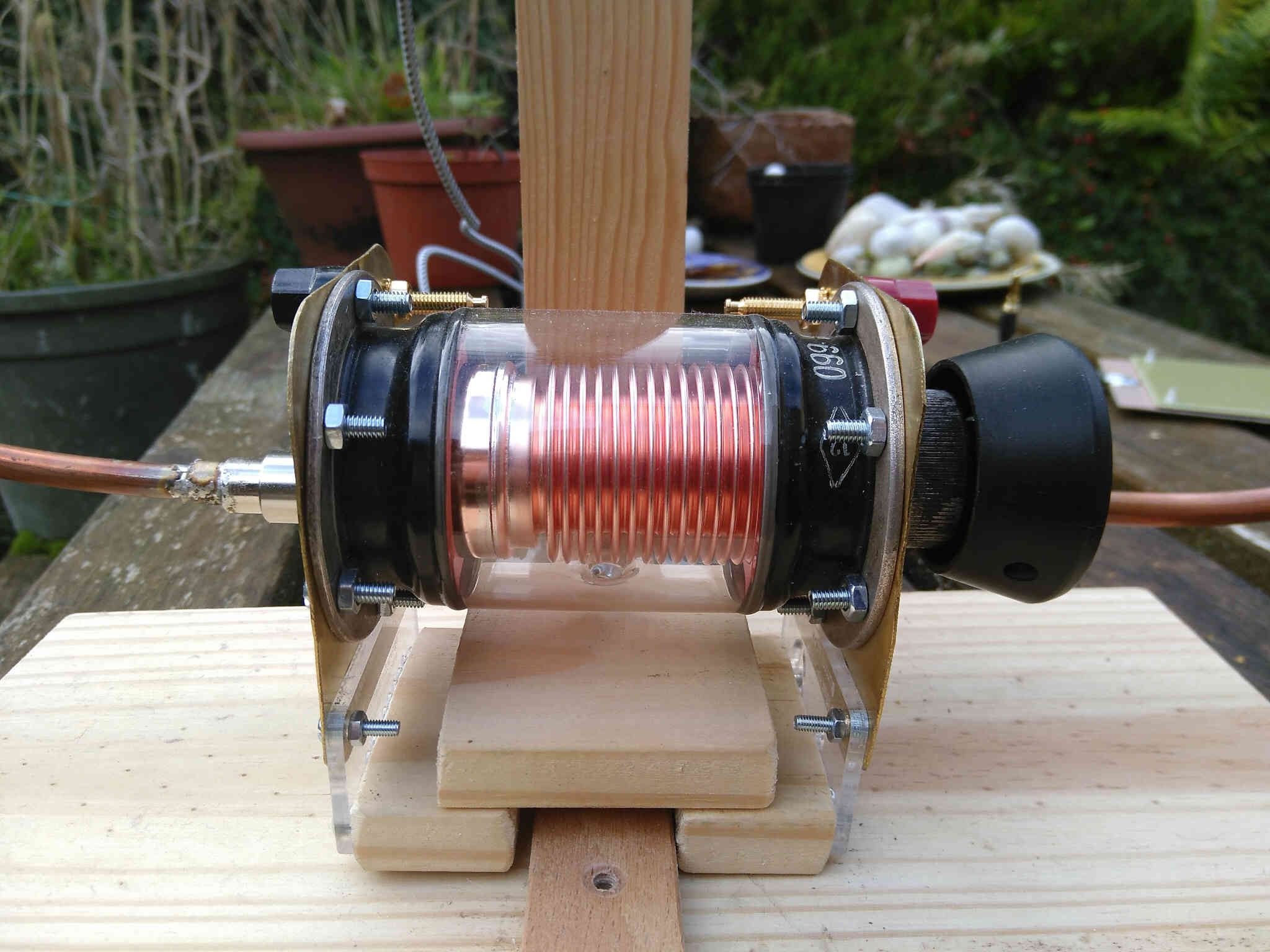
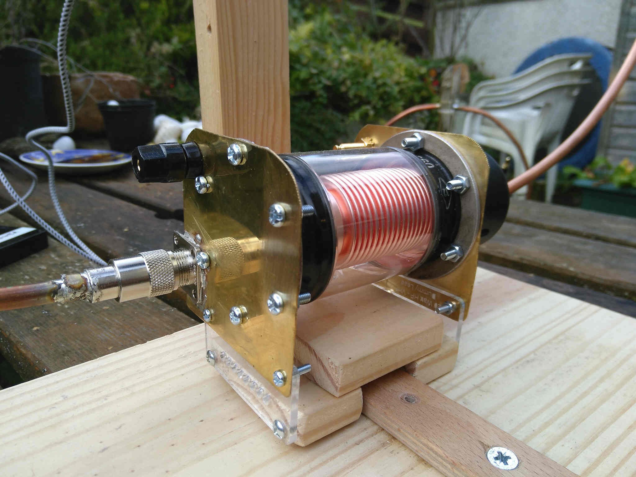
    Vacuum Variable Capacitor tuning circuit:

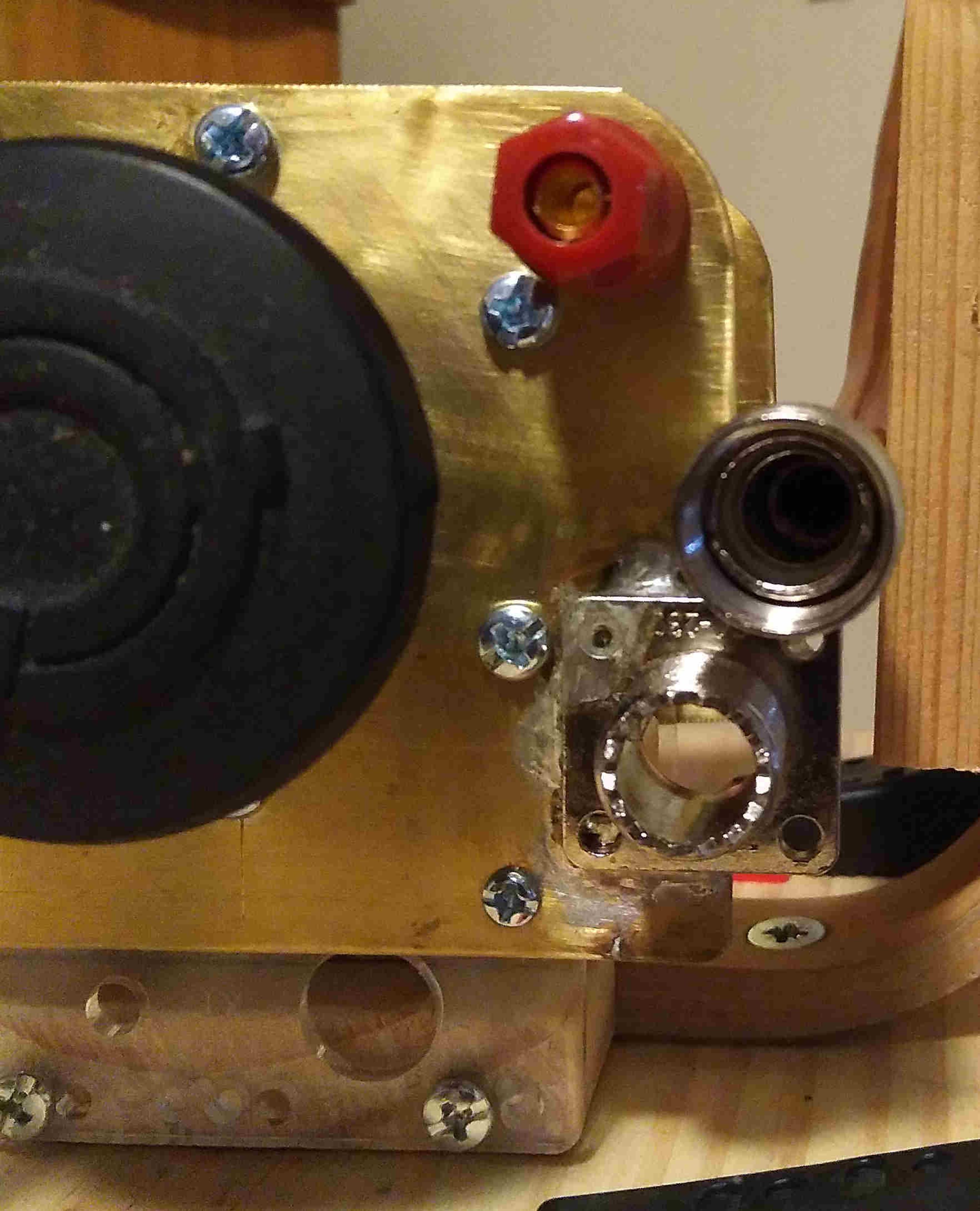
    I got this cap for a tenner at a junk sale - a real bargain. Brass plates and SO239 sockets connect it to the loop conductor. The big tuning knob came from a dead rice cooker ;-)

    I removed the centre connector of the SO239 and PL259 connectors by gently heating them up and then punching the plastic out. This avoids smelly surprises when soldering the thick pipes to the connectors and the sockets to the brass plates. The centre connectors are not needed anyway because most of the current is flowing through the surface of the loop (skin effect).

View all 5 project logs

Enjoy this project?

Share

Discussions

Similar Projects

Does this project spark your interest?

Become a member to follow this project and never miss any updates