The first 2 minutes : demonstration
Then 2 minutes explanation of how it works
The effect is GREAT but the working principle is very simple !
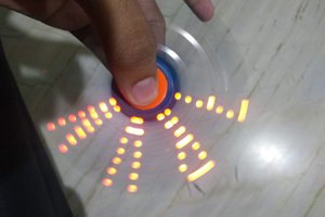
This display accomplishes an impossible task : everyone, in all directions, has the impression that the display is following him !!!
To make the experience fit your profile, pick a username and tell us what interests you.
We found and based on your interests.
The first 2 minutes : demonstration
Then 2 minutes explanation of how it works
The effect is GREAT but the working principle is very simple !
distort.pdeProcessing code for distorting images in order to be used by the Omnidirection Display. Please note that this code doesn't work with Processing prior to version 3.pde - 923.00 bytes - 10/28/2018 at 15:51 |
|
The build is obvious and you can imagine your own solution based on what you have available.
See the first video I uploaded
Create an account to leave a comment. Already have an account? Log In.
Thanks !
Before answering your questions, take a look at another page for this same project where I explain some ways to develop this display (I had to create this second page because it was required in order to submit it to hackaday contest).
https://hackaday.io/project/180349-omnidirection-display
Concerning your question : the LED panel is from a common outdoor solar LED light .
I don't have a measurement for the rotation speed :-\
The gap where the light emerges is about 5 mm wide.
It just worked, I didn't try to optimize things.
Good luck :)
PS: Vous avez un métier étrange ;)
Hey, i tried out your idea with a pringles can and a fan.
Worked well!
Here's a short clip:
https://photos.app.goo.gl/ma3NbCK37UcSdZpU6
Cheers
Ingenious !! and really a very big surprise.
What is interesting is the idea you have to attach it to the fan. I never taught of this idea as an addition or enhancement to another rotating apparatus. Perhaps it is an interesting direction of development.
I downloaded your video on my computer to keep it.
Thank you for sharing I really appreciate it.
Thanks, in the end it turned out to be easier than I thought to connect the can.
Just a very rough hole on the bottom of the can, that could slip through the existing bolt. It need not be very accurate, as I could slide then can around to center it before tightening.
Man, thats really good. Ive spent a lot of time obsessing over mechanical 3D displays.
This static case is really well done and accessible. Cheers
Thanks ! I have some thoughts about 3d applied to this display. ( I have also replied below about your proposition of the mirror )
Very clever, very interesting -- I am impressed and I like it a lot.
One question, though. Could you make this thing work with an LCD somehow? so that a moving image could be displayed...?
Thanks ! . Yes it is possible in principle to display an animated image, but it would be hard to make :( . The setup has to be very light because it is spinning very fast, an LCD screen doesn't fulfill this condition.
Use a small LCD and a device called a "slip ring" which lets signals through to a spinning device. eBay sells slip rings for very cheap -- the basic idea is that it has a ring inside with a wiper contact, for each wire that goes through it. As you spin one part, the wiper tracks across the ring and the signals pass through. I've not bought the eBay ones, yet, though, so I don't know how much electrical "noise" goes in with the signal. They appear to be made primarily to pass /power/ along, which can get away with being /very/ noisy...
eBay also has 2.6" TFT LCDs which 'speak' TTL serial for less than $10 USD -- you just hook up an Arduino/RasPi/whatever to them (with an Arduino, you use the TX/RX pins on the Arduino to 'talk' to the LCD) -- since you only need three wires, really (TX, power, and ground) -- you can use a very cheap slip ring. According to what I've read, they're 3.3v-signal-tolerant, so you can use them with a Raspberry Pi (which outputs TTL serial at 3.3v, as I recall) as well -- although you'll have to change the baud rate, those LCDs only work at 9600bps. There are ways of making them 'talk' faster (up to 115200bps, I think) -- but the faster they 'speak', the more problematic noise becomes... best to stick to 9600bps, even though that's very slow these days.
The idea I'm picturing is to belt-drive the Pringles can with the slit in it, using a pulley in between the can and the slip ring. You can use a big rubber band (the ones in K'Nex toys come to mind here) in between the can and the motor. Put the LCD in the can, opposite the slit. Wire it up with the slip ring and pass an image to it, spin it up, and see what happens. I don't see why it wouldn't work... I've been wrong before, though!
Don't spin the active electronics. If you do explore this route, spin light weight optics like mirrors.
@rbairos -- yeah, that doesn't work. The LCD has to spin with the slit. Think about it -- if you have a stationary LCD and a 45deg mirror, you end up rotating the image vertically (i.e. around an axis that is horizontal) as you move around the display. IOW, if you move you 180deg around the display (to the "back" -- to the extent that there /is/ a back) -- the image will be upside-down!
You /need/ the LCD-and-slip-ring setup -- and you need a *small* LCD -- or a terminal setup with a RasPi Zero / Zero W in there somewhere and a slow-ish serial connection (think "RS-232 Dumb Terminal" like a VT100 sort of a thing, or whatever weird $#!* protocol they use for those "USB" secondary displays you can buy these days) -- or something low-res-ish analog and a driver board -- because you can't slip-ring either (a) a massive parallel-connection scheme like most LCD panels use or (b) a massively fast serial bus such as eDP or HDMI -- in the first case, you would need an impractically ginormous slip ring setup (as many as 24 data connections, even before you get to power and ground!) and in the second, noise introduces so many artifacts that the display is unusable and unintelligible.
Something analog like VGA or composite / S-Video *might* work as a signal standard here, if you kept the resolution way down. You're almost certainly not going to get above XGA (1024x768) or WSVGA (1024x600 widescreen) with this, and even that sounds to me like "pushing it" territory. NTSC (roughly 440x486) video should be /very/ doable, though -- as should base-spec VGA (640x480). If you engineer the slip rings to NASA-grade specs (so to speak) you /might/ be able to push things up to 1280x720 (720p) or even 1366x768 (WXGA) -- but that's going to be one /very/ expensive slip ring. Custom engineering for things like that does /not/ come cheap!
@Starhawk Nice idea of slip ring ! . I have to solve challenges with static images and then consider video ( When I pass from idea to prototype I encounter many practical problems that really brake my enthusiasm for further developments ) @rbairos your idea of placing the LCD screen and rotating it horizontally and use a mirror at 45° is in principle OK. @Starhawk & @rbairos I think about an OLED display bendable like a sheet of paper but, even in principle, it may not work because the image has to be stable during one period of rotation ( the image has not to be displayed line by line while rotating ). Another solution ( that can be practical ) is to use an LCD projector placed at the bottom about the axis of rotation. As I said I have to concentrate my attention on static images and then think about video. Thanks for the comments !
@Starhawk You're making assumptions about how the optics would be setup.
(Perhaps you're replying to my earlier comment, which I edited to make more general).
There are no shortage of volumetric displays that arrange optics in various ways to project a static image on a rotating screen. The trade off however, is that you then require a quickly updating OLED/microled/dlp to compensate the image (rotating etc).
The electronics become more complex, but the mechanics simplify considerably.
That being said, there are probably some optics for this specific case that enable a static image.
Last year, I made several detailed simulations/renderings of a similar approach of a horizontal-parallax only tin-can display. In that case though, the slit was rotating, but 3 display's in a triangular setup inside the can was stationary, providing a 360 degree view of an 3D object (horizontal parallax only).
If you do use a slip-ring arrangement, all sorts of mechanical problems suddenly arise, as you mention. One of my prototypes spun an active display.
I began with a slipring, but abandoned that for a wireless power transfer ring that supplied power, and having the driving electronics spun as well.
Expect at least an order of magnitude slower rpm!
Thank you for sharing how you achieved the effect. I've been pondering how you did it for the last few days. Really cool.
Do the leds need to be PWMed/pulsed or is the slit small enough to get a sharp image?
The LED light is ON without modulation , it runs on battery (4.5 V) I got the LED light from an outdoor solar LED light. I used a small size pringles can , glued it to a DC motor ( It is a simple motor from a portable car vacuum cleaner : 5$). It is that simple ! Please see the video again and feel free to ask any questions because I don't know how other persons perceive this idea. And also stay tuned because I will post another video describing some ideas about future developments.
Thank you for the information. I saw some flicker in the video, so I wasn't sure. The flicker is probably due to rolling shutter. Nice touch using a Pringles can. Looking forward to the update video.
If the LED is on without modulation, why is it needed?
Why not just leave the top off the can?
Probably you haven't seen all the video , please go straight to 1min48sec or use this link : https://youtu.be/mNi4q7iUF7A?t=108
Hey, this is really cool! However the build is not obvious to me. Can you please clarify it a bit?
Probably you haven't seen all the video , please go straight to 1min48sec or use this link : https://youtu.be/mNi4q7iUF7A?t=108
Become a member to follow this project and never miss any updates

 Konstantin
 Michael Hawkins
 TinLethax
Great project ! Many side ideas :-)
Can you share more info about target RPM ? size of the Springle's hole ? Power of the LED ?
Thanks !