Here's some tips: don't use fritzing if you are going to print using seeed (a pcb printing service). As of 2018-11-04 fritzings gerber exports don't work with their service.
I ended up using easyeda, it even has a web interface if you're lazy. Or a linux client if you're not.
I designed one 100mm x 100mm pcb, you connect up to 3 of them by the dots on the sides, and the rows. This way you can save money and prevent extra pcbs since most places have a minimum pcb amount.
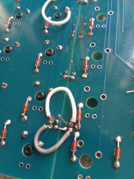
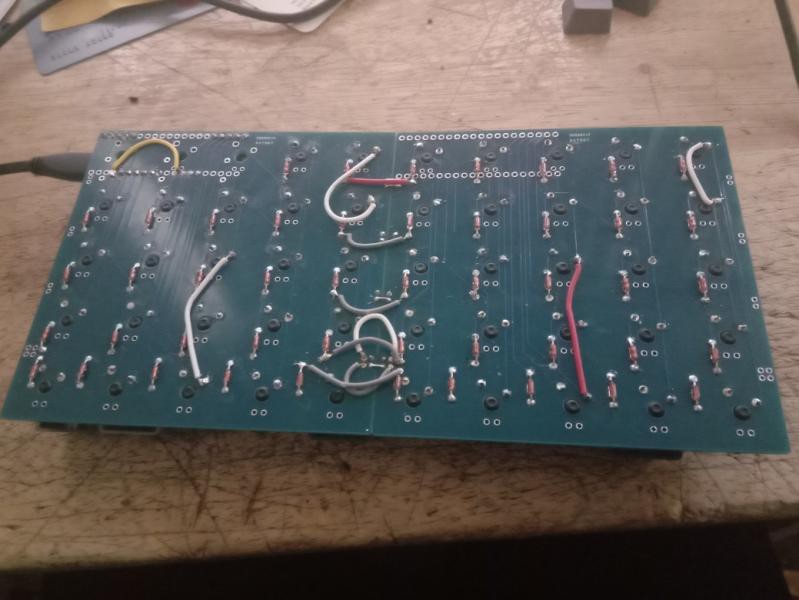
I missed two connections on my original design below. Oops. Didn't matter.
3
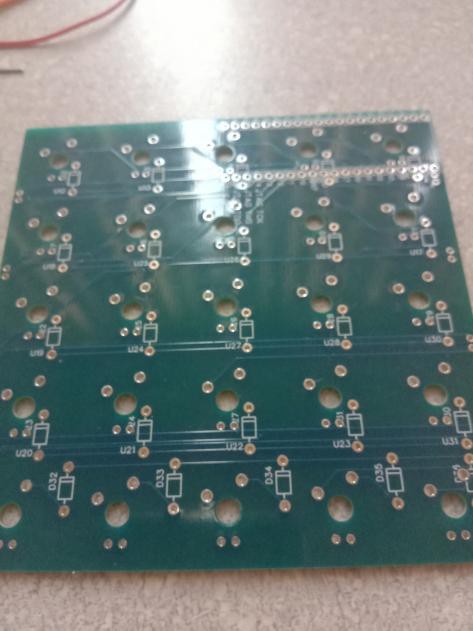
Print your PCB.
You can use something like seeed. Or if you made your pcb with fritzing use fritzings service.
4
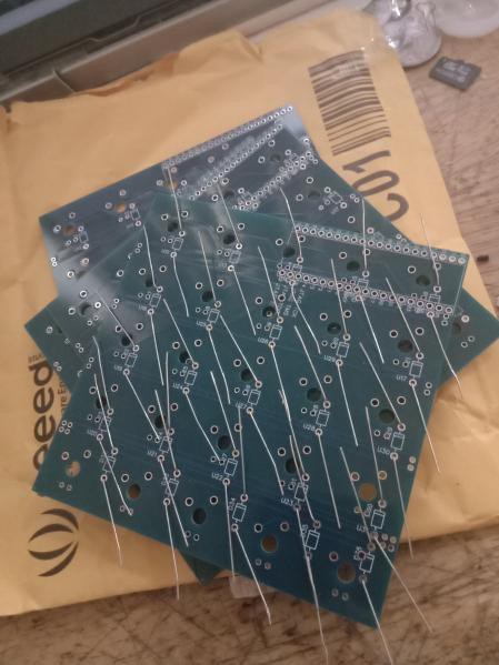
Attach Diodes
1n1448 is what I used.
Solder and clip them, try to keep the side the keys will go on flush.
5
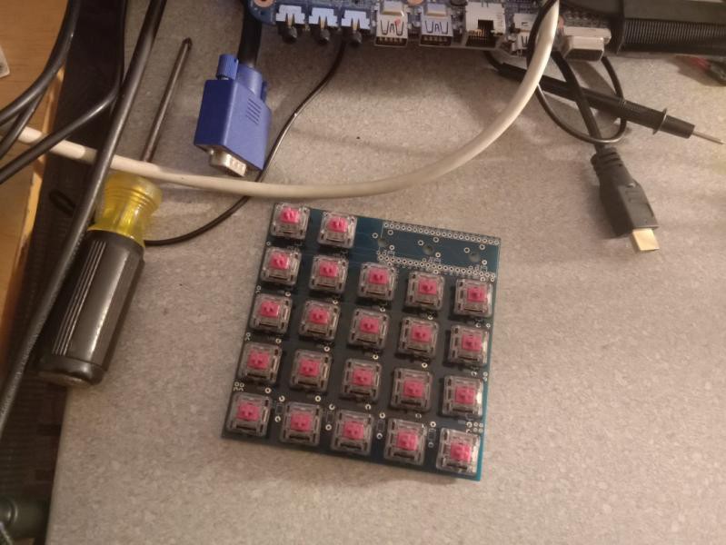
Solder on switches.
I used mod-m linear switches.
6
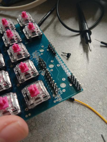
Solder on pins for the microcontroller.
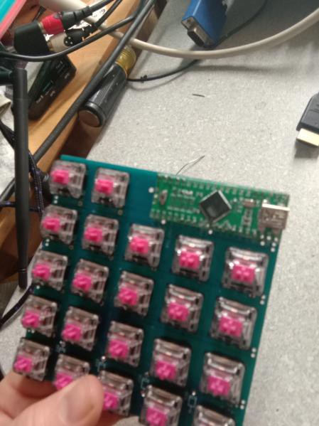
The pcb I designed uses teensy 2.0 ++
Heres the pins I chose to use.
7
Solder on the big boy microcontroller.
8
Repeat for as many other boards you want. But not more than 2 more boards, and not less than 0.
I forgot to take a picture, but theres another board, this time with all 25 switch spots fitted. I chose to do one more, for a total of 47 keys (a weird ass 40%)
9
Connect them.
Take some of the pins you snipped off from the diodes, or snip some more off perfectly good electronics if you're lazy. Or buy something real to do it. connect the boards together using there pins.
10
Fix the connections you missed when you were designing the PCB
 trisimix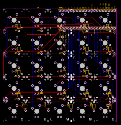
Discussions
Become a Hackaday.io Member
Create an account to leave a comment. Already have an account? Log In.