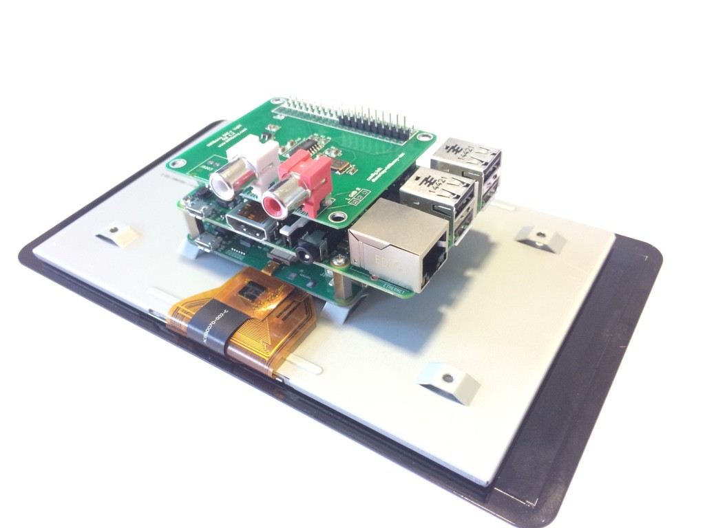
With the official Raspberry Pi Touchscreen, we were excited to find applications for it in our Max2Play system. Since audio applications have been one of our main focuses from the start, we immediately thought of a combination of sound card and screen. We had already created great bundles for both touchscreen and sound card solutions, but the combination was something we were still working on.The main connectors of the Raspberry Pi can only be used for one device at a time. So we had to get creative and can now show you the result.
With just a few tweaks on the standard Raspberry Pi Touchscreen and Case, we can now combine it with a powerful sound card directly on-board. When we incorporate these components into our Max2Play Image using the elegant Jivelite visualization and our own RPi display plugin, we get a great setup with all the features we know and love, great sound and a massive touchscreen to control it all.
Connect the Touchscreen and the Sound Card With the Raspberry Pi
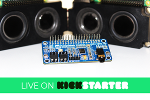
Just follow the instructions from your touchscreen and make sure everything is well adjusted using spacers and screws. Then put the sound card on top of the Raspberry using the GPIO connector bar. We are using a HiFiBerry DAC+ light for our system. Its affordable yet powerful nature combined with its small size makes it perfect for this project.
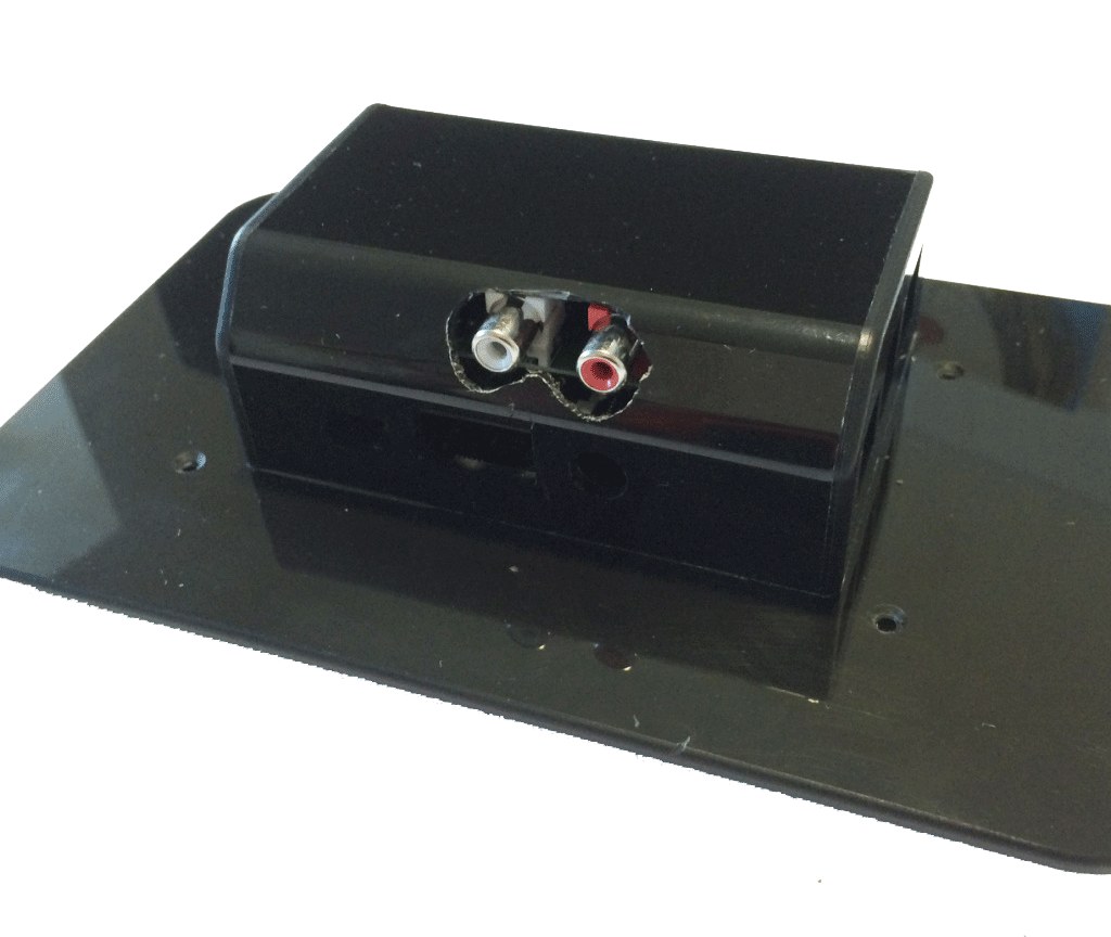
Drill Holes Into the Case for Your Sound Card's Output
Check the dimensions of your sound card's output and its distance from bottom of the touchscreen. With these specifications you can mark the area on the case that has to be removed in order to be able to connect your sound card Use a drill to bore a hole where you have marked the exits for the sound card. Then check if the case fits comfortably onto the system. If not, just extend the holes until there is no pressure on the case anymore.
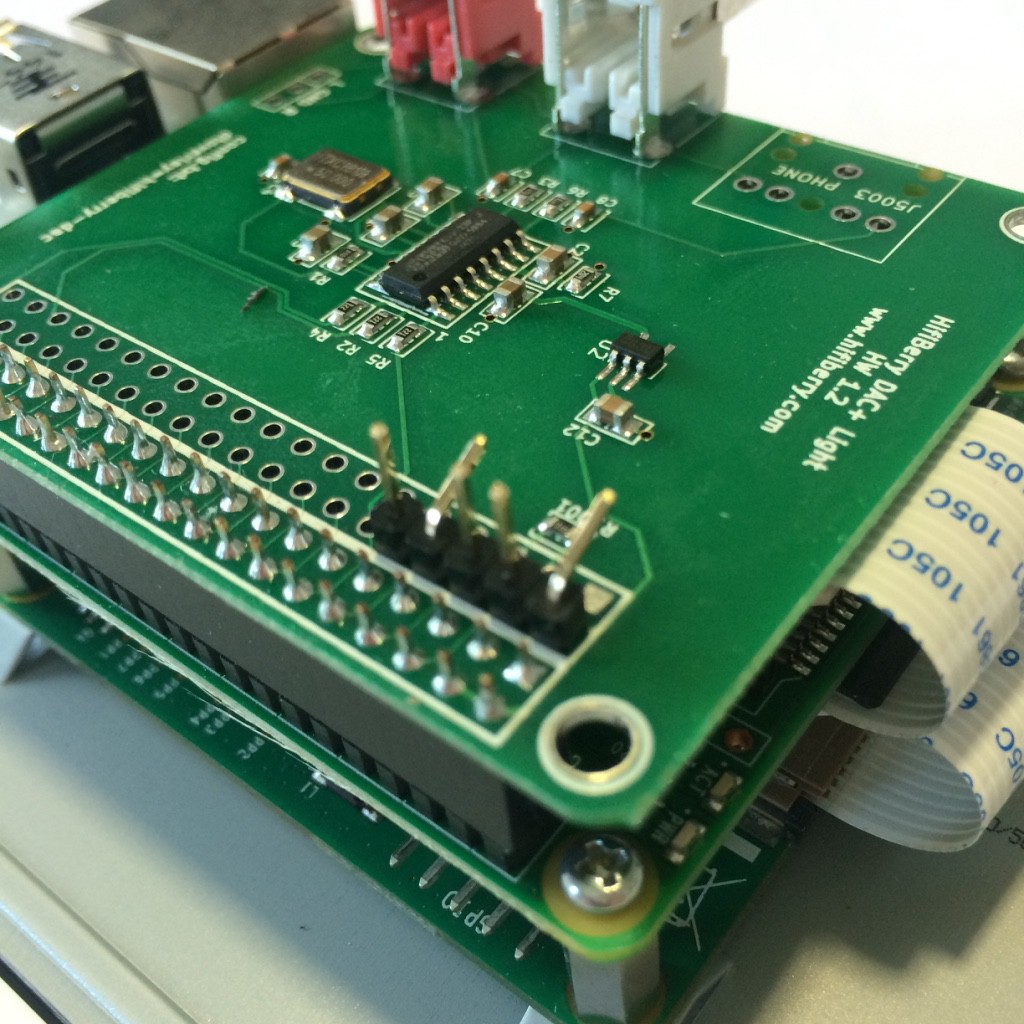
Since the two peripheries, screen and sound card, both need a lot of juice to run properly, we need to give the sound card an additional power source in the form of the 5 volt connector on the touchscreen. However we cannot connect the two yet since the connectors on the sound card are only for the Raspberry Pi.
That is why we need to solder a little line of five connectors onto the top of our sound card. We just need two connections for the power supply, the first and third hole, so we only need to solder in two places. Once those two are rightly connected and sit strong on the sound card, we need to bend the connectors a little in order to not have them stick out in our case.
Now that this new ridge is added and conformed to the rest of the system, we just need to connect the two cables and all the hardware is in place.