-
Demo Build underway
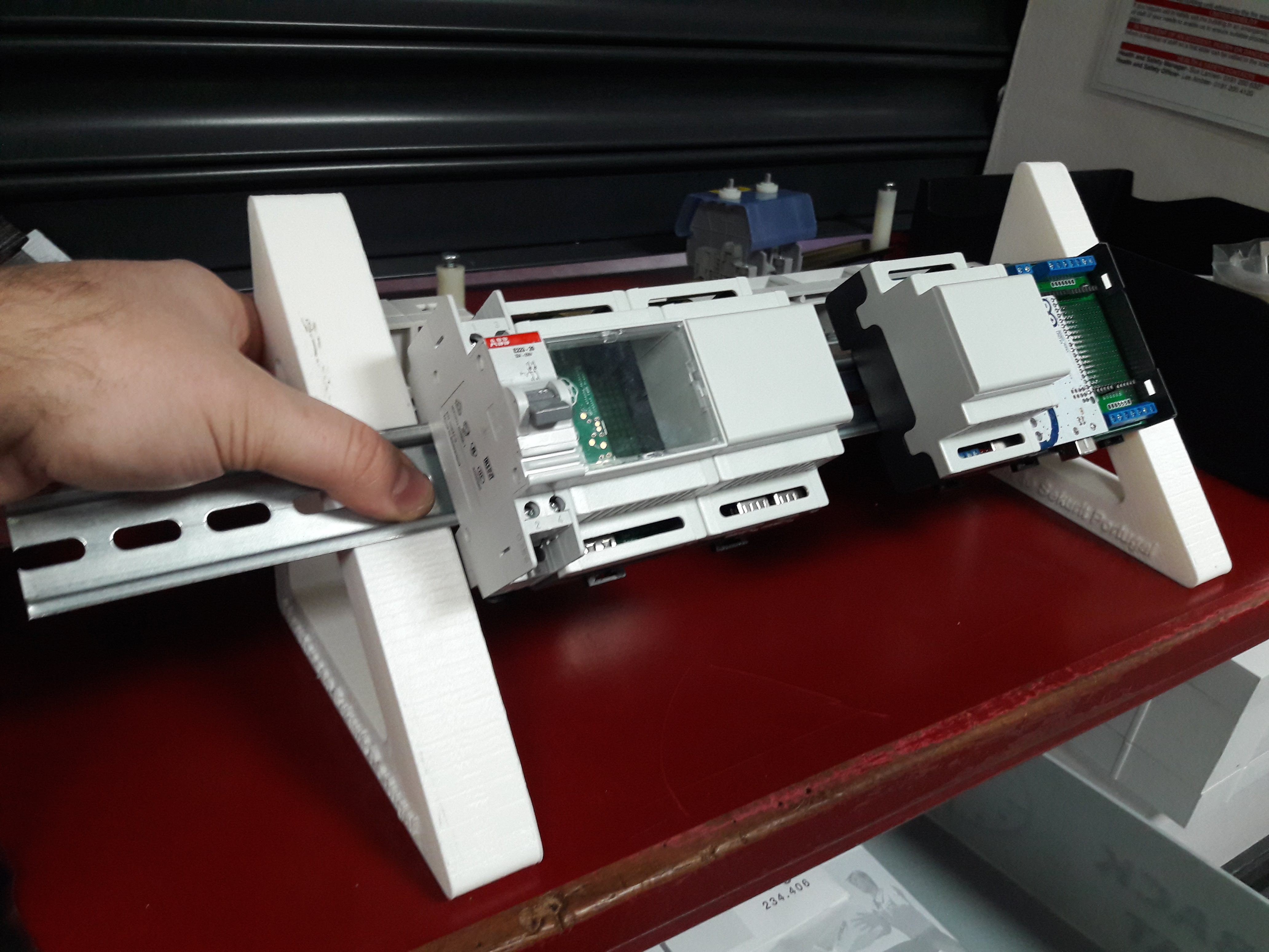
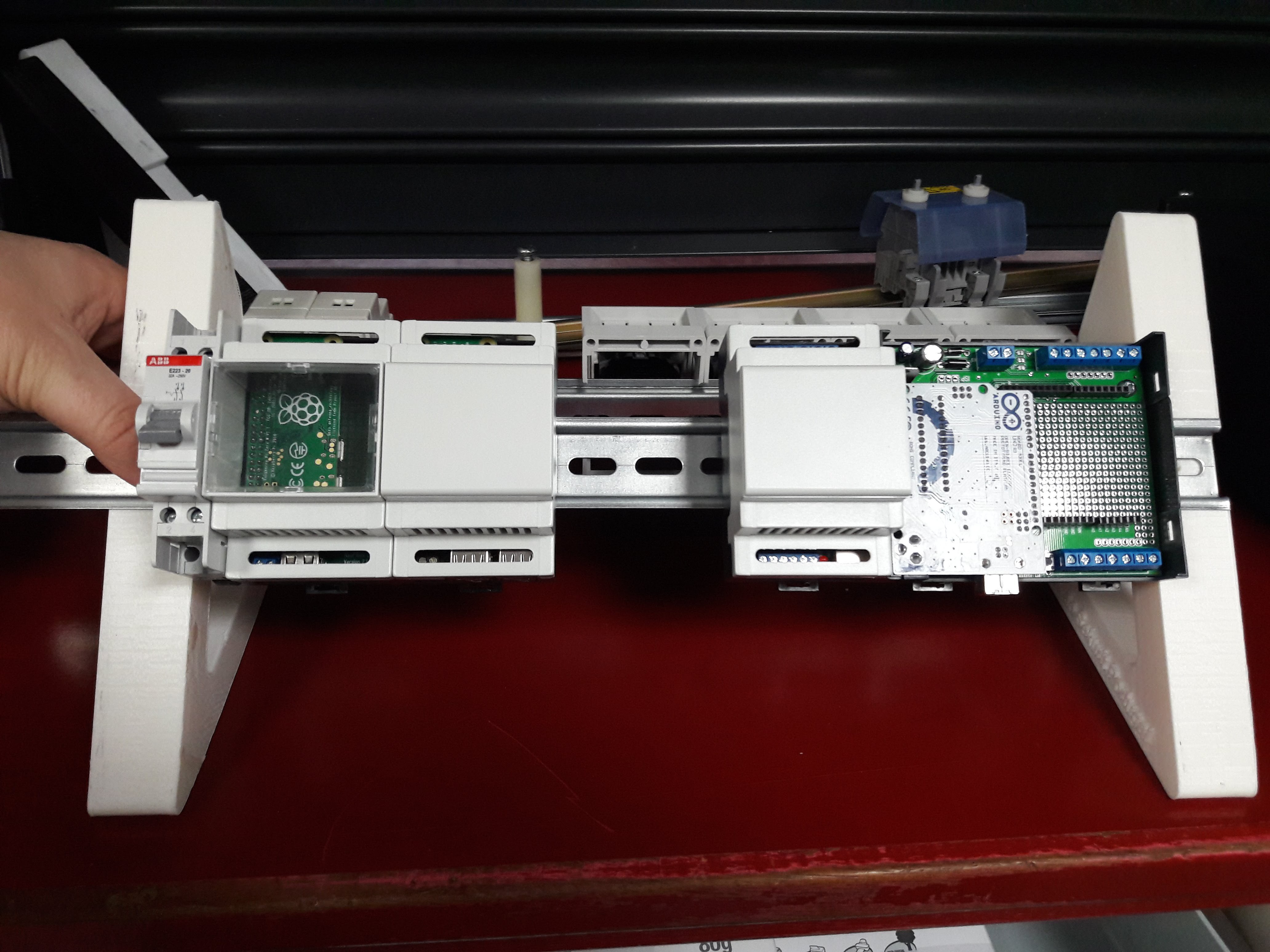
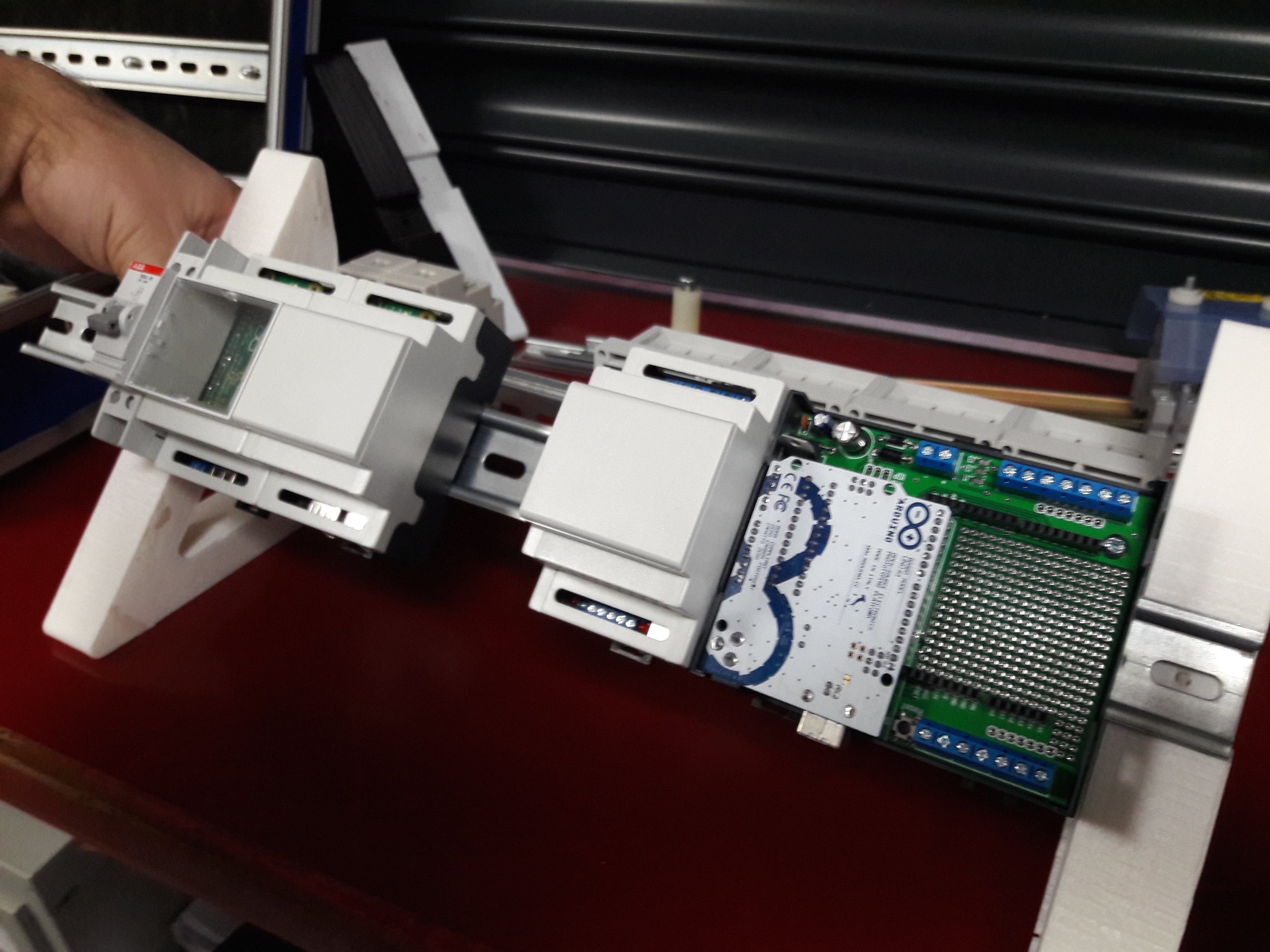
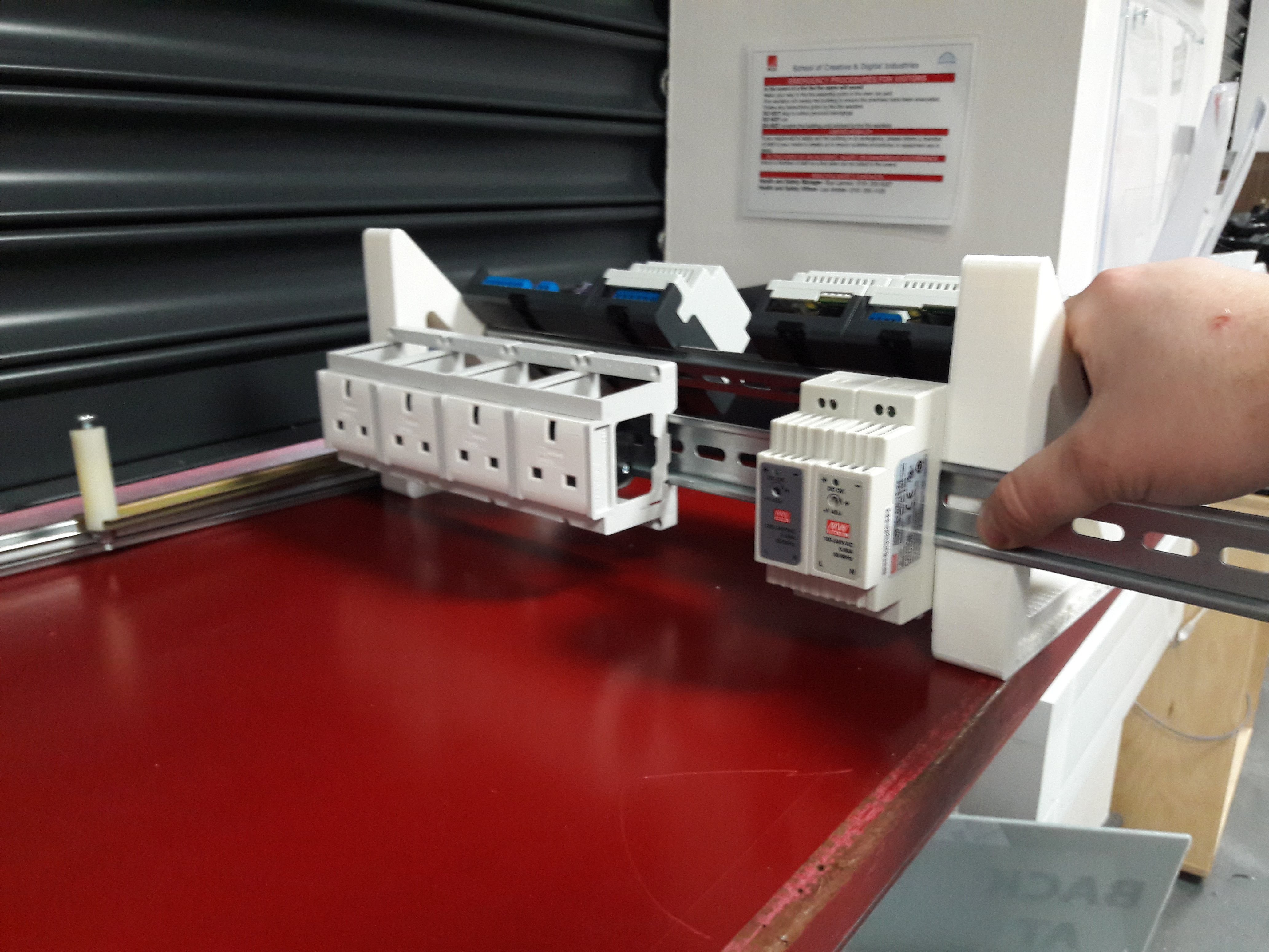
01/12/2018 at 23:52 • 0 commentsWork has begun on putting together a demonstration rail for the Aquariumatic.
The rail setup consists of two rails on some triangular mounts (3D printed, sourced from Thingiverse). the Front rail consists of the units (Pi Server, Arduino-based controller, and eventually two NodeMCU based modules to simulate extra Controller units) and the back rail consisting of the Power distribution, power regulation (both 5v and 12v) and 4 rail mountable UK plug sockets for attaching the aquarium hardware such as heaters, lights and pumps (controller by the arduino controller).
Hopefully it will be wired up and running in the next week or two :-)


-
Parts Acquisition and demo build
12/28/2017 at 02:07 • 0 commentsFirst and Foremost Merry Christmas!
Just a quick update regarding this project.
I have been accumulating all the parts I require to build a portable demo rig of this project and it has took some time. Today I have finally ordered the last pieces to be able to finish off this rig on my return to work in the New Year.
The rig is going to be built upon a two DIN rail system mounted to two triangular mounts; the front rail will hold the Pi, Arduino and relay modules, and the back rail will hold the mains power distribution, 12v power supply, 5v power supply and 4 rail mountable 13A sockets.
This will keep the project small and compact, will keep the wiring neat and hidden between the rails, and will look great on my desk :-)
If space allows I am also going to mount the original Aquariumatic slave module that only worked via USB, and I will rewrite the old code for the unit to be supported on the current Pi. It'll allow me to show the progression of the project.
Pics will come in the new year; all parts apart from the 13A socket are currently in my possession so we are good to get going!
-
Marching on
10/18/2017 at 23:57 • 0 commentsTonight has been a long but rewarding session. Spent the last few hours writing and rewriting functions for my #Aquariumatic project. Tonight's focus has been how data is shared amongst devices in the setup.
Previously the setup focussed on the slave units sharing JSON packets (containing temperature, pH and other sensor information, relay states and other device information) to a webserver to be displayed to the user in a web page. This was slow development; the first device was built around an Arduino uno and used serial to send data (very messily before I started using json), and has steadily improved as I've learned more.
Following tonight's work the JSON packets have been heavily formatted and are now fully compatible with the MQTT scripting I have also been working on, as well as dislayable on a simple webpage served by the Unit itself for standalone operation. Now I have got this part playing nicely I can reinstate the rest of the functionality to the unit and can finally say the slave unit software is complete.
I have also been working hard on the Hub(server/broker) Unit that will tie all the slaves together, and have a cracking setup based on the DietPi os. Once this is finished I'll be able to leave the software and turn my attention to getting the prototyped units recreating in product form.
Earlier in the week I submitted proposal to a manufacture to try and turn my prototypes onto finished products.
I cannot effing wait!
-
Development update
10/12/2017 at 00:51 • 0 commentsTonight I've had a bit of time to have a look at how to reinforce my network communication between the various units that could be used to make up an Aquariumatic install.
After hearing a lot about MQTT (and subsequently watching a lot of related videos) I decided that integrating the protocol would improve my communication between not only the devices but the user.
I have installed an MQTT Broker (like a server) onto a Pi and it runs great. I'll be able to run this on the Pi Powered hub in my setup. The original plan was to go figure the Pi as an Access Point and have all the devices connect to it; this is great, as all the devices will have access to the broker.
I've also had an MQTT client running on an ESP8266, successfully publishing data to a test channel. I've installed a client on my android phone and it was possible to subscribe to the test channel and see the data updating.
While early days I'm really excited at the prospect of rewriting my hub and controller scripts and exploring what MQTT can bring to my setup.
I'm going to need to write a python MQTT client to take the published data from the channel/channels on the Pi and use it to populate a Web GUI with useable data for the user.
Also I'd like to publish data in a JSON string to a channel but I'm not sure if that's possible - I'll keep working on it. Id also like to publish data in a more user-friendly manor to a second channel.
Also very soon I am going to be liaising with a company with a great pedigree in taking ideas and making in them into professional products, with a view to creating the product versions of my prototyping setups.
I'm really hoping that u can keep this momentum up and bring this to life very very soon!
-
Behold: PROGRESS!!
09/06/2017 at 20:16 • 0 comments
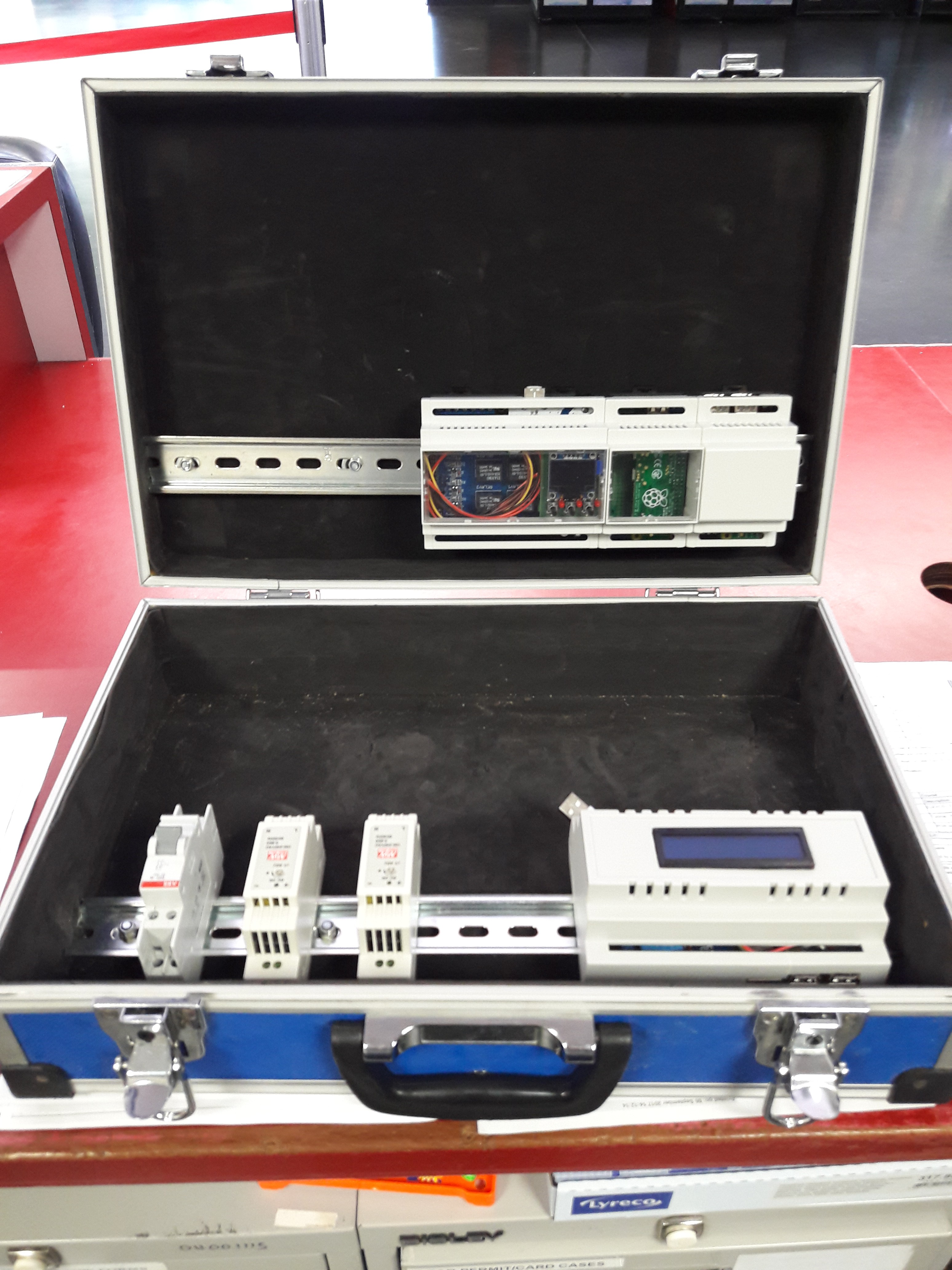
On the top rail in my portable case is currently my ArduiBox Open and two Raspibox Zero models, all by @Hartmut Wendt . These units will demo my #Aquariumatic setup and also my General Home Automation core. I'd like to add some more units to this rail to demonstrate the multi-unit wireless setup that is capable with both projects.
The bottom rail will contain all power and on/off switches to the left of the rail, and the rest of the rail will be dedicated to other projects (such as this Pi/4xRelay/LCD build I'm going to use to simulate the Bin Sensor unit I currently have running in a factory for testing). For power (for now) I'm going to be running power into the switch, then to the two variable power supplies (set at 12v and 5v) and then split to all the units in the case.
I'll then look to add some covering to mask the cable runs.
Happy with today's Progress, I must say! -
Demo rig Update
08/26/2017 at 22:04 • 0 commentsin past posts I have alluded to the idea of creating a portable 'demo rig' for the Aquariumatic; a fully functional setup that is easily portable and can be quickly set up to demonstrate to anyone who is interested in seeing the system work.
I have finally settled on an idea to build up such a case, and will be getting stardom on it next week hopefully.
The case itself is a small blue flight case with a workable width of around 16", and the plan is to mount a DIN rail in the lid of the case and one in the Base of the case. The rail in the lid will hold the Aquariumatic setup of one Control unit and also on Pi Hub unit; when the case is opened it will be easily displayed.
This rail will be powered by a DIN rail variable power supply.
the rail in the Base of the case will hold a switch, another variable power supply and have space to add further components.
I am also going to fit some additional Wemos D1 boards with arduino lcd Shields to act as dummy control units. These will be handy when demonstrating how the Pi Hub handles multiple tank data sources.
Eventually I would like to have power included in the display case, but until then I am happy to plug the case into mains to power it.
I am going to run mains to the switch and then from the switch to the two power supplies; this way I can control the whole unit from the one switch.
I'm open to any suggestions on how to assemble this little rig. Feel free to comment!!
Cheers!
-
DFROBOT Wifi Bee ESP 1.0
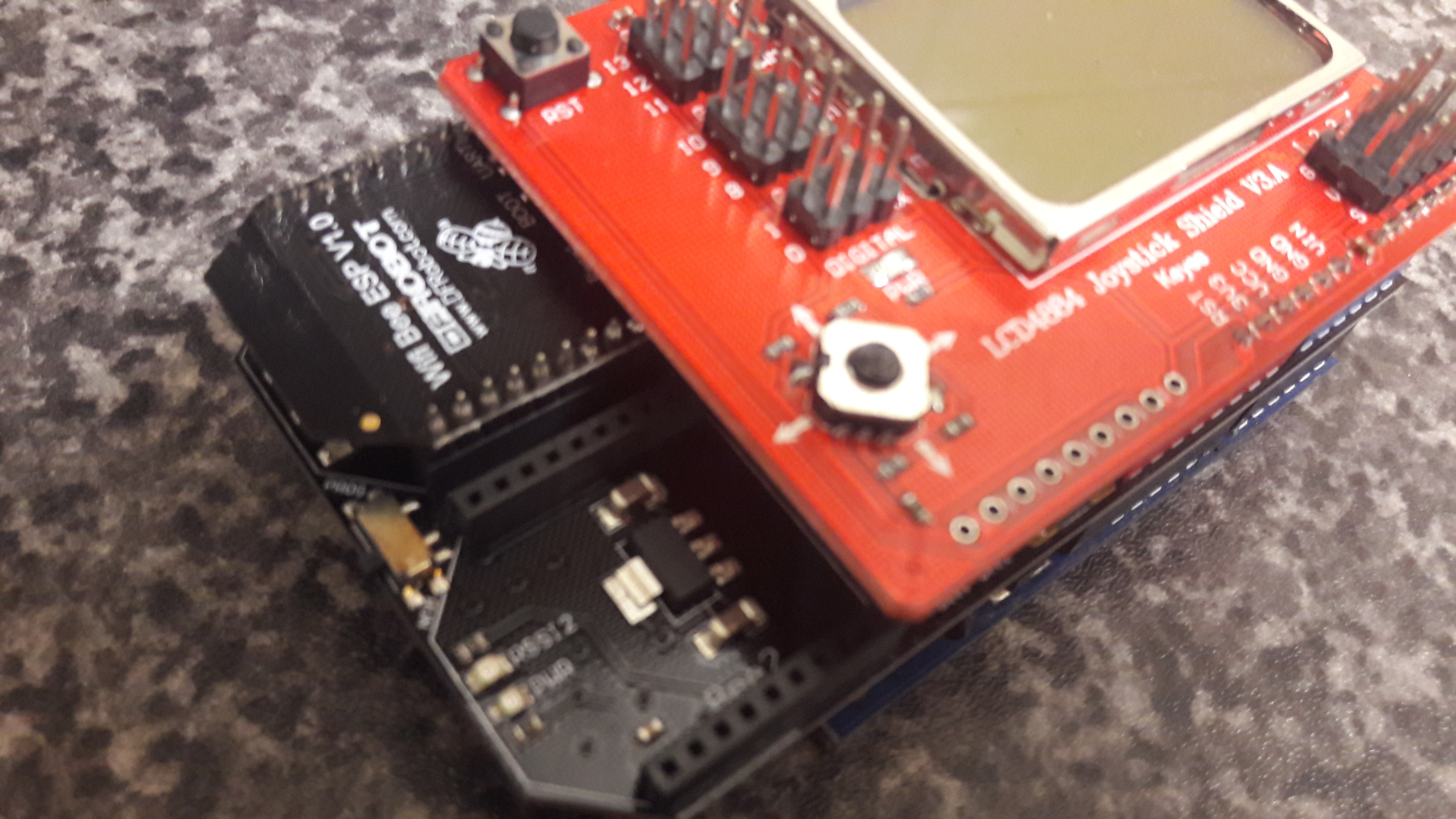
08/05/2017 at 01:22 • 0 commentsA month or two ago I was lucky enough to he selected to trial the titular wifi module by dfrobot:I applied for the review programme as I was looking for some simple methods of adding wifi to my arduino-based control unit. The module came a while ago, but I chose to order a Bee-compatible Arduino shield to make connecting the board to the Arduino easy. To test the module out I am going to add it to an Arduino Uno with a Nokia display shield to create a 'test control unit' to fire sample data to my Hub unit when demonstrating my multi-tank setup:
Using the WiFi Bee is fantastically simple when using Bee-compatible boards; just plug it in. Although it has a lot of pins I was relieved to find it only uses a handful; 3.3v, ground, and two pins for serial.
The shield I have bought in the above picture has two Bee ports; one for connecting to the hardware serial port on the Arduino, and one for connecting to a software serial port.
I have opted to use a software serial port for it, leaving the hardware serial port clear for uploading sketches without having to remove it.
Next step I will tweak my code to work with the Uno (currently written for a Wemos D1) and report my findings here.
If the code is easily tweaked I may opt to use my Arduino back in the control unit and use the Wifi Bee for wifi communication. The Arduino enclosure I am using (the ArduiBox by @Hartmut Wendt ) features a nice open prototyping area meaning i could easily solder the Bee in and use it along with my Relay shield.
So far - loving it!
-
Software work continues
07/19/2017 at 22:29 • 0 commentsI've been quiet for quite a while on here, but work is still underway.
I have been focusing on writing and rewriting the sketches for the monitor units; at the moment the units work using a Wemos D1 to monitor sensors and relays, display the data on a simple Web page and also serve the data on a json page.
This means the monitors can operate standalone (for home use or for single tank operation) but can also operate as part of a network of monitors via the Pi-powered hub.
I've written a nice little python function which is capable of scraping json data from the json pages. This means I can easily get hold of each monitor 's data for display on a single Web page, and can also be easily uploaded to anot iot site.
I will aim to post more regularly!
-
Wemos <-> Uno Pins
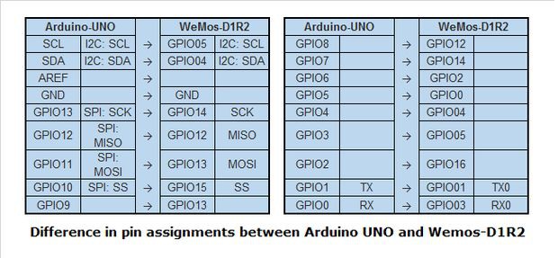
06/15/2017 at 14:44 • 1 commentThis is just a quick map to show how the pins differ on the Wemos D1 compared to the Arduino Uno.
They share the same footprint but their pins are somewhat different.
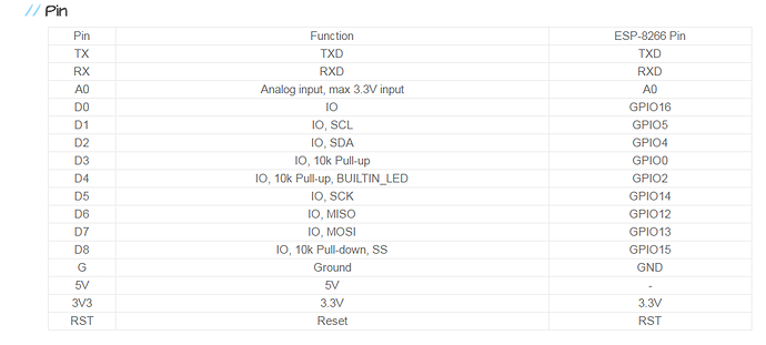
For my project I need to work out which Pins trigger the relay shield's 4 relays and also the maps for the remaining digital pins for connecting the pH sensor and temperature sensors.
the i2c pins are also required for running the oled screen and buttons.
Work is underway with the Wemos D1 code. The device will run a webserver to display data locally for users, and will also offer a json page for the Pi to collect data.
Good times!
-
Current Build
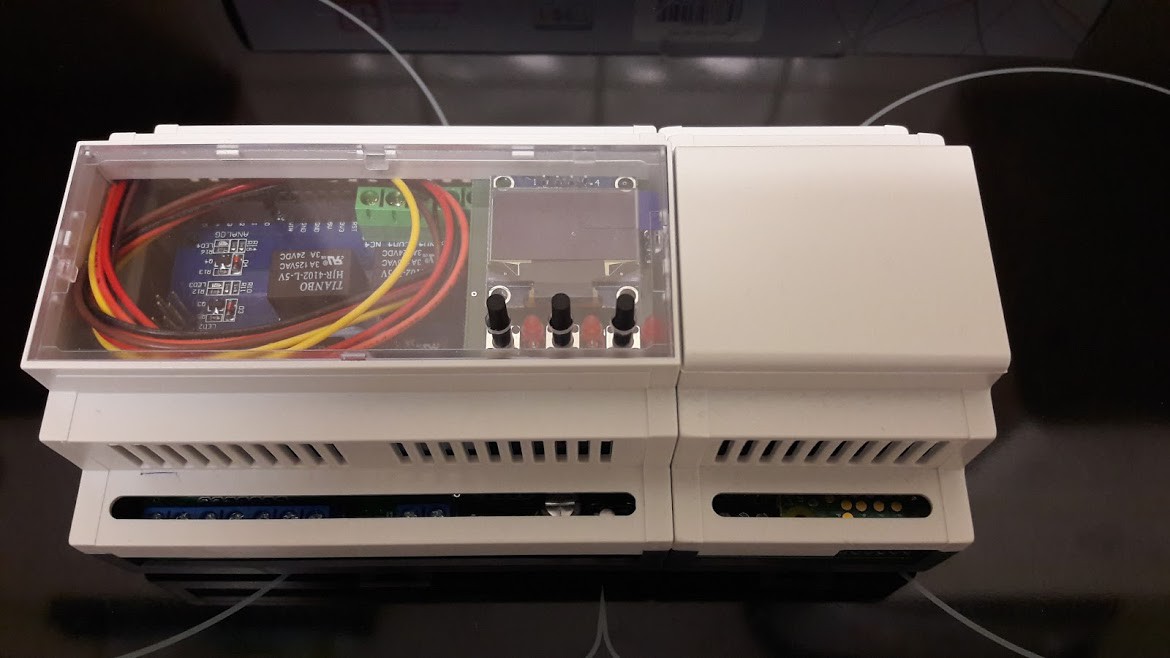
06/15/2017 at 14:29 • 2 commentsI just wanted to add a picture showcasing my current build using my enclosures from @Hartmut Wendt:
This thing is going to look incredible when mounted in it's display case on the DIN rail!
The DIN rail power supply has arrived today, so I can hopefully start to put together my case as soon as I have the rail fitted.
Mains will be connected to an on/off switch I have, and that switcxh will route the power to the relays and also to the power supply. The power supply will then power the Pi Zero W-based Hub and the Wemos-based Control Unit.
:-)
Aquariumatic
Automated aquarium monitor with Web GUI. daisychain units can control multiple tank all from the one master unit. PI/Arduino/ESP Powered
 Craig Hissett