Close
0%
0%

nedoPC-5

DIY personal computer built around 32-bit version of RISC-V processor

Public Chat
Similar projects worth following
nedoPC-5 is FPGA implementation of RISC-V 32-bit integer subset with retro-style simple computer around it. No Linux yet - may be later...

Why did I start this? It's obvious - people need simple and inexpensive RISC-V computer to play with to know new RISC generation better - it's a future anyway :)

Project was started on November 18, 2018 when I played  with very compact emulator of RV32I[MA] that @Frank Buss shared in Hackaday FPGA chat:

https://gist.github.com/FrankBuss/c974e59826d33e21d7cad54491ab50e8

it's based on RISC-V emulator from Fabrice Bellard ( https://bellard.org/tinyemu/ ) but supports only RV32I subsystem (with optional RV32M and RV32A subsystems) and turned into single text file with 1.5 thousand lines of C code. It's even able to pass all 55 compliance tests for RV32I and run Zephyr RTOS examples! So I started from this little emulator with the same MIT-license and converted it to pure C:

https://gitlab.com/nedopc/npc5

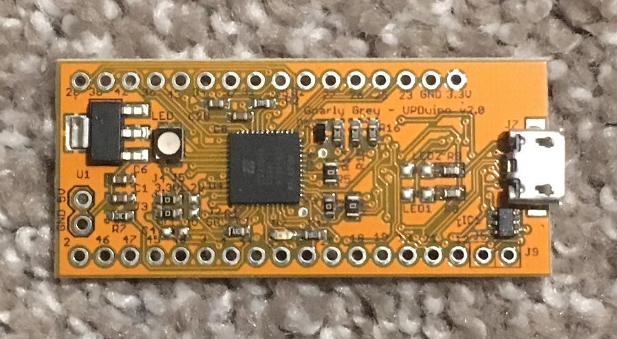
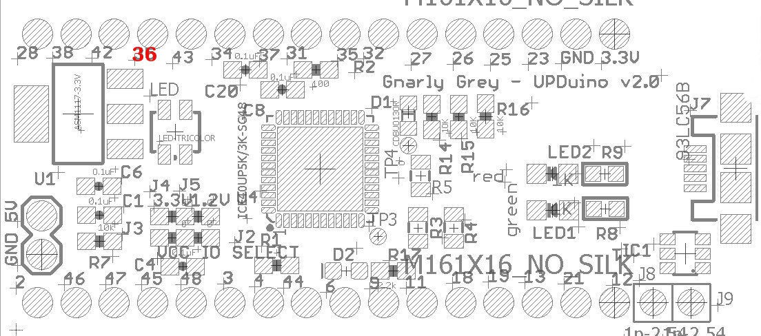
Then I wrote my own Verilog implementation of RV32I for UPDuino v2.0 board with iCE40UP5K FPGA:
Documentation has some mistakes, so I fix them as I find them:
RV32I subset is only 1 page of instructions (captured from official spec):
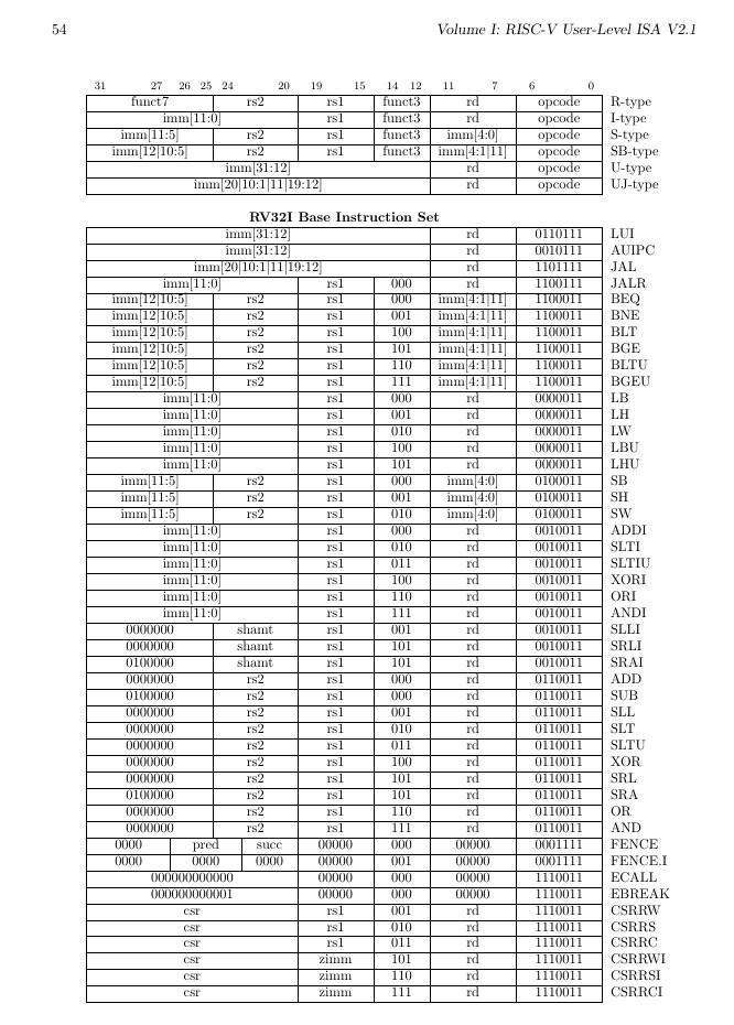
As you can see opcode is in 7 lowest bits - as we can see bits 1 and 0 are always 1s because of interesting approach to instruction set extension:
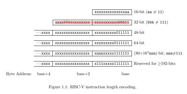
Also they have divided instructions to families this way (highlighted what was used for RV32I):

UPDATE: Article on Hackaday: https://hackaday.com/2019/11/19/emulating-risc-v-on-an-fpga/

iCEcube2-retro1s.tar.xz

Retro-V v1.0.0 soft core running on 12 MHz + test "Hello RISC-V!" with serial output (115,200)

x-xz - 4.13 MB - 12/30/2018 at 07:21

Download

iCEcube2-retro1t.tar.xz

Retro-V v1.0.0 soft core + test "Hello RISC-V!" with 8-bit output

x-xz - 4.08 MB - 12/13/2018 at 04:57

Download

  • Adding serial output instead of LEDs

    SHAOS12/30/2018 at 07:33 4 comments

    Full project for iCEcube2 software for iCE40UP5K-SG48 FPGA on UPDuino v2.0 board:

    https://cdn.hackaday.io/files/1623976947993248/iCEcube2-retro1s.tar.xz

    It's Retro-V v1.0.0 soft core with the same "Hello RISC-V!" test program, but running on external 12 MHz (taken from 2nd pin from the right bottom) and with RS232 sender ( also provided by @Frank Buss ):

    https://github.com/FrankBuss/adc4/blob/master/DDR3_RTL/rs232_sender.vhd

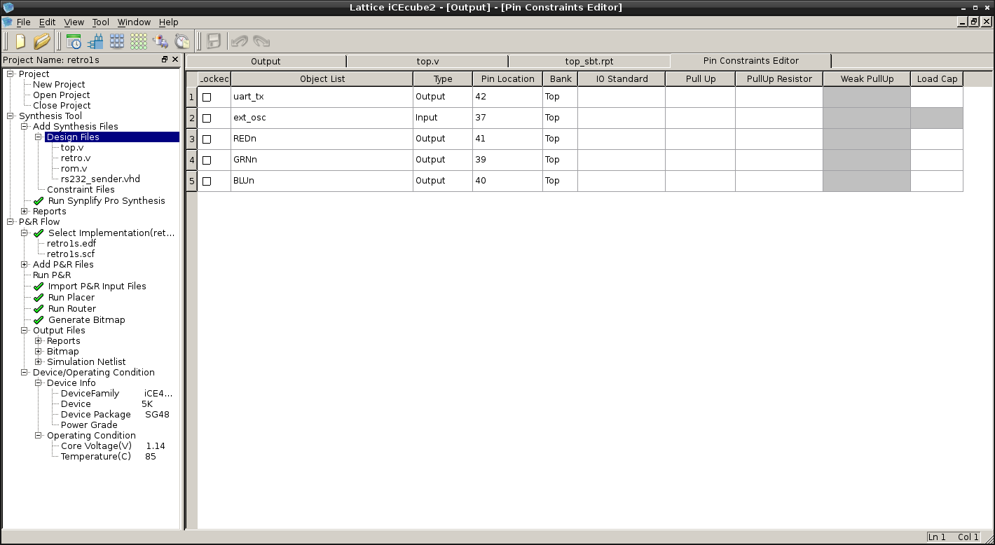
    12 MHz should be connected to pin 37 (7th pin from the left top) and pin 42 is TX:

    This is top.v that connects everything together (RS232 sender puts CPU on hold every character while busy):

    module top(ext_osc,uart_tx,REDn,BLUn,GRNn);
    input wire ext_osc; // 12 MHz
    output wire uart_tx;
    
    output  wire        REDn;       // Red
    output  wire        BLUn;       // Blue
    output  wire        GRNn;       // Green
    
    reg [27:0]  frequency_counter_i;
    
    wire [15:0] address;
    wire [7:0] data,dataout;
    wire clk,wren,hold,res;
    
    always @(posedge ext_osc) begin
        frequency_counter_i <= frequency_counter_i + 1'b1;
    end
    
    assign clk = ext_osc;//frequency_counter_i[22];
    
    retro cpu (
    .nres(1'b1),
    .clk(clk),
    .hold(hold),
    .address(address),
    .data_in(data),
    .data_out(dataout),
    .wren(wren)
    );
    
    //assign addrout = address;
    
    assign res = (address==16'h0)?1'b1:1'b0;
    
    // RS232 sender by Frank Buss:
    // entity rs232_sender is
    //    generic (
    //    system_speed, -- clk_i speed, in hz
    //    baudrate : integer); -- baudrate, in bps
    //    port (
    //    clk_i : in std_logic;
    //    dat_i : in unsigned(7 downto 0);
    //    rst_i : in std_logic;
    //    stb_i : in std_logic;
    //    tx    : out std_logic;
    //    busy  : out std_logic);
    //end entity rs232_sender;
    
    rs232_sender #(12000000,115200) TX (
    .clk_i (ext_osc),
    .dat_i (dataout),
    .rst_i (res),
    .stb_i (wren),
    .tx (uart_tx),
    .busy (hold)
    );
    
    //rom #(10) prog (clk,address[9:0],data);
    
    rom prog (address[7:0],data);
    
    SB_RGBA_DRV RGB_DRIVER (
          .RGBLEDEN (1'b1),
          .RGB0PWM  (hold),//GREEN
          .RGB1PWM  (clk),//BLUE
          .RGB2PWM  (wren),//RED
          .CURREN   (1'b1), 
          .RGB0     (GRNn),
          .RGB1     (BLUn),
          .RGB2     (REDn)
    );
    defparam RGB_DRIVER.RGB0_CURRENT = "0b000001";
    defparam RGB_DRIVER.RGB1_CURRENT = "0b000001";
    defparam RGB_DRIVER.RGB2_CURRENT = "0b000001";
    
    endmodule
    

    Serial output configured as 115,200 8N1 and it's printing this in terminal:

    Hello RISC-V!
    Hello RISC-V!
    Hello RISC-V!
    Hello RISC-V!
    Hello RISC-V!
    Hello RISC-V!
    Hello RISC-V!
    Hello RISC-V!
    Hello RISC-V!
    

    According to iCEcube2 output, soft CPU here can run on up to almost 20 MHz:

    #####################################################################
                         Clock Summary 
    =====================================================================
    Number of clocks: 1
    Clock: top|ext_osc | Frequency: 19.98 MHz | Target: 36.62 MHz
    =====================================================================
                         End of Clock Summary
    #####################################################################

    But RISC-V program is still running from combinational ROM, so it is not yet a REAL thing with variables (other than registers), stack etc...

  • Video of the 1st test

    SHAOS12/25/2018 at 08:04 0 comments

    Note: LEDs are inverted (because connected to power)

    Now I need to add a serial interface instead of 8 LEDs to try more advanced programs :)

  • 1st test on FPGA

    SHAOS12/13/2018 at 05:14 0 comments

    Full project for iCEcube2 software configured for iCE40UP5K-SG48 FPGA device:

    https://cdn.hackaday.io/files/1623976947993248/iCEcube2-retro1t.tar.xz

    It's Retro-V v1.0.0 soft core with "Hello RISC-V!" test program ( provided by @Frank Buss ) that is stored as ROM:

    /*
     Frank Buss: compile like this: riscv32-unknown-elf-gcc -O3 -nostdlib test1.c -o test1
     or
     riscv64-unknown-elf-gcc -march=rv32i -mabi=ilp32 -O3 -nostdlib test1.c -o test1
    */
    void _start()
    {
        volatile char* tx = (volatile char*) 0x40002000;
        const char* hello = "Hello RISC-V!\n";
        while (*hello) {
            *tx = *hello;
            hello++;
        }
    }


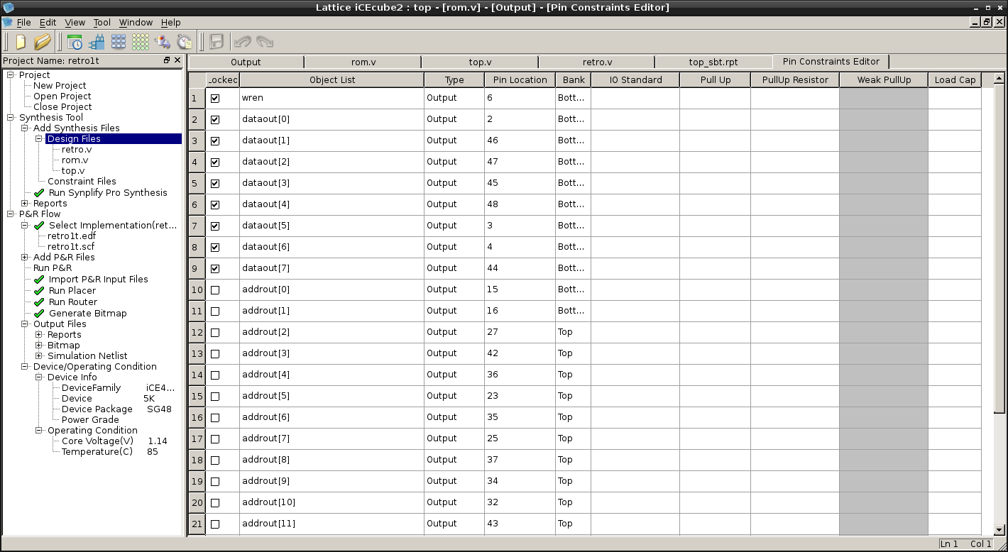
    I locked data output 8-bit bus to bottom-left pins of UPduino:

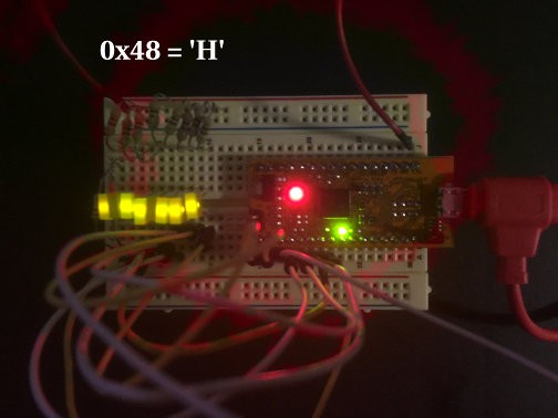
    8 LEDs connected to them will "print" message character by character (LEDs show inverted bits):

    So it prints:

    01001000 = 0x48 = 'H'
    01100101 = 0x65 = 'e'
    01101100 = 0x6C = 'l'
    01101100 = 0x6C = 'l'
    01101111 = 0x6F = 'o'
    00100000 = 0x20 = ' '
    01010010 = 0x52 = 'R'
    01001001 = 0x49 = 'I'
    01010011 = 0x53 = 'S'
    01000011 = 0x43 = 'C'
    00101101 = 0x2D = '-'
    01010110 = 0x56 = 'V'
    00100001 = 0x21 = '!'
    00001010 = 0x0A = '\n'
    

    Source code is also uploaded to GitLab:

    https://gitlab.com/shaos/retro-v/tree/master/FPGA/iCEcube2-test1

    As you can see CPU clocked by 24th bit of the counter driven by high-speed oscillator, so it's like 16 millions times slower - in order to visually see what is going on there - blue blink is clock, red blink is write out (a character on 8 LEDs).

    Design statistics:
    ------------------
        FFs:                  336
        LUTs:                 2211
        RAMs:                 4
        IOBs:                 25
        GBs:                  5
        PLLs:                 0
        Warm Boots:           0
        SPIs:                 0
        I2Cs:                 0
        HFOSCs:               1
        LFOSCs:               0
        RGBA_DRVs:            1
        LEDDA_IPs:            0
        DSPs:                 0
        SPRAMs:               0
        FILTER_50NSs:         0
    
    Logic Resource Utilization:
    ---------------------------
        Total Logic Cells: 2313/5280
            Combinational Logic Cells: 1977     out of   5280      37.4432%
            Sequential Logic Cells:    336      out of   5280      6.36364%
            Logic Tiles:               342      out of   660       51.8182%
        Registers: 
            Logic Registers:           336      out of   5280      6.36364%
            IO Registers:              0        out of   480       0
        Block RAMs:                    4        out of   30        13.3333%
        Warm Boots:                    0        out of   1         0%
        SPIs:                          0        out of   2         0%
        I2Cs:                          0        out of   2         0%
        HFOSCs:                        1        out of   1         100%
        LFOSCs:                        0        out of   1         0%
        RGBA_DRVs:                     1        out of   1         100%
        LEDDA_IPs:                     0        out of   1         0%
        DSPs:                          0        out of   8         0%
        SPRAMs:                        0        out of   4         0%
        FILTER_50NSs:                  0        out of   2         0%
        Pins:
            Input Pins:                0        out of   39        0%
            Output Pins:               25       out of   39        64.1026%
            InOut Pins:                0        out of   39        0%
        Global Buffers:                5        out of   8         62.5%
        PLLs:                          0        out of   1         0%
    
    IO Bank Utilization:
    --------------------
        Bank 3: 0        out of   0         0%
        Bank 1: 0        out of   0         0%
        Bank 0: 13       out of   17        76.4706%
        Bank 2: 12       out of   22        54.5455%
    

  • Homebrew soft core

    SHAOS11/27/2018 at 09:07 0 comments

    In the last week I tried to create my own RISC-V soft core for this contest, but now contest is over and I was not able to achieve minimum requirements (100% passing RV32I compliance tests and ability to run RTOS Zephyr), but I've got really close - my current version is passing 54 out of 55 tests (through Verilator), including misaligned load/store exceptions and a number of control and status registers with atomic reading/writing (and all of that takes 3.4K LUTs) - see https://gitlab.com/shaos/retro-v

    For now I made a decision that for this particular project exceptions and extra registers are overkill, so I rolled back a little and stayed with straightforward RISC-V implementation (only 2.2K LUTs of iCE40UP5K FPGA plus some BRAMs for 32 registers) that covers most of user level instructions and passing most relevant RV32I tests:

    Check         I-ADD-01 ... OK
    Check        I-ADDI-01 ... OK
    Check         I-AND-01 ... OK
    Check        I-ANDI-01 ... OK
    Check       I-AUIPC-01 ... OK
    Check         I-BEQ-01 ... OK
    Check         I-BGE-01 ... OK
    Check        I-BGEU-01 ... OK
    Check         I-BLT-01 ... OK
    Check        I-BLTU-01 ... OK
    Check         I-BNE-01 ... OK
    Check       I-CSRRC-01 ... FAIL
    Check      I-CSRRCI-01 ... FAIL
    Check       I-CSRRS-01 ... FAIL
    Check      I-CSRRSI-01 ... FAIL
    Check       I-CSRRW-01 ... FAIL
    Check      I-CSRRWI-01 ... FAIL
    Check I-DELAY_SLOTS-01 ... OK
    Check      I-EBREAK-01 ... FAIL
    Check       I-ECALL-01 ... FAIL
    Check   I-ENDIANESS-01 ... OK
    Check     I-FENCE.I-01 ... OK
    Check             I-IO ... OK
    Check         I-JAL-01 ... OK
    Check        I-JALR-01 ... OK
    Check          I-LB-01 ... OK
    Check         I-LBU-01 ... OK
    Check          I-LH-01 ... OK
    Check         I-LHU-01 ... OK
    Check         I-LUI-01 ... OK
    Check          I-LW-01 ... OK
    Check I-MISALIGN_JMP-01 ... FAIL
    Check I-MISALIGN_LDST-01 ... FAIL
    Check         I-NOP-01 ... OK
    Check          I-OR-01 ... OK
    Check         I-ORI-01 ... OK
    Check     I-RF_size-01 ... OK
    Check    I-RF_width-01 ... OK
    Check       I-RF_x0-01 ... OK
    Check          I-SB-01 ... OK
    Check          I-SH-01 ... OK
    Check         I-SLL-01 ... OK
    Check        I-SLLI-01 ... OK
    Check         I-SLT-01 ... OK
    Check        I-SLTI-01 ... OK
    Check       I-SLTIU-01 ... OK
    Check        I-SLTU-01 ... OK
    Check         I-SRA-01 ... OK
    Check        I-SRAI-01 ... OK
    Check         I-SRL-01 ... OK
    Check        I-SRLI-01 ... OK
    Check         I-SUB-01 ... OK
    Check          I-SW-01 ... OK
    Check         I-XOR-01 ... OK
    Check        I-XORI-01 ... OK
    --------------------------------
    FAIL: 10/55
    

    About actual design - my idea was to get a standalone 32-bit CPU kind of thing (small FPGA board with flashed in soft core) that will use EXTERNAL memory with 8-bit data bus to look like some kind of RETRO, but with GCC support. 8-bit data bus means that every 32-bit instruction will be loaded at least in 4 steps and I figured out how to decode and execute those instructions in the same time with loading. I called this design Retro-V and it's got version number 1.0.0. Now more details.

    Retro-V soft core has 2-stage pipeline ( or more precisely 1.5-stage pipeline ; ) with 4 cycles per stage, so on average every instruction takes 4 cycles (with 40 MHz clock it will be 10 millions instructions per sec max):

    • Cycle 1 - Fetch 1st byte of the instruction (lowest one that actually has opcode in it)
    • Cycle 2 - Fetch 2nd byte of the instruction, determine destination register (rd) and check if instruction is valid
    • Cycle 3 - Fetch 3rd byte of the instruction, read 1st argument from register file (if needed)
    • Cycle 4 - Fetch 4th byte of the instruction (highest one), read 2nd argument from register file (if needed), decode immediate value (if needed)
    • Cycle 5 (overlaps with Cycle 1 of the next instruction) - Execute complete instruction (with optional write back in case of branching)
    • Cycle 6 (overlaps with Cycle 2 of the next instruction) - Write back to register file if destination register is not x0 (that is always 0)

    As you can see Retro-V core reads from register file in cycles 3 and 4 and write to register file in cycles 1 and 2 (the same as 5 and 6 for 2nd stage of pipeline). The fact that reading and writing are always performed in different...

    Read more »

  • Initial notes

    SHAOS11/20/2018 at 02:29 0 comments

    RV32I[MA] emulator with ELF support (RV32M and RV32A are optional)

    https://gitlab.com/nedopc/npc5/blob/master/emu-rv32i.c

    gcc -O3 -Wall -lelf emu-rv32i.c -o emu-rv32i

    Passed RV32I compliance tests from https://github.com/riscv/riscv-compliance

    make RISCV_TARGET=spike RISCV_DEVICE=rv32i TARGET_SIM=/full/path/emulator variant
    

    Running simple code:

    riscv32-unknown-elf-gcc -O3 -nostdlib test1.c -o test1
    or
    riscv64-unknown-elf-gcc -march=rv32i -mabi=ilp32 -O3 -nostdlib test1.c -o test1
    then
    ./emu-rv32i test1
    Hello RISC-V!


    How to build RISC-V toolchain

    https://riscv.org/software-tools/risc-v-gnu-compiler-toolchain/

    Latest one is GCC 8.2.0

    64-bit universal version (riscv64-unknown-elf-* unsuitable for Zephyr):

    ./configure --prefix=/opt/riscv
    
    make

    32-bit version (riscv32-unknown-elf-* suitable for Zephyr):

    ./configure --prefix=/opt/riscv32  --with-arch=rv32gc --with-abi=ilp32
    
    make


    RTOS Zephyr v1.13.0

    https://github.com/zephyrproject-rtos/zephyr/releases/tag/zephyr-v1.13.0

    It requires newer versions of CMake and DTC than my Debian had and also you need to do couple modifications for GCC 8.2.0:

    1) lib/libc/minimal/include/sys/types.h: 

    change
    #elif defined(__riscv__)
    to
    #elif defined(__riscv)

     2) add to the end of zephyr-env.sh:

    export ZEPHYR_TOOLCHAIN_VARIANT=cross-compile
    export CROSS_COMPILE=/opt/riscv32/bin/riscv32-unknown-elf-

    Zephyr example:

    cd zephyr
    source zephyr-env.sh
    cd samples/synchronization
    mkdir build && cd build
    cmake -GNinja -DBOARD=qemu_riscv32 ..
    ninja
    emu-rv32i zephyr/zephyr.elf

    Thanks to @Frank Buss for source code of emulator and howtos!

View all 5 project logs

Enjoy this project?

Share

Discussions

Similar Projects

Does this project spark your interest?

Become a member to follow this project and never miss any updates