-
Adding serial output instead of LEDs
12/30/2018 at 07:33 • 4 commentsFull project for iCEcube2 software for iCE40UP5K-SG48 FPGA on UPDuino v2.0 board:
https://cdn.hackaday.io/files/1623976947993248/iCEcube2-retro1s.tar.xz
It's Retro-V v1.0.0 soft core with the same "Hello RISC-V!" test program, but running on external 12 MHz (taken from 2nd pin from the right bottom) and with RS232 sender ( also provided by @Frank Buss ):
https://github.com/FrankBuss/adc4/blob/master/DDR3_RTL/rs232_sender.vhd
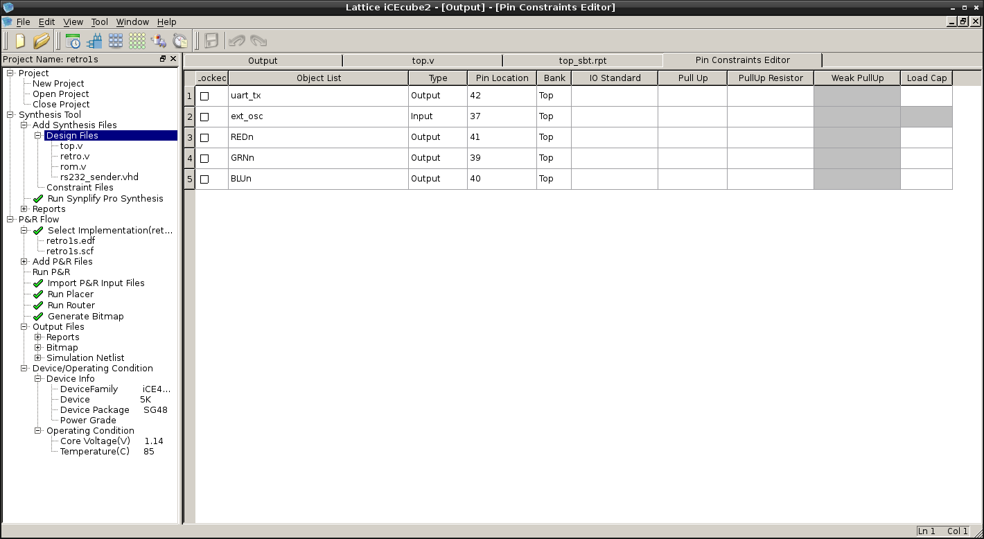
12 MHz should be connected to pin 37 (7th pin from the left top) and pin 42 is TX:
![]()
This is top.v that connects everything together (RS232 sender puts CPU on hold every character while busy):
module top(ext_osc,uart_tx,REDn,BLUn,GRNn);
input wire ext_osc; // 12 MHz
output wire uart_tx;

output  wire        REDn;       // Red
output  wire        BLUn;       // Blue
output  wire        GRNn;       // Green

reg [27:0]  frequency_counter_i;

wire [15:0] address;
wire [7:0] data,dataout;
wire clk,wren,hold,res;

always @(posedge ext_osc) begin
    frequency_counter_i <= frequency_counter_i + 1'b1;
end

assign clk = ext_osc;//frequency_counter_i[22];

retro cpu (
.nres(1'b1),
.clk(clk),
.hold(hold),
.address(address),
.data_in(data),
.data_out(dataout),
.wren(wren)
);

//assign addrout = address;

assign res = (address==16'h0)?1'b1:1'b0;

// RS232 sender by Frank Buss:
// entity rs232_sender is
//    generic (
//    system_speed, -- clk_i speed, in hz
//    baudrate : integer); -- baudrate, in bps
//    port (
//    clk_i : in std_logic;
//    dat_i : in unsigned(7 downto 0);
//    rst_i : in std_logic;
//    stb_i : in std_logic;
//    tx    : out std_logic;
//    busy  : out std_logic);
//end entity rs232_sender;

rs232_sender #(12000000,115200) TX (
.clk_i (ext_osc),
.dat_i (dataout),
.rst_i (res),
.stb_i (wren),
.tx (uart_tx),
.busy (hold)
);

//rom #(10) prog (clk,address[9:0],data);

rom prog (address[7:0],data);

SB_RGBA_DRV RGB_DRIVER (
      .RGBLEDEN (1'b1),
      .RGB0PWM  (hold),//GREEN
      .RGB1PWM  (clk),//BLUE
      .RGB2PWM  (wren),//RED
      .CURREN   (1'b1),
      .RGB0     (GRNn),
      .RGB1     (BLUn),
      .RGB2     (REDn)
);
defparam RGB_DRIVER.RGB0_CURRENT = "0b000001";
defparam RGB_DRIVER.RGB1_CURRENT = "0b000001";
defparam RGB_DRIVER.RGB2_CURRENT = "0b000001";

endmodule
Serial output configured as 115,200 8N1 and it's printing this in terminal:
Hello RISC-V!
Hello RISC-V!
Hello RISC-V!
Hello RISC-V!
Hello RISC-V!
Hello RISC-V!
Hello RISC-V!
Hello RISC-V!
Hello RISC-V!
According to iCEcube2 output, soft CPU here can run on up to almost 20 MHz:
#####################################################################
                     Clock Summary
=====================================================================
Number of clocks: 1
Clock: top|ext_osc | Frequency: 19.98 MHz | Target: 36.62 MHz
=====================================================================
                     End of Clock Summary
#####################################################################
But RISC-V program is still running from combinational ROM, so it is not yet a REAL thing with variables (other than registers), stack etc...
-
Video of the 1st test
12/25/2018 at 08:04 • 0 commentsNote: LEDs are inverted (because connected to power)
Now I need to add a serial interface instead of 8 LEDs to try more advanced programs :)
-
1st test on FPGA
12/13/2018 at 05:14 • 0 commentsFull project for iCEcube2 software configured for iCE40UP5K-SG48 FPGA device:
https://cdn.hackaday.io/files/1623976947993248/iCEcube2-retro1t.tar.xz
It's Retro-V v1.0.0 soft core with "Hello RISC-V!" test program ( provided by @Frank Buss ) that is stored as ROM:
/*
 Frank Buss: compile like this: riscv32-unknown-elf-gcc -O3 -nostdlib test1.c -o test1
 or
 riscv64-unknown-elf-gcc -march=rv32i -mabi=ilp32 -O3 -nostdlib test1.c -o test1
*/
void _start()
{
    volatile char* tx = (volatile char*) 0x40002000;
    const char* hello = "Hello RISC-V!\n";
    while (*hello) {
        *tx = *hello;
        hello++;
    }
}
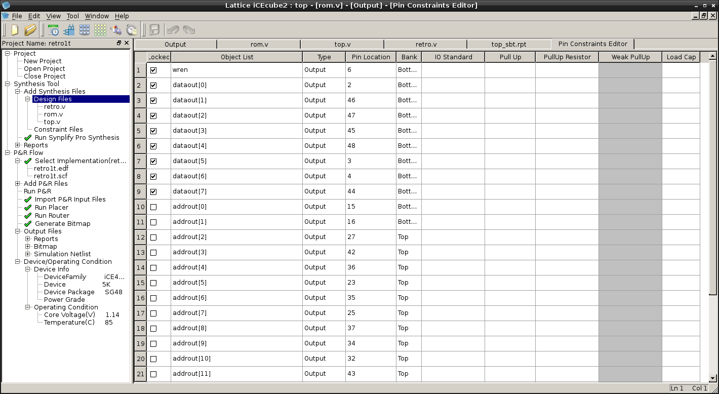
I locked data output 8-bit bus to bottom-left pins of UPduino:
![]()
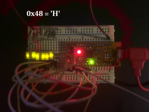
8 LEDs connected to them will "print" message character by character (LEDs show inverted bits):
![]()
So it prints:
01001000 = 0x48 = 'H'
01100101 = 0x65 = 'e'
01101100 = 0x6C = 'l'
01101100 = 0x6C = 'l'
01101111 = 0x6F = 'o'
00100000 = 0x20 = ' '
01010010 = 0x52 = 'R'
01001001 = 0x49 = 'I'
01010011 = 0x53 = 'S'
01000011 = 0x43 = 'C'
00101101 = 0x2D = '-'
01010110 = 0x56 = 'V'
00100001 = 0x21 = '!'
00001010 = 0x0A = '\n'
Source code is also uploaded to GitLab:
https://gitlab.com/shaos/retro-v/tree/master/FPGA/iCEcube2-test1
As you can see CPU clocked by 24th bit of the counter driven by high-speed oscillator, so it's like 16 millions times slower - in order to visually see what is going on there - blue blink is clock, red blink is write out (a character on 8 LEDs).
Design statistics: ------------------ FFs: 336 LUTs: 2211 RAMs: 4 IOBs: 25 GBs: 5 PLLs: 0 Warm Boots: 0 SPIs: 0 I2Cs: 0 HFOSCs: 1 LFOSCs: 0 RGBA_DRVs: 1 LEDDA_IPs: 0 DSPs: 0 SPRAMs: 0 FILTER_50NSs: 0 Logic Resource Utilization: --------------------------- Total Logic Cells: 2313/5280 Combinational Logic Cells: 1977 out of 5280 37.4432% Sequential Logic Cells: 336 out of 5280 6.36364% Logic Tiles: 342 out of 660 51.8182% Registers: Logic Registers: 336 out of 5280 6.36364% IO Registers: 0 out of 480 0 Block RAMs: 4 out of 30 13.3333% Warm Boots: 0 out of 1 0% SPIs: 0 out of 2 0% I2Cs: 0 out of 2 0% HFOSCs: 1 out of 1 100% LFOSCs: 0 out of 1 0% RGBA_DRVs: 1 out of 1 100% LEDDA_IPs: 0 out of 1 0% DSPs: 0 out of 8 0% SPRAMs: 0 out of 4 0% FILTER_50NSs: 0 out of 2 0% Pins: Input Pins: 0 out of 39 0% Output Pins: 25 out of 39 64.1026% InOut Pins: 0 out of 39 0% Global Buffers: 5 out of 8 62.5% PLLs: 0 out of 1 0% IO Bank Utilization: -------------------- Bank 3: 0 out of 0 0% Bank 1: 0 out of 0 0% Bank 0: 13 out of 17 76.4706% Bank 2: 12 out of 22 54.5455% -
Homebrew soft core
11/27/2018 at 09:07 • 0 commentsIn the last week I tried to create my own RISC-V soft core for this contest, but now contest is over and I was not able to achieve minimum requirements (100% passing RV32I compliance tests and ability to run RTOS Zephyr), but I've got really close - my current version is passing 54 out of 55 tests (through Verilator), including misaligned load/store exceptions and a number of control and status registers with atomic reading/writing (and all of that takes 3.4K LUTs) - see https://gitlab.com/shaos/retro-v
For now I made a decision that for this particular project exceptions and extra registers are overkill, so I rolled back a little and stayed with straightforward RISC-V implementation (only 2.2K LUTs of iCE40UP5K FPGA plus some BRAMs for 32 registers) that covers most of user level instructions and passing most relevant RV32I tests:
Check         I-ADD-01 ... OK
Check        I-ADDI-01 ... OK
Check         I-AND-01 ... OK
Check        I-ANDI-01 ... OK
Check       I-AUIPC-01 ... OK
Check         I-BEQ-01 ... OK
Check         I-BGE-01 ... OK
Check        I-BGEU-01 ... OK
Check         I-BLT-01 ... OK
Check        I-BLTU-01 ... OK
Check         I-BNE-01 ... OK
Check       I-CSRRC-01 ... FAIL
Check      I-CSRRCI-01 ... FAIL
Check       I-CSRRS-01 ... FAIL
Check      I-CSRRSI-01 ... FAIL
Check       I-CSRRW-01 ... FAIL
Check      I-CSRRWI-01 ... FAIL
Check I-DELAY_SLOTS-01 ... OK
Check      I-EBREAK-01 ... FAIL
Check       I-ECALL-01 ... FAIL
Check   I-ENDIANESS-01 ... OK
Check     I-FENCE.I-01 ... OK
Check             I-IO ... OK
Check         I-JAL-01 ... OK
Check        I-JALR-01 ... OK
Check          I-LB-01 ... OK
Check         I-LBU-01 ... OK
Check          I-LH-01 ... OK
Check         I-LHU-01 ... OK
Check         I-LUI-01 ... OK
Check          I-LW-01 ... OK
Check I-MISALIGN_JMP-01 ... FAIL
Check I-MISALIGN_LDST-01 ... FAIL
Check         I-NOP-01 ... OK
Check          I-OR-01 ... OK
Check         I-ORI-01 ... OK
Check     I-RF_size-01 ... OK
Check    I-RF_width-01 ... OK
Check       I-RF_x0-01 ... OK
Check          I-SB-01 ... OK
Check          I-SH-01 ... OK
Check         I-SLL-01 ... OK
Check        I-SLLI-01 ... OK
Check         I-SLT-01 ... OK
Check        I-SLTI-01 ... OK
Check       I-SLTIU-01 ... OK
Check        I-SLTU-01 ... OK
Check         I-SRA-01 ... OK
Check        I-SRAI-01 ... OK
Check         I-SRL-01 ... OK
Check        I-SRLI-01 ... OK
Check         I-SUB-01 ... OK
Check          I-SW-01 ... OK
Check         I-XOR-01 ... OK
Check        I-XORI-01 ... OK
--------------------------------
FAIL: 10/55
About actual design - my idea was to get a standalone 32-bit CPU kind of thing (small FPGA board with flashed in soft core) that will use EXTERNAL memory with 8-bit data bus to look like some kind of RETRO, but with GCC support. 8-bit data bus means that every 32-bit instruction will be loaded at least in 4 steps and I figured out how to decode and execute those instructions in the same time with loading. I called this design Retro-V and it's got version number 1.0.0. Now more details.
Retro-V soft core has 2-stage pipeline ( or more precisely 1.5-stage pipeline ; ) with 4 cycles per stage, so on average every instruction takes 4 cycles (with 40 MHz clock it will be 10 millions instructions per sec max):
- Cycle 1 - Fetch 1st byte of the instruction (lowest one that actually has opcode in it)
- Cycle 2 - Fetch 2nd byte of the instruction, determine destination register (rd) and check if instruction is valid
- Cycle 3 - Fetch 3rd byte of the instruction, read 1st argument from register file (if needed)
- Cycle 4 - Fetch 4th byte of the instruction (highest one), read 2nd argument from register file (if needed), decode immediate value (if needed)
- Cycle 5 (overlaps with Cycle 1 of the next instruction) - Execute complete instruction (with optional write back in case of branching)
- Cycle 6 (overlaps with Cycle 2 of the next instruction) - Write back to register file if destination register is not x0 (that is always 0)
As you can see Retro-V core reads from register file in cycles 3 and 4 and write to register file in cycles 1 and 2 (the same as 5 and 6 for 2nd stage of pipeline). The fact that reading and writing are always performed in different moments in time allows us to implement register file by block memory inside FPGA. Also it is obvious that this design doesn't have hazard problem if the same register is written in one instruction and we have read in the next because instruction reads 1st argument in cycle 3 and write back from previous instruction is already happened in previous cycle. In case of jump (JAL, JALR or BRANCH instructions) next instruction from pipeline alread performed 1st cycle, so it stops right there and next cycle is 1st one from new address effectively re-initing the pipeline (so branch penalty is only 1 cycle). In case of memory access (LOAD or STORE instructions) state machine stays in cycle 4 for a while (to load or store bytes from/to memory one by one wasting from 1 to 5 extra cycles) and next instruction in pipeline is kind of frozen between cycle 1 and cycle 2 in the same time.
If we count only "visible" cycles (from the beginning of one instructions to the beginning of the next one) then:
- JAL/JALR take 5 cycles always (because of jump)
- BEQ/BNE/BLT/BGE/BLTU/BGEU take 4 cycles if condition is false (no jump) or 5 cycles if true
- LB/LBU take 5 cycles (because of 1 extra cycle to read 1 byte from memory)
- LH/LHU take 6 cycles (because of 2 extra cycles to read 2 bytes from memory)
- LW takes 8 cycles (because of 4 extra cycles to read 4 bytes from memory)
- SB takes 6 cycles (because of 1 extra cycle to write 1 byte to memory and 1 preparational cycle)
- SH takes 7 cycles (because of 2 extra cycles to write 2 bytes to memory and 1 preparational cycle)
- SW takes 9 cycles (because of 4 extra cycles to write 4 bytes to memory and 1 preparational cycle)
- Everything else takes 4 cycles (plus 2 hidden cycles on the 2nd stage of pipeline)
Address bus is 16-bit wide (eventhough internally it's still 32-bit), so external memory could be up to 64KB (technically speaking it's configurable, so if FPGA has extra signal lines then address bus could be wider - up to all possible 32 bits).
-
Initial notes
11/20/2018 at 02:29 • 0 commentsRV32I[MA] emulator with ELF support (RV32M and RV32A are optional)
https://gitlab.com/nedopc/npc5/blob/master/emu-rv32i.c
gcc -O3 -Wall -lelf emu-rv32i.c -o emu-rv32iPassed RV32I compliance tests from https://github.com/riscv/riscv-compliance
make RISCV_TARGET=spike RISCV_DEVICE=rv32i TARGET_SIM=/full/path/emulator variantRunning simple code:
riscv32-unknown-elf-gcc -O3 -nostdlib test1.c -o test1
or
riscv64-unknown-elf-gcc -march=rv32i -mabi=ilp32 -O3 -nostdlib test1.c -o test1
then
./emu-rv32i test1
Hello RISC-V!
How to build RISC-V toolchain
https://riscv.org/software-tools/risc-v-gnu-compiler-toolchain/
Latest one is GCC 8.2.0
64-bit universal version (riscv64-unknown-elf-* unsuitable for Zephyr):
./configure --prefix=/opt/riscv

make
32-bit version (riscv32-unknown-elf-* suitable for Zephyr):
./configure --prefix=/opt/riscv32  --with-arch=rv32gc --with-abi=ilp32

make
RTOS Zephyr v1.13.0
https://github.com/zephyrproject-rtos/zephyr/releases/tag/zephyr-v1.13.0
It requires newer versions of CMake and DTC than my Debian had and also you need to do couple modifications for GCC 8.2.0:
1) lib/libc/minimal/include/sys/types.h:
change
#elif defined(__riscv__)
to
#elif defined(__riscv)
2) add to the end of zephyr-env.sh:
export ZEPHYR_TOOLCHAIN_VARIANT=cross-compile
export CROSS_COMPILE=/opt/riscv32/bin/riscv32-unknown-elf-
Zephyr example:
cd zephyr
source zephyr-env.sh
cd samples/synchronization
mkdir build && cd build
cmake -GNinja -DBOARD=qemu_riscv32 ..
ninja
emu-rv32i zephyr/zephyr.elf
Thanks to @Frank Buss for source code of emulator and howtos!
 SHAOS
SHAOS

