 Alex
Alex-
1Telegraph. Theory.
If you just turn on the transmitter (generator) at a certain frequency, it will not transmit any useful information. To transmit information, the radio signal must to be modulated. There are many different kinds of modulation.
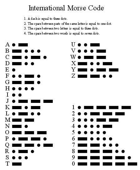
In HAM-radio practice, the simplest mode of communication is Telegraph (CW). Telegraph is a unique type of communication. Telegraph can be considered the first digital form of communication. However, a trained person is able to decode this digital signal by ear. Now to decode the Telegraph signal can be used decoder software. But the human ear is still considered to be the most accurate instrument for receiving a Telegraph signal. And also the telegraph is one of the most "long-range" types of communication. Due to the transmission at one frequency and low transmission speed, all signal energy is concentrated on one frequency, it has a positive effect on the transmission distance. Narrowband filters can be used for reception. A Telegraph signal consists of dots and dashes. Each character in the Telegraph alphabet is a combination of dots and dashes. The most commonly used letters consist of fewer elements.
![]()
Dots and dashes are the facts of turning on the transmitter. In the intervals between the dots and the dash, the transmitter turns off, the signal is not transmitted to the air. There are rules by which the dash must have a duration equal to three dots. The space between dots or dashes in one character must be equal to the duration of one dot. The space between the letters in one word must be three dots. The space between words must be at least seven dots.
If we connect a short-length wire (as an antenna) to the FPGA pin and send a clock signal to this pin, we will be able to receive this signal as an unmodulated carrier frequency. Turning on or off the signal to the antenna, we will modulate the carrier. And forming the correct time intervals for dots and dashes, we will form a Telegraph radio signal.
-
2Telegraph signal generation
To form time intervals in fractions of a second, we need to divide the clock signal. In my case, the frequency of the clock generator is equal to 25175000 Hz. I decided to take a 23 bit binary counter. The frequency obtained as a result will be equal to:
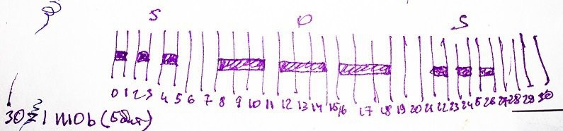
the counter is 2^22 = 4194304 (steps)
clock frequency 25175000 Hz
result frequency 25175000 / 4194304 = 6 Hz
The resulting frequency of 6 Hz is sufficient to form a single dot interval. Now let's try to form something very simple. For example, SOS signal: three dots, three dashes and three dots. Draw a time diagram:
![]()
From the diagram we can see that we need 30 steps. 30(dec) = 11110(bin). That's 5 bit's. That is, we add another 5 bits to the 22 bits of the counter. And we get 27 bits.
Now the logic is very simple (because complex logic we can not put in such a small FPGA): when the value of the counter is equal to 0, 2, 4, 8, 9, 10... (and forth on diagram) we are set 1, otherwise we set 0. This signal (CW) can already be output from the FPGA and controlled, for example, by flashing the led. And to modulate the radio signal, we will output the clock signal to the output only if the value of the CW signal is equal 1.module epm7064_test(clk, out_lf, out_rf); input wire clk; // clock input output wire out_lf; // low frequency cw output output wire out_rf; // modulated radio frequency cw output reg [27:0] cnt; initial cnt <= 28'd0; always @(posedge clk) cnt <= cnt + 1'b1; // 5 higth bits of the counter for generate symbols wire [4:0] hi_bits = cnt[26:26-4]; wire cw = (hi_bits == 5'd0) || (hi_bits == 5'd2) || (hi_bits == 5'd4) || (hi_bits == 5'd8) || (hi_bits == 5'd9) || (hi_bits == 5'd10) || (hi_bits == 5'd12) || (hi_bits == 5'd13) || (hi_bits == 5'd14) || (hi_bits == 5'd16) || (hi_bits == 5'd17) || (hi_bits == 5'd18) || (hi_bits == 5'd22) || (hi_bits == 5'd24) || (hi_bits == 5'd26); assign out_lf = cw; assign out_rf = cw & clk; endmoduleThat's all, it's time to turn on the receiver!
-
3Receive signal from our transmitter
Unfortunately, we cannot use a standard radio receiver to receive our transmitter. First, because of the frequency bands-the frequency of the transmitter is outside the known broadcast bands. Second, because of the type of modulation used. The broadcast radio receiver receives in the mode of amplitude modulation (AM). If you receive a Telegraph signal to the AM receiver, when the CW signal is not, the receiver will receive the air noise, and when there is a carrier, the receiver will be quiet (because the carrier is not modulated by amplitude). As a result, the AM receiver will make noise, interrupted by silence at the dots and dashes.
What is the receiver suitable for the reception of the Telegraph? To receive a Telegraph, you need a single-band receiver. When I chose the frequency of the transmitter, I cheated a bit. I have a USB SDR receiver, the lower limit of reception is 24 MHz, so the frequency of the generator I chose taking into account that the signal can be taken to this receiver. This receiver can be bought on ebay/aliexpress is very cheap. Search for words R820T2. As a program for receiving I am using the SDRSharp.
-
4Modify the transmitter to receive it on the AM receiver
After some thought, I remembered that I have a short-wave receiver. Reception frequency 530 — 1600 KHz AM. As a rule, this radio range is in every car radio. But we have build the receiver on this range with his son (from the leanring kit).
In order to get the carrier frequency in the frequency range of this receiver, we need to divide the clock frequency. If we take individual bits from our counter, we will get the values of the clock generator divided by the power of two (CLK div 2^N where N-bit number). For example, the 4th bit is divide clock by 16 and the result is 1573 KHz. I chose the 5th bit and the frequency = 786 KHz (because the Chinese variable capacitor was slightly defective, and does not cover the entire frequency range).
Now we need to make the amplitude modulation of the radio signal. In our case, it's easy to do — we have a Telegraph signal, so it's enough to interrupt the carrier frequency with an audio frequency. But for the reception on the AM receiver (for work of the amplitude detector in the receiver) will be enough. Choose bits from the counter-divider to get the frequency we can hear. This is the 14th bit, which is equivalent to dividing by 16384. The result is a frequency = 1536 Hz. This frequency can be heard by a human, and it is in the range of frequencies that the AM receiver is able to reproduce.
The text of the module on Verilog need a little changes:
wire audio = cnt[13]; // 14th bit - 1536 Hz - audio tone freq
wire rf    = cnt[ 4]; //  5th bit - ~786 KHz - sw-radio freq

assign out_rf = cw & rf & audio;
And we got amplitude telegraphy!
FPGA Frankenstein as CW Transmitter
Radio telegraph(cw) transmitter based on the Frankenstein FPGA evaluation board
Discussions
Become a Hackaday.io Member
Create an account to leave a comment. Already have an account? Log In.