 Matthew Peverill
-
Testing Matrix Input
02/17/2020 at 14:34 • 0 commentsSo in my new board I wanted to reduce the number of MCP chips used, since those use up board space and board space is $$. If you don't know what a diode matrix is, basically it's a multiplexing strategy (a way to get lots of inputs on fewer pins) and it's been better written up than I possibly could. Here are some resources:
- The best guide on diode input matrices was a post by komar about making a keyboard.
- Hackaday made a post on economic multiplexing strategies.
- arjhun maintains a script to generate a diode keyboard matrix schematic in Kicad.
Guides like these tend to have some interpretation room, however. Notably, I wasn't sure where to put the pull-up resistors. Boards are expensive and you never want to print one unless you know the wiring is right, so here is a breadboard test.
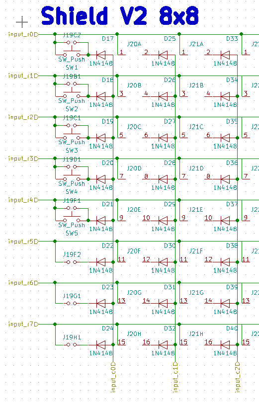
Schematic (from my controller):
pt 1:
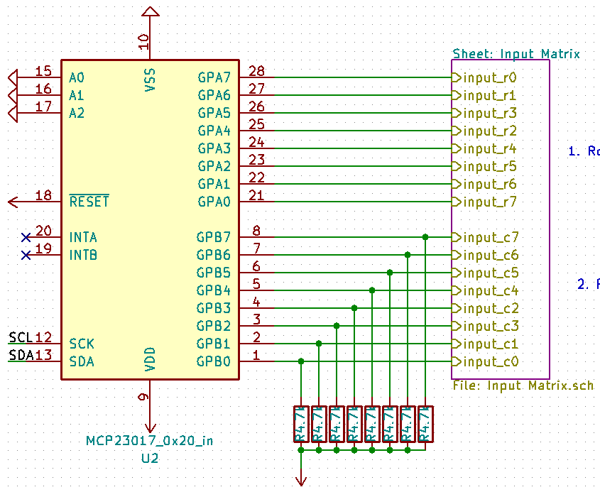
And the parent sheet:
So to translate: Rows are plugged in to GPIOA. We set the row pin to be read to low (the rest to high), then we read the column (GPIOB). GPIOB pins are pulled high.
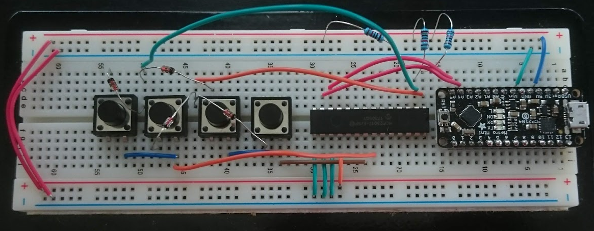
Here's a breadboard with four microswitches hooked up in a matrix (using my adafruit metro mini):
(remember: black stripe goes toward the pointy end in the schematic)
And here is a test sketch:
#include <Wire.h>
  const byte mcp_address=0x20;      // I2C Address of MCP23017 Chip
  const byte IODIRA=0x00;
  const byte GPIOA=0x12;            // Register Address of Port A
  const byte GPIOB=0x13;            // Register Address of Port B
  const byte qrows[] = {0b11111110,0b11111101,0b11111011};

void mux_Tx(int adr, int reg, byte data) {
  /* This function will send data to a MCP23017 chip */
  Wire.beginTransmission(adr);     /* address the chip */
  Wire.write(reg);                 /* point to the register of choice */
  Wire.write(data);                /* send the data */
  Wire.endTransmission();          /* end the transmission */
}

void mux_Rx(int adr, int reg, int numbytes, byte *data) {
  /* This function will request n bytes of data from a MCP23017 chip */
  Wire.beginTransmission(adr);     /* address the chip */
  Wire.write(reg);                 /* point to the register of choice */
  Wire.endTransmission();          /* end the transmission */
  Wire.requestFrom(adr, numbytes); /* request the data */
  *data = Wire.read();
}

void printBin(int var) {
  for (unsigned int test = 0x80; test; test >>= 1) {
    Serial.print(var  & test ? '1' : '0');
  }
}

void setup() {
  Serial.begin(9600); // Initialize the serial port
  Wire.begin();
  mux_Tx(mcp_address, 0x00, 0x00);  /* MUX 0x23, IODIRA, Set all to output (0) */
}

void loop() {
  for (int row = 0; row < 3; row++) {
    byte buff=0;
    mux_Tx(mcp_address,GPIOA,qrows[row]);
    mux_Rx(mcp_address, 0x13,1,&buff);
    printBin(buff);
  }
  Serial.print("\n");
  delay(100);

}
(incidentally, I highly recommend aliasing your MCP23017 registers if you're using them this way).
This outputs three rows. You can see on line 3 where a button was depressed:
000001110000011100000111
000001110000011100000111
000001110000010100000111
000001110000010100000111
000001110000010100000111
000001110000010100000111
000001110000010100000111
000001110000011100000111
000001110000011100000111
000001110000011100000111
It works! Now I can print the board.
-
New Board Design!
02/13/2020 at 02:32 • 0 commentsFinished my new board design! My goals were to:
- Get everything on one board
- Space the switches so that they lined up with the lines on a half sized notecard
- Use an Itsy 32u4 as a microcontroller board instead of an arduino.
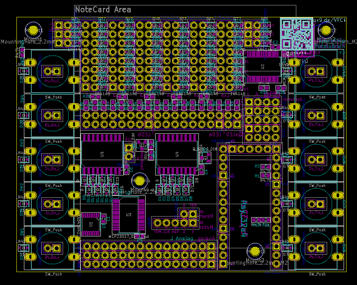
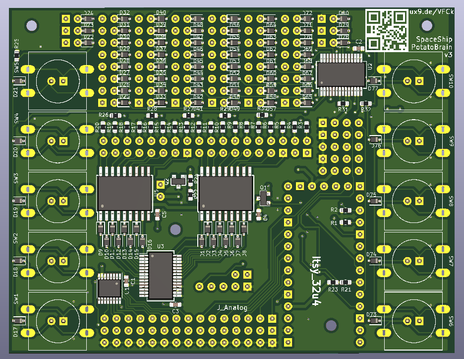
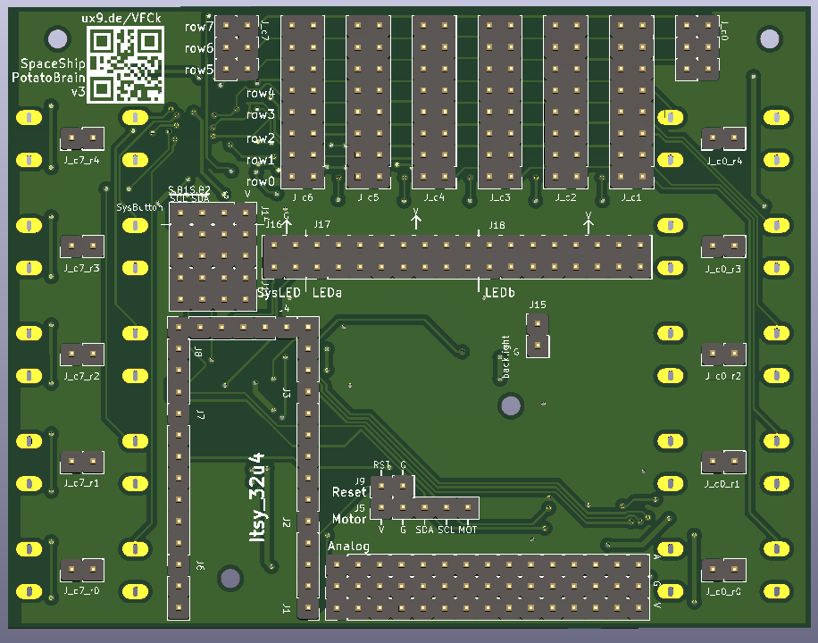
To do that, I switched almost everything to SMD and changed my input scheme to use one i/o expander hooked up to an 8x8 diode matrix instead of a bunch of i/o expanders. Here's a picture:
It ought to look like this:
-
Building a new Brain (picking transistors)
02/11/2020 at 20:24 • 0 commentsOk my dissertation is handed in! That means I have some time to work on this. I'm starting over on version 3 of the enclosure, because I don't want to spend time getting old designs working (the translation control in particular was not workable - more on that later). Because PCBs take the longest lead time, I'm working on that first. One of my notes was that I should switch to surface mount components and make one board.
Among other things, that means picking new transistors. I chose a 2n2219 and a 2n3906 for rev 1, following the fairly standard advice to try one of those and see what happens. Only one of those worked, and neither is available in surface mount, which means it's time to actually try and figure out how to pick these. There are two applications where I need a transistor, both related to lighting control. Here are my notes. Keep in mind I am not an engineer, and all of this is me trying to hack something together.
Backlight Control - Enhancement MOSFET
Ok application one is our strip lighting. I have about a third of a meter of LED strip lighting which I bought on aliexpress. According to their site, 1/3 of a meter will consume about .864 W at 5V (we might want to take that with a grain of salt). That comes out to .173 A of current, which we should round up to 200mA.
We need to pick between BJT and MOSFET. This can be done either way, but adafruit suggests MOSFET will use less current, so let's do that.
The Gate of the MOSFET hooks up to the 5V logic on the microcontroller. I'm using a PWM pin so that I can dim my lights.
Most posts of the type 'how do I pick a transistor' punt the question and say 'just use this one'. This was the most helpful guide I found, as it talks about why that is the typical advice AND tells you when it doesn't apply.
According to that page, we need a little more current than the typical application, so it may make sense to choose something carefully. Our dream MOSFET:
- Is 'enhancement type,' because we want current to flow when voltage is applied to the gate.
- Is 'logic level', i.e. Has a gate-source voltage such that, when the gate is at 0V (or near it) no current flows and when it is at 5V (or near it) 100% of the current flows.
- Can run at least 200mA, preferably more.
- Is small (but not so small I can't place it by hand.
- Switches fast enough to handle PWM.
Mouser has a page on MOSFETs. I set up filters to only show:
- Surface mount devices
- Channel Mode=Enhancement
- Continuous Drain Current > 200mA
- Vgs (gate-source Voltage): this is the hardest one, as there seems to be discrepancies in reporting. I selected single values between 2V and 4V and ranges between .5 and 4.5V.
I get 397 results, which I sorted in ascending price order and looked at the datasheet for the first.
I see that Drain-Source voltage is 500mA, definitely enough, and that maximum drain-source voltage is 30V. No problems there. I see that the device starts to turn on around 1 V, and is fully on at 3V - perfect. The package type is SOT-23, which is perfectly fine. Switching speed is hardest, but I think I can check it like this: Max PWM frequency on the 32u4 should be about 1kHz. According to this stack exchange post, We can sum the turn on time ( 7ns) and the turn off time (+30ns = 37ns), divide it by the percent time we are willing to spend turning off and on (so multiply by 100 for 1%), and get a period of 3700ns, which translates to about 270 kHz. So we should fine here.
LED Dimmer - Same
Ok our second application is as follows: our panel LEDs are driven by two ULN2803 darlington array chips. We don't have enough PWM for all the input pins, so instead we are using a common transistor to switch ground. We should still be able to use an enhancement MOSFET, which will be appropriate for the same reasons. We're going to drive up to 16 standard power LEDs. Each LED will probably take about 20mA, giving us 300 mA power draw. So we should be able to use the same MOSFET.
-
Things I've learned about analog human input devices.
11/24/2019 at 16:09 • 0 commentsLots of troubleshooting these past few weeks. Learned some good things and some dumb things:
1. Just say no to parts without datasheets (my throttle slider did not have a linear taper as advertised).
2. Don't test analog without ALL the pins being hooked up or grounded. Doing it piecemeal will just lead to confusion, because you won't be able to tell what's a floating input and what's an actual control.
3. Lots of people will tell you to use an ADC instead of a multiplexer. They are mostly talking about applications where more speed is required than we need for <20 human controlled inputs. The multiplexer can work just fine.
4. Joystick controllers typically don't have a very precise 'center'. So when you plug everything in without touching it, everything will have a slightly different 0 mark. This can be controlled in software.
5. Don't try to get fancy with hard wired switches if you need to switch inputs. Just do it in software - the switches will introduce spikes in the signal, and the wiring is a pain. (For my project at least) there are enough extra inputs to do this without trouble.
-
Mounting Gamepad Joysticks
11/12/2019 at 14:02 • 0 commentsMy camera controls work via some 'gamepad style' joysticks. These do not come with a built in mount and it is a little tricky to get them on a panel because the plastic joystick part needs to rotate freely. My solution was to get some breakout boards (like these boards from Sparkfun), drill some holes for the actual joysticks, and go from there. I ran in to problems immediately. First, I highly recommend using the laser (If you are using one) to drill the holes for the standoffs, because they need to be squared to the joystick. Second: the standoffs are sensitive, height-wise. If they are too short, the joystick will rub against the panel creating friction and sticking. If they are too long, the joystick won't have enough range of motion.
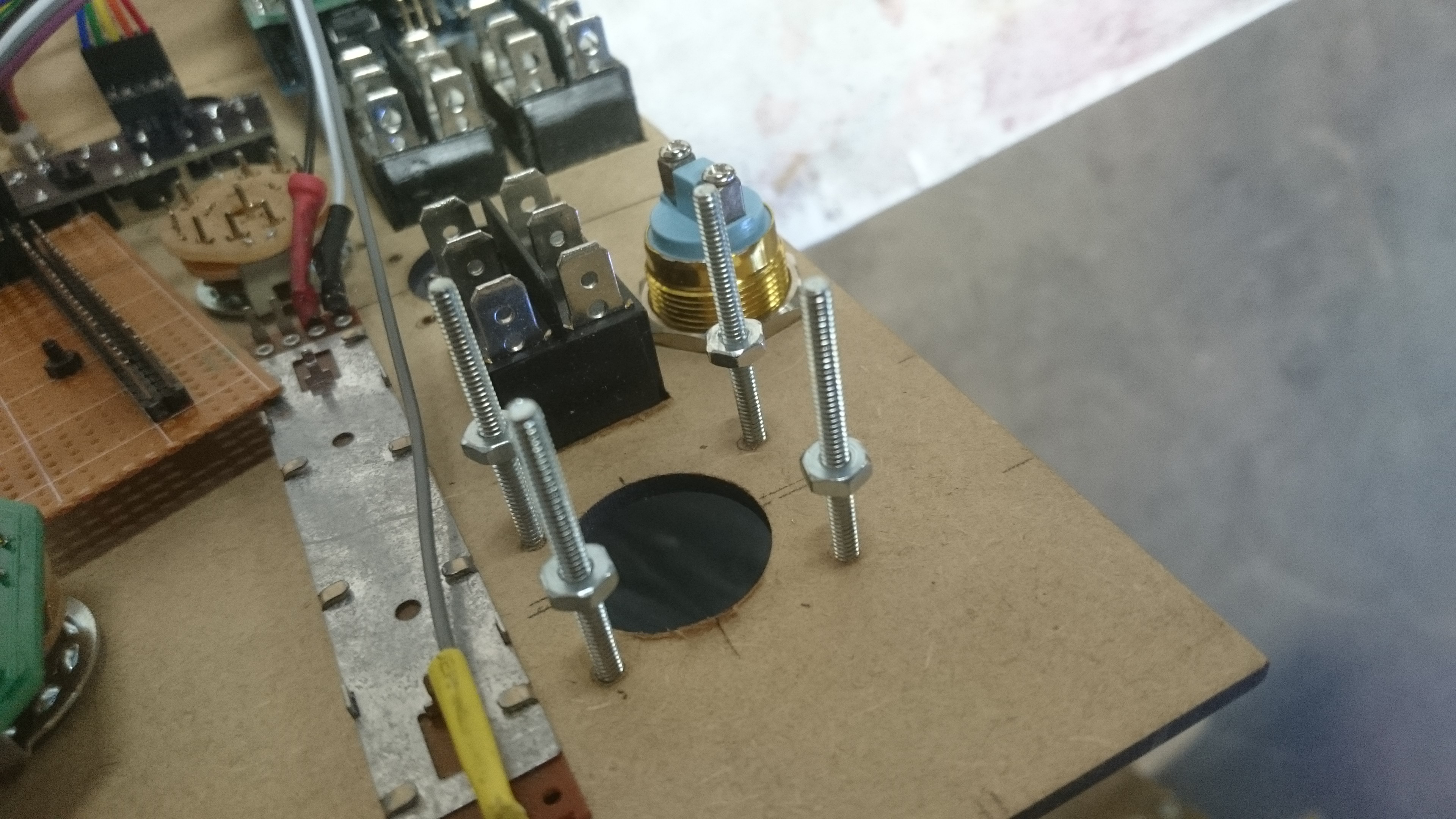
My solution was to get a couple of narrow bolts and a set of nuts and nylon washers:
![]()
This allows you to adjust the standoff height of the joystick until it is just able to move freely. Then you slip the standoff on top, and tighten another set of nuts on top. If doing it again, I'd also put nuts down by the panel, but I didn't have enough.
-
Wiring and Light Control
10/28/2019 at 12:49 • 0 commentsNow that the basic circuits are lined up it's time to start wiring. I wired up some of the LEDs and wrote a script to let them be controlled by buttons.
Only issues at this point are:
1. The light test button isn't working. This may also be a loose wire (I continue to have problem with the budget wires I bought - so not worth it).
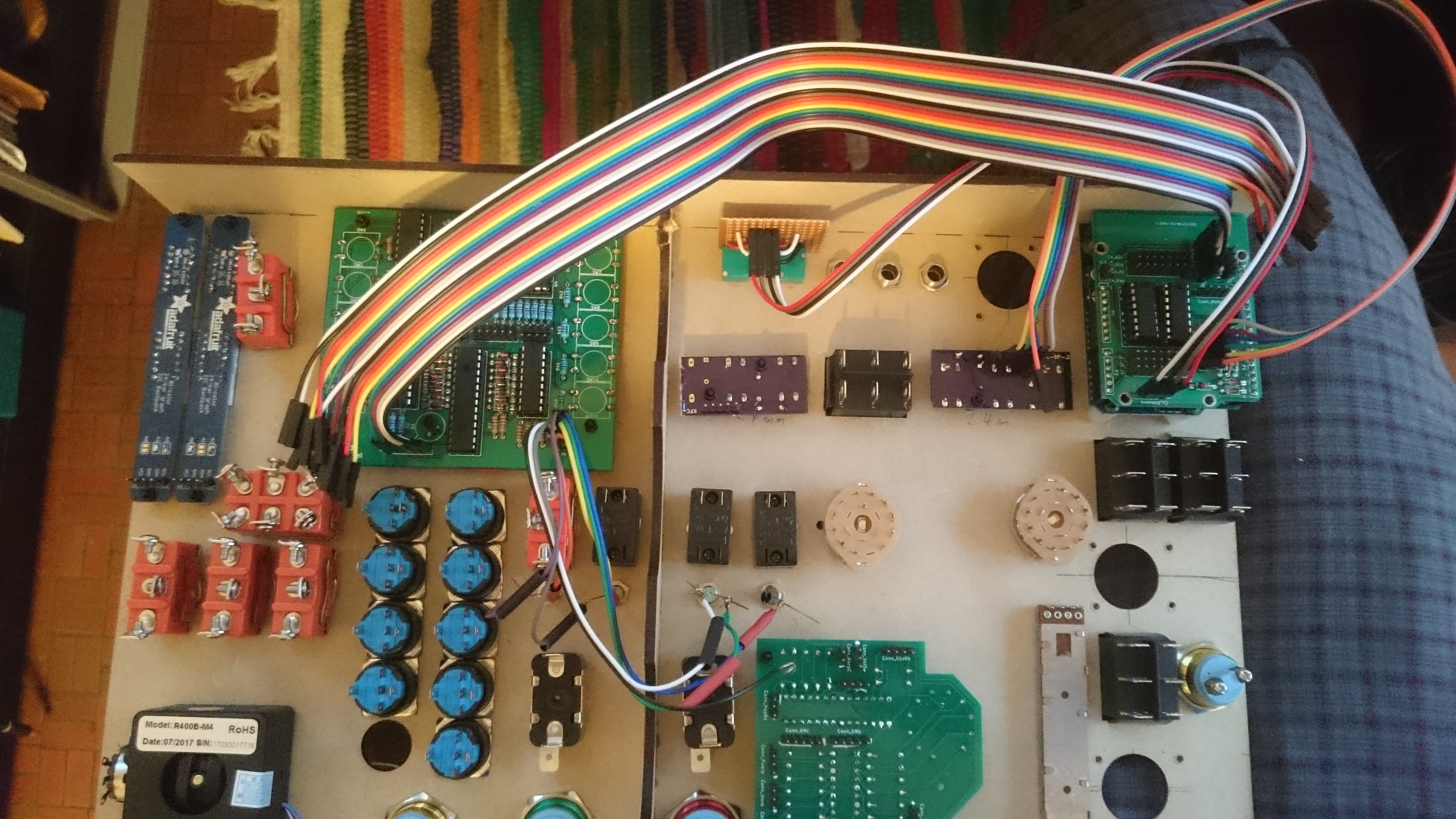
2. My wiring is a mess:
![]()
This level of chaos will become truly frightful extended to all the other connections I need to make for this build. Even worse because in later versions I want backlit controls, which will need me to keep the wires away from labels (or maybe I'll just need to rely on diffusion). It seems like the best bet would be to fasten wires to the panels somehow, but I'm not exactly sure how to do that (and it would be easier with thinner wires).
-
SAS Buttons
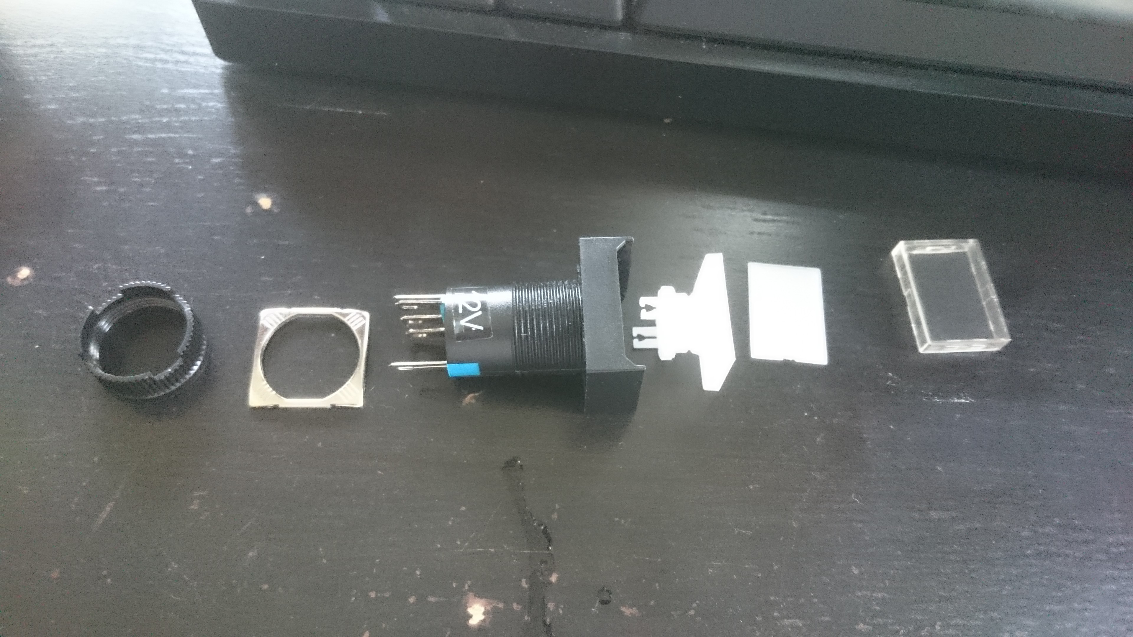
10/11/2019 at 14:34 • 0 commentsI have some lovely buttons from a vendor on aliexpress, but they are a bit generic. I want them to have nice labels on them. How to do this? Well first we have to take them apart. The easiest way to do this is to use a screwdriver to pry out the button cap - this is no problem, as they are not latched in permanently. The transparent part of the keycap can then be separated from the white part by pulling the shorter edge of the cap away from the filled part (again I used a screwdriver). Then the white part further separates in to a cap and a plunger:
![]()
Just a note that I did break one of my buttons doing this, so you may want to plan on having extras if you want to do the same. They are not expensive.
Ok so then we want to affix labels. I considered just drawing on the inside with sharpie, but that wasn't quite the aesthetic I'm going for. Instead, I decided to print on transparencies and insert those in to the key caps. Here's how I did it:
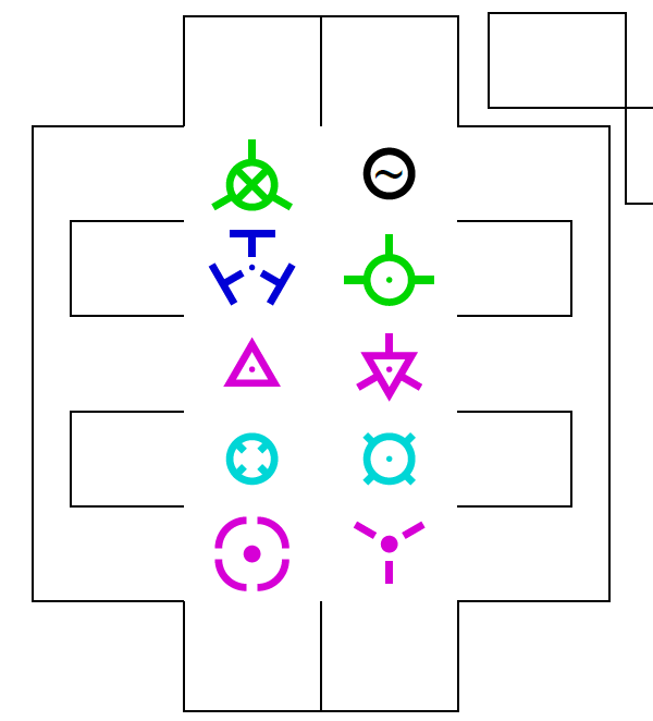
- I downloaded the SVG versions of the various SAS indicators from the kerbal wiki (credit XSize).
- I loaded them in to an 8.5 x 11" drawing in Inkscape and I made boxes the approximate size of the inside of the keycaps.
- I resized them to approximately fill the boxes.
- I made a new icon for stability assist by putting a tilde (~) in a circle.
- I used the arrange tools to center the symbols in their boxes
- Using snap to corners, I made lines outside the boundaries of the buttons as a cutting guide.
- I deleted the boxes around the buttons. This leaves you with an image that looks like this:
(I've posted the labels file on github).
I printed to pdf, and then I had it printed to transparencies at Fedex (which costs about $1.90 a sheet). Print extras (I did three).
I used an exacto knife to cut along the lines I drew out. I did not manage to do this very neatly, but it turned out totally fine. If you are exacting, I'd recommend thinking carefully about what order to cut in, as it will be difficult to cut to guidelines when your transparency pieces start coming loose.
Put the transparency inside the transparent keycap and reassemble.
![]()
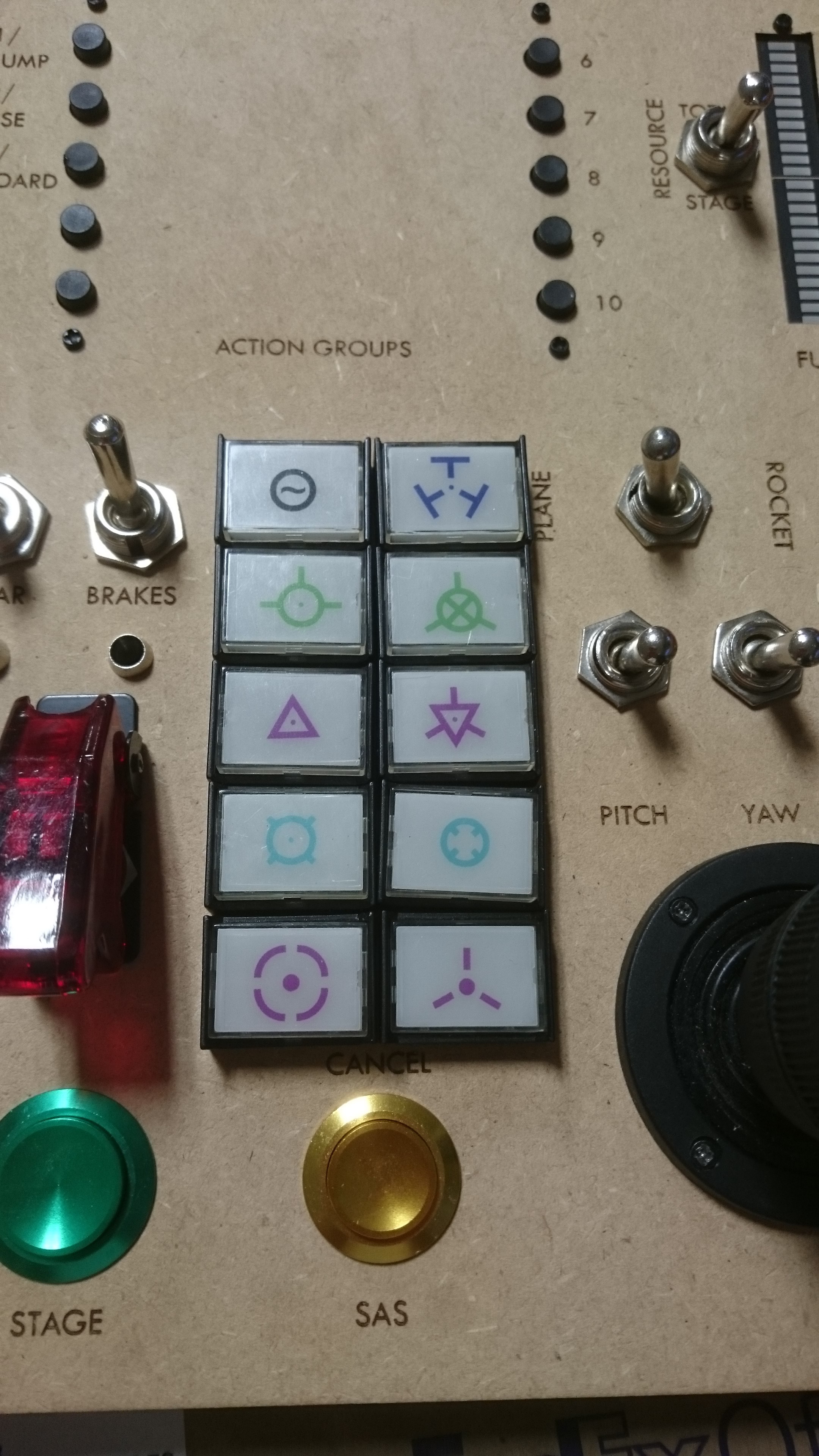
Make sure you put the keycaps in to the panel in the orientation and order you want.
Here's the finished product - pretty cool!
![]()
-
Testing On-Board Light Control (how to find dumb mistakes pt. 3)
10/05/2019 at 19:45 • 0 commentsSo a few logs ago I posted about developing an LED light circuit. It was fairly complicated, because we want a central dimmer control as well as a hardware light test button. I've been having some trouble getting the circuit (as built in to the action panel) working. As always, we are just going to have to isolate everything that can go wrong and break down the testing to isolated tests. So here is my troubleshooting process:
1. Is the action panel hooked up right? I hooked up the action panel to my breadboard and repeated the i2c input test. AND we have a winner: we got an i2c timeout.
When I first tried out the i2c, I realized that the power plane on my action button panel wasn't hooked up. When I tested, i sometimes needed to adjust it before I could get a good test. I tried out this connection with the multimeter and it looks to me like it's still not hooked up right. Probably this is because I tried to solder it on to the microswitch leads, which are a bit shaky because I had to bore out the holes to get them on the board. Instead I bridged the power across the +5V pins of the LED hookups and now it works fine:
2. Is the LED working? First I hook it up to voltage with a resistor, then to PWM straight off the arduino with the default 'fade' sketch: works fine.
3. OK now can I hook up my led to the action panel? No. But, if I ground the 'light test' pin then the light turns on. So the light test portion of the circuit appears to be working ok. Possibly the circuit is fine and this is a software issue?
4. What if I connect the corresonding pin on the ULN to high? That works fine! Ok this is almost certainly a software problem then - because the issue may be that the MCP pin isn't being set correctly.
4. Look at some example code. Ah-ha - I am writing to the wrong registers on the MCP23017 switch. I need to write to 0x12 and 0x13 just as if I were reading. Now it works!
-
Haptic Motor Control
10/02/2019 at 23:22 • 0 commentsI hooked up my motor control! This is a cool little breakout board for the DRV2605L haptic motor control chip. This thing is very powerful - I'm certain I could do more with it than I am. I tried out the demo, which plays effects from a library, but I realized that they don't give much control. What I really want is to control vibration on a continuous scale, so I can scale it with thrust and/or drag (not sure what would feel best).
How we do that mechanically is to put the chip in PWM mode, which scales vibration with PWM input (for testing, I controlled the PWM with a potentiometer). Initially, I ran in to an issue where vibration was strongest when PWM was at zero and 100%. I had to get deep in to the (long) datasheet to figure this out: this is default behavior for the chip in 'open loop mode', which (if I'm reading the sheet right) uses feedback from the motor to calibrate some of its features. I could put it in closed loop mode and have it respond more intuitively, but I'd have to know more about my motor (which I don't, because I scavenged it from an old xbox controller). Instead, this can be handled by scaling the output signal from 50-100% instead of 0-100% via the map command. Here's the relevant code:
outputValue = map(sensorValue, 0, 1023, 127, 255);
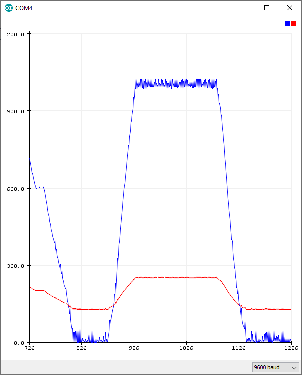
If we map outputValue and sensorValue to the plotter, they respond like this, with the vibration being zero when the red line is at minimum and maximum at maximum:
I also purchased a little USB in line amp meter so I can start figuring out power utilization. The difference in power consumption between minimum and maximum vibration is about .026A.
-
Analog Testing
08/24/2019 at 23:13 • 2 commentsOk today I'll be testing analog input. The shield has room for 20 analog inputs:
- 2 directly wired for dimmer control.
- 2 wired through 74HC4051 multiplexers.
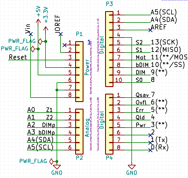
The relevant parts of the shield schematic are useful for this. Here is the pinout from the arduino:
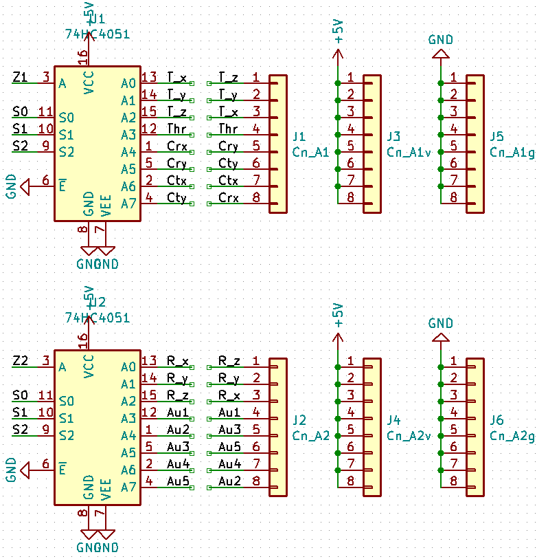
And here are the multiplexers:
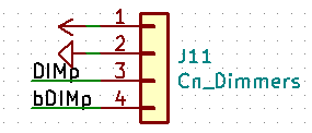
And here are the direct wires:
Test code is heavily cribbed from Sparkfun's tutorials. I've modified them to: print the additional analog inputs. Read and print both multiplexers every time pin select happens.
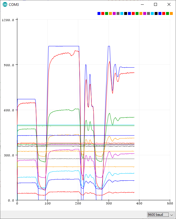
/******************************************************************************
Multiple Analog Mux and hardcoded input test.
Based on: "SparkFun Multiplexer Analog Input Example
Jim Lindblom @ SparkFun Electronics
August 15, 2016
https://github.com/sparkfun/74HC4051_8-Channel_Mux_Breakout"


******************************************************************************/
/////////////////////
// Pin Definitions //
/////////////////////
const int selectPins[3] = {8, 12, 13}; // S0, S1, S2
const int zInputa = A0; // Connect common (Z) to A0 (analog input)
const int zInputb = A1; // Connect common (Z) to A0 (analog input)
const int DIMp = A2;
const int bDIMp = A3;
void setup()
{
  Serial.begin(9600); // Initialize the serial port
  // Set up the select pins as outputs:
  for (int i=0; i<3; i++)
  {
    pinMode(selectPins[i], OUTPUT);
    digitalWrite(selectPins[i], HIGH);
  }
  pinMode(zInputa, INPUT); // Set up Z as an input
  pinMode(zInputb, INPUT);
  pinMode(DIMp, INPUT);
  pinMode(bDIMp, INPUT);

  // Print the header:
//  Serial.println("Y0\tY1\tY2\tY3\tY4\tY5\tY6\tY7");
//  Serial.println("---\t---\t---\t---\t---\t---\t---\t---");
}

// The selectMuxPin function sets the S0, S1, and S2 pins
// accordingly, given a pin from 0-7.
void selectAMuxPin(byte pin)
{
  for (int i=0; i<3; i++)
  {
    if (pin & (1<<i))
      digitalWrite(selectPins[i], HIGH);
    else
      digitalWrite(selectPins[i], LOW);
  }
}

void loop()
{
  // Loop through the hard wired dimmers
  Serial.print(String(analogRead(DIMp))+" ");
  Serial.print(String(analogRead(bDIMp))+" ");
  // Loop through all eight pins.
  for (byte pin=0; pin<=8; pin++)
  {
    selectAMuxPin(pin); // Select one at a time
    int inputValuea = analogRead(zInputa); // and read Z1
    int inputValueb = analogRead(zInputb); // and read Z2
    Serial.print(String(inputValuea) + " " + String(inputValueb) + " ");
  }
  Serial.println();
}
Unfortunately, when I first turned on the Arduino's serial plotter, this is what I get when I turn one of my throttle potentiometers (nothing else does anything):
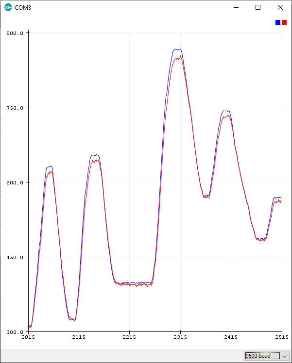
Ok first let's cut out everything but the dimmer pots (A2-A3):
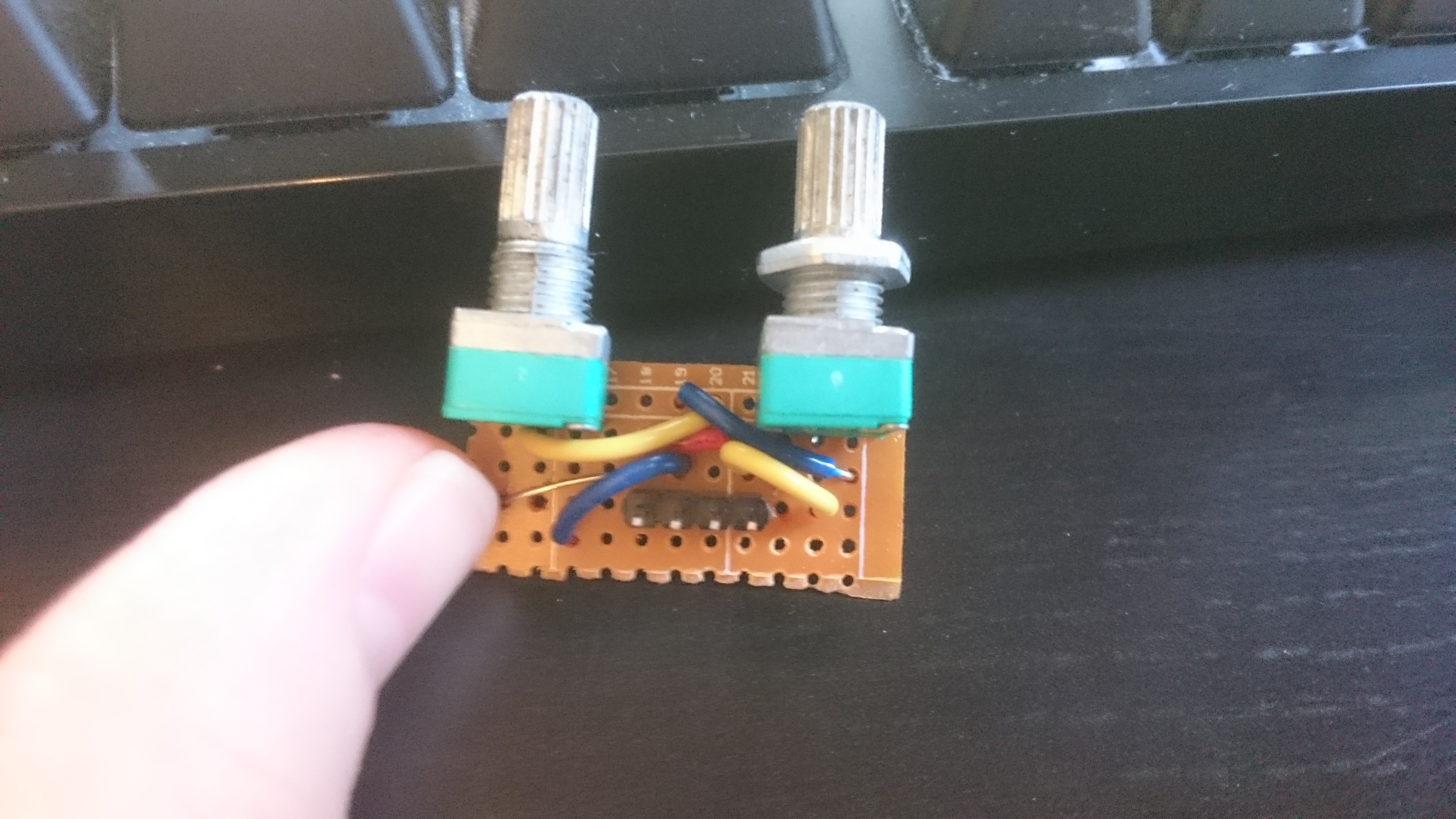
These should not be in sync! Ok so now we need to know if there is an issue with the shield or with the jury-rigged protoboard I have the pots hooked up to. I plugged said board in to the other arduino and got exactly the same result. So probably something dodgy with the protoboard, which is not surprising because it's a mess.
![]()
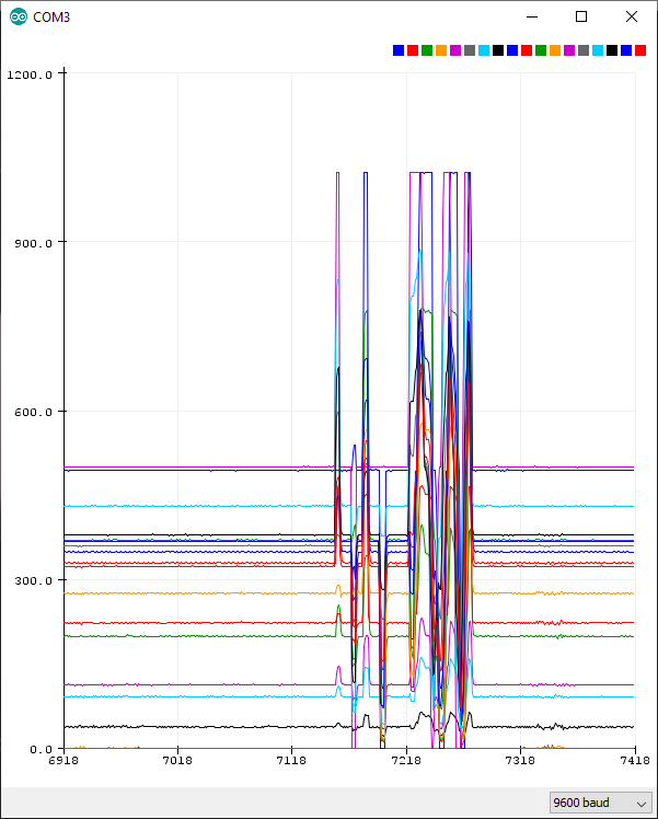
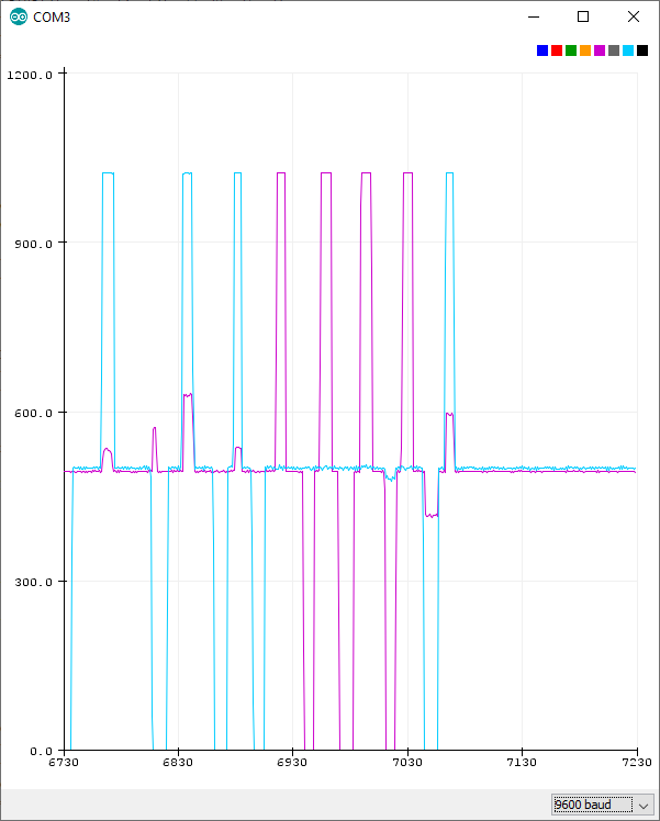
Let's not do this again, ok? OK, but what about the multiplexers? Even without the dimmer pots plugged in, we get a horrible mess:
Only one joystick seems to do anything, and what it does is move all the analog pins at once. What's happening here is that the other analog pins are just open (because I only plugged in the 2 pins from the joystick). If you ground them, then suddenly the output looks much more sensible:
Good news! The circuit on the shield seems to work just fine.
Kerbal Spaceship Potato
This is an input focused control panel for Kerbal Space Program.
 (I've posted the
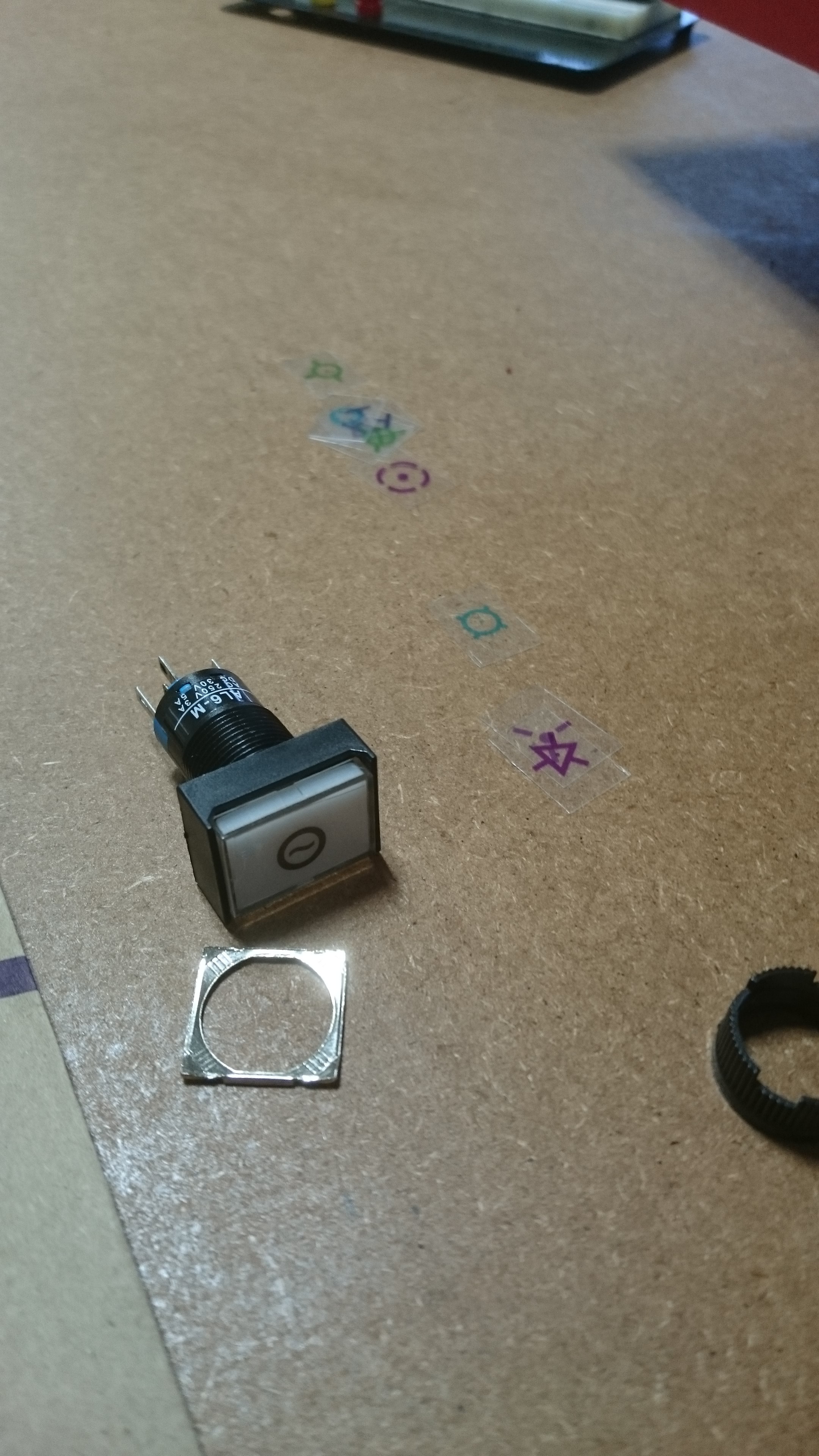