Close
0%
0%

Kerbal Spaceship Potato

This is an input focused control panel for Kerbal Space Program.

Similar projects worth following

This is my dream controller for Kerbal Space Program. It is a hobby project, and I am a PhD student, so expect slow progress.

My focus is on quality inputs. I don't expect to be able to fly with just the panel, and I'd rather be looking at the screen anyway (also I am already stretching my pin allotment).

I've completed a few prototypes of graduated complexity while I got a feel for the design. I made a draft version of the elecronics, which had some flaws, and decided to re-do them using a smaller microcontroller (the adafruit Itsy 32u4) and a single board design. This should be the final version, and it's currently in development.

Code and electronics design both heavily based on https://github.com/PeteWasEre/Very-Kerbal-Kontroller-V2

  • Wires + More Wires

    Matthew Peverill02/23/2021 at 01:59 0 comments

    Still alive! I've started wiring -- all the analog devices are plugged in and all of them worked right off the bat -- score one for iterative design! I'm not totally satisfied with the wiring scheme: I'm using pre-crimped wires going in to female header blocks, which attach to the header pins on the board. It's hard to optimize the length, so some wires end up too long and others have more tension than I'd like. It's going to be hard to make them neat. I'm pretty sure the 'optimal' solution is to crimp my own wires, but I'm probably going to just roll with it at this point. 

  • Video Tour Pt. 1

    Matthew Peverill12/15/2020 at 01:17 0 comments

    Some progress in the last few months. Here's a little tour of what I have so far!

  • Motherboard is complete!

    Matthew Peverill07/27/2020 at 14:53 0 comments

    Ok, at long last, I can successfully register every button on the matrix, control every led, read from every analog device, and talk to every i2c device. This took some doing. Once the dead short was resolved, testing revealed a number of issues. Two of the rows and two of the columns were switched in the output. A number of the button switches didn't register, and button presses on c5 and c6 seemed to produce somewhat random button presses elsewhere on the matrix. The analog inputs from the 74HC4051 didn't work at all, and 3 of the LED outputs from LED bank a didn't drive. I inspected the thing in the microscope and it looked like a lot of my pins were lifted on U1 and U2, so I replaced them. This took care of the analog issues. I also replaced the diodes in the switch matrix for buttons that weren't working. The issue with c5 was with the pull up resistor: it was soldered fine, but I think the trace was broken somewhere (probably at a via - this is most likely because I've worked on the board so much there may be some delamination). I repaired this with a wire. The led issues were resolved by resoldering the relevant diodes and pins on the i/o expander (pro-tip: make sure you check both of these separately: I replaced one diode like 4 times before I realized it wasn't the issue, and had to put in a wire bridge because the pad lifted).

    So now the board works and I can actually assemble this sucker! My big lesson on board assembly is that you should take NO SHORTCUTS when pasting and reflowing the board. I didn't check all my footprints to my devices on paper (which also means I didn't check I had everything I needed), I didn't buy new paste, and I used a plastic rather than steel stencil. This saved me $30 on parts and 2-3 hours in assembly, and cost me more than that in replacements and dozens of hours troubleshooting. If I had a time machine I'd go back and do it right at the paste stage so I didn't have to do so much with the soldering iron.

    There are also a few design issues on the board that I'll fix in v3 (which I won't build, but just in case anyone else needs to):

    1. Pin A7 can't be used to drive a PWM LED (as it is currently laid out to do). I should be able to fix this by putting in a transistor hooked up to the dimmer circuit.
    2. I made each part of the board as tightly grouped as possible. There are a few places (especially the diodes by the ULN chips and microswitches and the components around the matrix chip) where I could space out the components a bit more to ease hand soldering if it were necessary. I'd use a different diode footprint if possible, but I'm not sure there's anything better). I'd love to have bigger ICs, but I don't think there is room on the board for them. 
    3. Two rows and two columns are switched in the schematic relative to the I/O expanders registers, which makes the output less predictable. This is an easy fix on the schematic and switching the wiring by the IC. 

    Panel assembly is 80% done: stay tuned for good pictures with that update!

  • Software Design Pt. 1

    Matthew Peverill06/23/2020 at 17:22 0 comments

    With the board almost up and running (and a vacation coming up with little access to the shop), I'm starting to think more intensely about software design. For those of you who haven't done this research, there are at least 5 basic approaches, with the additional possibility of combining them. Unfortunately it can be hard to get concrete information about both the capabilities of these solutions (because so many people modify them; e.g. KSPSerialIO has 38 forks on github), and their performance (because it varies with quality and complexity of implementation). The result is that I've ended up trawling the forums for definite guidance and ended up with a lot of hearsay. 

    So before I actually write any code, it's worth laying out in detail what capabilities I'll need so I can approach implementation in a structured way (knowing that any of these are going to take a LONG time to implement, so better not resort to trial and error.


    Features 

    Here's a table of our features and which solutions can accomplish them (at least, in principal). This is just what I need from the plugin / interface with KSP: some controls are managed solely in code I'll write, like throttle limiting. Also: these are all complex projects, so take these with a grain of salt:

    What dokRPC?Joystick Emulation?KerbalSimpit?
    Quick Save/Load
    Switch Vessel?
    Switch Map Target?
    Toggle Map
    Stage+Abort
    Switch SAS Mode❌*
    Throttle
    Increment Warp and P. Warp
    2 Custom Axis Groups❌ (maybe through wheel steer/throttle axis)❌ (maybe through wheel steer/throttle axis)
    3 Axis Translation Control
    RCS/Light/Gear/Brake Groups
    10 Action Group Buttons
    Rotate / Pan / Zoom Camera
    Select Camera Mode❌*
    Select velocity display mode
    (target/orbit/surface)
    ❌*
    3 Axis Attitude Control
    Output Fuel/Electric/Xenon level - Stage and Vessel
    Output Change in Resources ???
    Output RCS, Gear, Brakes status
    Output Current Selected SAS mode
    Output Vessel Supported SAS modes
    (maybe with part detection)
    Output Vessel Type Info (maybe)

    *: a mod on top of joystick control might accomplish this.

    I didn't consider KSPSerialIO, as it's a bit harder to find documentation for (and, as I've said, has been extensively forked). It does have some cool features (for example, it can set the navball speed display mode).


    Performance

    Features are good, but performance is everything. This is meant to be a HID experience, and people can detect imput lags as small as 1ms, so the system needs to be high performing. 

    Arduino to python is, in my view, unlikely to be a bottleneck. With no compression, we are transmitting no more than 64 bits (8 bytes) of binary switch data, 13 axes (another 13 bytes at 256 resolution), and are receiving 2 bytes of LED data, and about 6 of miscellaneous other information. That's 29 bytes per transaction, call it 50 with fudge factor. If we wrote the most inefficient system possible, that would mean we'd need to transmit 50kbytes p/second (or 50,000 baud) with 1000 transactions p/s, which is well within the capabilities of our chip. We're gonna figure out a way to get that done. Performance issues really come in when we talk about communicating to the game.

    At first glance at the above, kRPC is a no brainer. The Krpc documentation describe that the mod makes updates every game tick, and you can set it up to either yoke KSP performance to the mod OR minimize the number of server calls it can make per second to minimize lag. There is a wait time where Krpc is listening between calls, so with complexity lag will increase (I imagine this is especially true for inputs like analog axes, which are more likely to be constantly updated). That matches the word on the street, which is that KRPC is laggy with controllers with a lot of complexity (which is understandable,...

    Read more »

  • The board is alive!

    Matthew Peverill06/20/2020 at 14:10 0 comments

    I finally fixed the short! After lots of reading about freeze spray, IR cameras, finger testing, etc, I finally followed the intimidating advice to hook up some current and use a multimeter to find where the smallest voltage drop was. In my case, this meant about 1.5 A of current hooked up to the VCC and Gnd Pins. Then, because I was pretty certain the short was below one of my ICs, I just measured the voltage across each corresponding capacitor. The MCP chip I set up to handle LEDs had the lowest voltage drop and when I popped it off the board, sure enough, there was a giant solder bridge below the chip out of sight. I fixed that, and now I can talk to my MC when it's plugged in to the shield! I'll be posting about my further debugging over the next few days/weeks.

    A quick soldering retrospective: like a lot of people, I was intimidated by switching to surface mounted from through hole devices. I agree with others I've read that this is a bit silly. Soldering smaller smd components is not a huge deal. In some cases it's easier. That said, I wish I had avoided .5mm pitch components when I could get away with it: they are much harder to trouble shoot and solder than the bigger surface mounted devices.

  • How to make a back-lit control panel on engraving acrylic.

    Matthew Peverill06/09/2020 at 16:59 0 comments

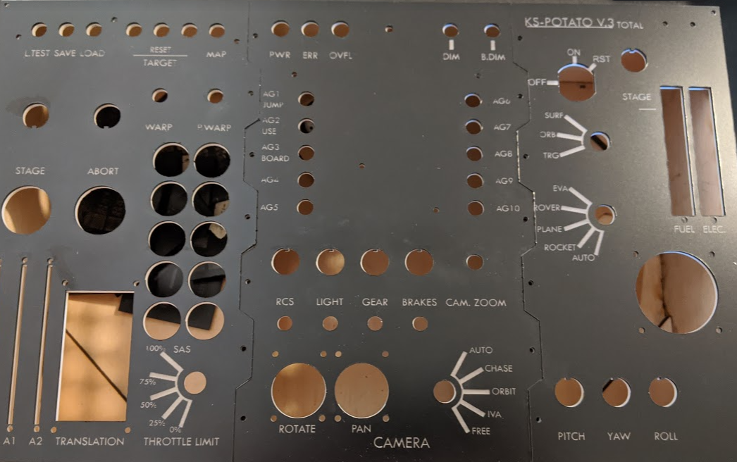
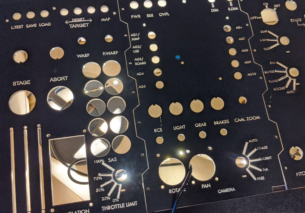
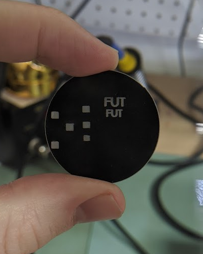
    So I wrote a bit last time about a naive approach to making this panel. Short story is, it didn't work very well. The medium length story is that I did a bunch of research, and it turns out this is a famously hard problem. I wouldn't recommend doing this unless you really want backlighting: the material is not cheap, you're going to need extra, and it is a ton of work finding the right settings. That said, I did manage to produce a finished product that looks pretty sweet eventually. There is a little bit of drop-out in some of the finer letters, and some surface marring, but basically this is more than good enough:

    It was, however, a pain in the butt. Long story and process after the break.


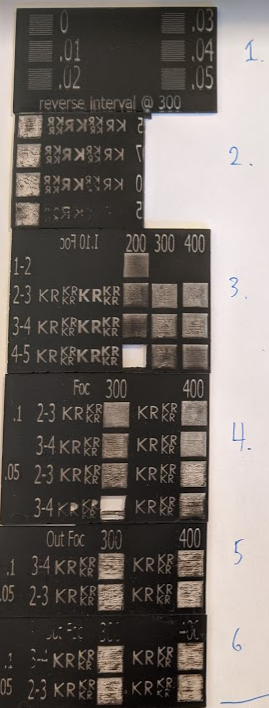
     Here are the swatches from day 1 of testing:

    1. is the reverse interval tuning@300 (I already did it at 400). This is a good idea if you want sharp text, because it syncs up the left and right swing so the laser is making clean vertical edges.

    2-6 are all testing various combinations of power, speed, and interval. In 3, power is 10-20, 20-30, 30-40, and speed is 200-400. 20-30 at 400 seemed to be the best result, but there is a lot of mess. I then tried to improve things by changing the interval to .05, that didn't help. I tried bringing the laser out of focus, but then the text lost definition. So I cut a panel at 300 speed at 45 or so (a little more power) and hoped for the best. The result is in my last post: there was a lot of mess in the engraving still. 

    So then I went back to the drawing board. There is a lot of advice about this, but by far the best source, and the one which helped me understand what was going on above, was this one from Mike at Trotec:

    My take away messages from this video were as follows:

    It's easy to interpret the mess, for example in the samples above, as evidence that power is too low. That's exactly wrong: what's happening is that the laser carves little furrows in to the surface, and they become filled with vaporized acrylic from the top layer, which messes up the contrast. The higher the power, the more vaporization, and the more mess in your cuts. Above, you can see that as I increase power there is actually more mess in the cuts: that's not the black cap layer, that's re-deposited vaporized acrylic.

    Instead, you want to use the lowest power you can which will go all the way through the top layer. So, looking above, 20-30 power at 400 mm/s is probably closest. Past that, the best way to avoid mess in your cuts is to defocus the laser. I did try that on day 1, actually, but by way too much and at too high a power. Mike defocuses 9 thou(sands of an inch). Tip number three is cleaning: You want to use mr. clean magic eraser to remove the ejecta (to use a kerbal-y term). This is extra good for us, because we don't have to worry about scratching up the back surface: we won't see it.

    Ok so armed with these tips, I skipped work and went back to the shop.

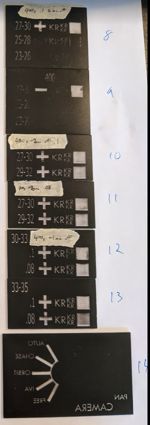
    I stuck with 400 speed throughout these tests. My first plan was to engrave once in focus, and then polish (because my out of focus tests on day 1 resulted in blurry text). So first I had to identify a power setting that was just enough. In swatch 8, I did that: we want 400 speed, .1 interval, at 27-30 power. This was about 2mm out of focus already, which I actually didn't realize. In swatch 9, I did the same thing, but then polished at 10% power in a second pass way out of focus (like 4mm). This looked worse: I think perhaps what's happening is that black acrylic is melting in to the engraved areas, but I may be missing something. 

    Swatch 10-11 I'm refining my power settings. 12 I try a smaller interval (it didn't help). 13 I try a little more power, and finally get a pretty good result. in swatch 13 (line 1), the text is crisp and there is minimal noise in the engraved areas. Then I tested one more time in a part of my final design in 14 (I missed some defects, eg....

    Read more »

  • The messy middle: PCB and Backlight Troubleshooting.

    Matthew Peverill06/08/2020 at 22:02 0 comments

    So my makerspace is open again! Yay! That means I can get back to work. Unfortunately, lots of mis-steps. One problem is my PCB, which continues to be shorted out. I have fixed a lot of problems with it but at this point there are no visible manufacturing issues which makes me think there is something wrong with the design: not sure how to fix that. Maybe I will make a Kicad forum post later. In the mean time, let me talk a little bit about something I do know something about, which is how to make a back-lit panel (what I know about it is that it is a PITA). I've tried two approaches, with comparable results. The big lesson is: you need to test new materials with every size of engraving you're doing. Just because a setting works on your smallest text doesn't mean it will work on your larger engraved areas.

    Attempt #1: Painting

    Ok so for this approach, I took a sheet of 1/8" thick 40% transmissible acrylic sheeting, roughed it up with sandpaper, primed it, and then painted it with several layers of matte black spray-paint. Then I put it in the laser cutter and carefully tuned the settings to take off just the paint (see last post). The result is just ok:

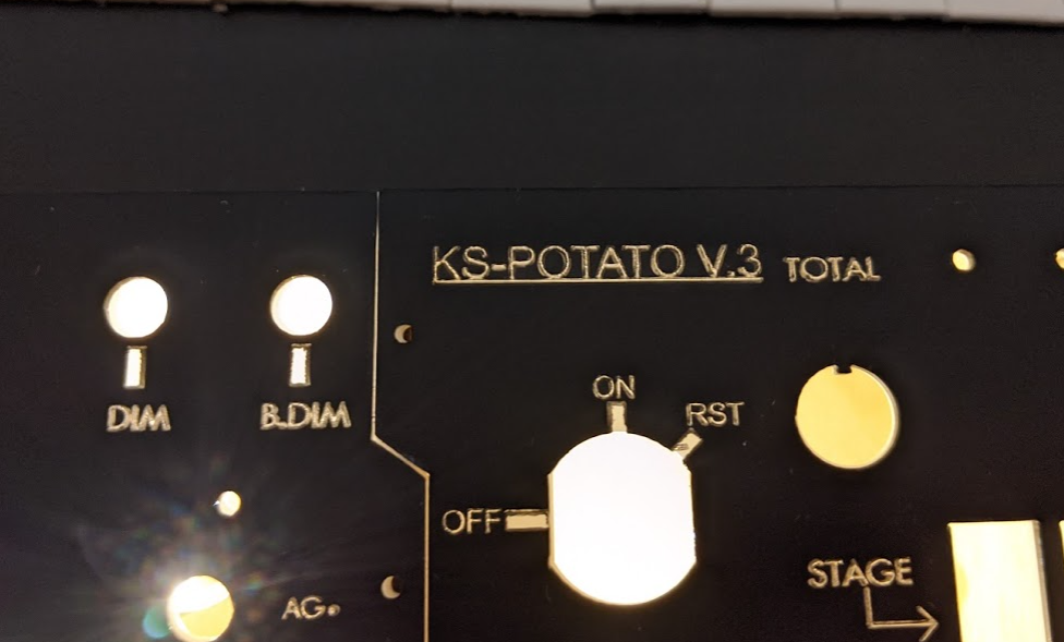
    Without backlighting, the text is hard to read because the contrast between the acrylic and the paint is not that high. Partly it's because the acrylic is gray-er than I thought, and partly it's because particles of paint become embedded in the rough surface where the laser engraves. You can see at the bottom where I tried to clean this out with alcohol: this dissolves the paint and makes it look worse. Also I'm not good at painting, so the surface is marred to begin with. With backlighting it looks better, but there is still some visible mess in the engraved areas, which is too bad (and also I'd like it to look good to the eye):

    If I had used an adhesive to protect the surface, it may have helped. I also think I might have seen less powdery paint nonsense if I used a non-matte paint, but I have no evidence for this.

    Attempt #2

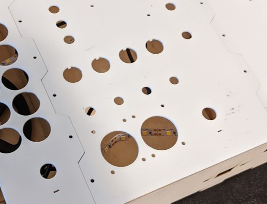
    Attempt #2 was a combo. First I used a 1/16" thick layer of 30% transmissable acrylic without engraving to serve as a diffuser (incidentally, doing this also means we can cut things like the anti-rotation for the rotary switches in to just this layer, which makes the whole thing neater):

    Then a layer on top is reverse-engravable black and clear acrylic:

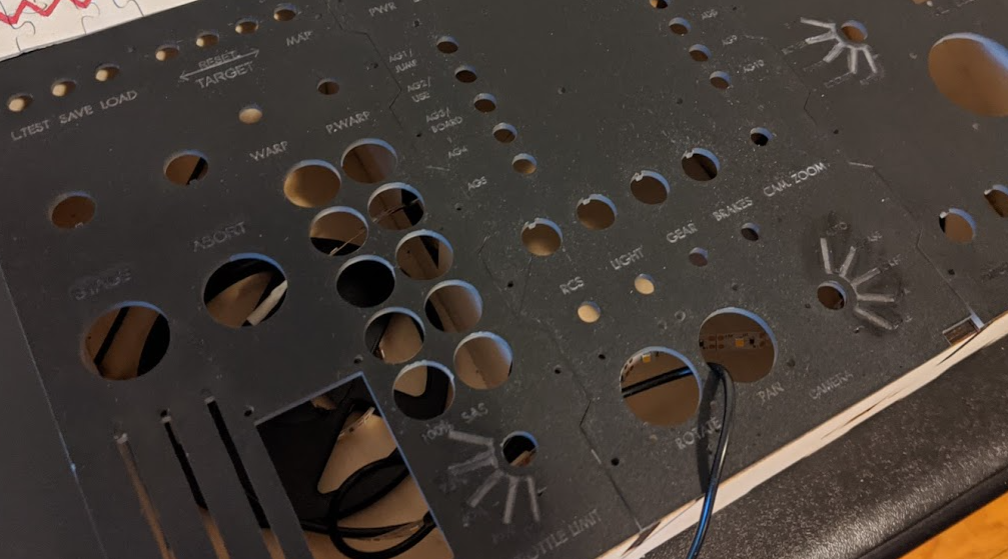
    This stuff is really cool. You engrave on the back side, and then the top remains totally smooth because the engraving is on the bottom and seen through the clear layer. My tests looked amazing and I was really excited about it. Unfortunately, you can see that the settings didn't quite work. The small text is still hard to read (maybe a bit better than the last), despite extensive tuning. The larger engraved areas are actually totally burned away. I probably needed a bolded and/or larger font size and a lower power setting. Also, you can see some surface marring (I believe because the tape I used to protect the surface during cutting had air bubbles and may have caught on fire a bit). 

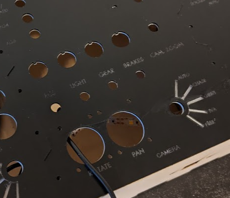
    The backlighting does look a bit better, but still not quite spick and span:

    Were I doing this again, I'd probably use the materials from attempt 2, make the text bigger, and reduce engraving power. I'm not sure I'm willing to shell out another $35 to do it though: we'll 

  • Backlighting Prep

    Matthew Peverill03/19/2020 at 01:01 0 comments

    Finally got to test engraving on my painted acrylic today and it worked pretty well! Here are my test patches (engraved on a cutout from the test panel):

    Most recommendations for engraving on acrylic will take off far more material than we want to. On our laser 150watt laser cutter, best results are from a speed of 500 and a power setting of 30-40. (this is the center square in the column of three and the text). The bottom square was a little under-burned, and everything else took off too much material. 

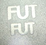
    The text looks a little fuzzy relative to what it looked like on the SVG file, although not so bad we couldn't deal by spacing out characters. If you look closely, you can see that this is because the edges don't line up between right and left passes (here it is under a microscope):

    RDworks has a setting for 'overstrike' which might be able to resolve this, but I can't find any clear documentation about it. This instructable has guidelines on how to fix just this issue by adjusting the reverse interval setting, so that's what I'll try next. 

    That said I'm super happy with this result! The text looks nice and white under top-light, and is semi-transparent to backlighting. Possibly I would have done 30% transmissable (instead of 40%) given another chance to make it whiter. 

  • Panel Preparation

    Matthew Peverill03/10/2020 at 20:28 1 comment

    So my final plan for printing the panel is as follows:

    1. Paint the semi-transmissible acrylic sheet with black paint
    2. Laser cut the panel, using the engrave setting to burn through the paint.
    3. Laser cut a mask for the engraved areas on paper.
    4. Do any additional drilling necessary.
    5. Spray paint over the mask in order to paint the cut edges.

    This will work, I think, but I want to say that painting acrylic is way more of a PITA than expected. Don't expect to just grab a can of spraypaint and give it a once over: you need to sand it, prime it, sand it again, then let it dry for 24 hours, then spraypaint it. If I were doing this again, I'd think about whether I could make this work using the engraveable two-tone acrylic sheets that inventables carries (maybe with another sheet of something as a diffuser?)

  • Intermission: New PCB and Lessons Learned

    Matthew Peverill03/10/2020 at 20:25 0 comments

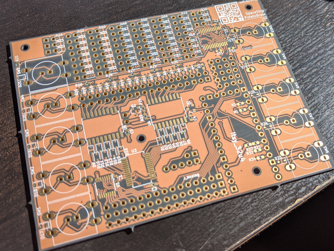
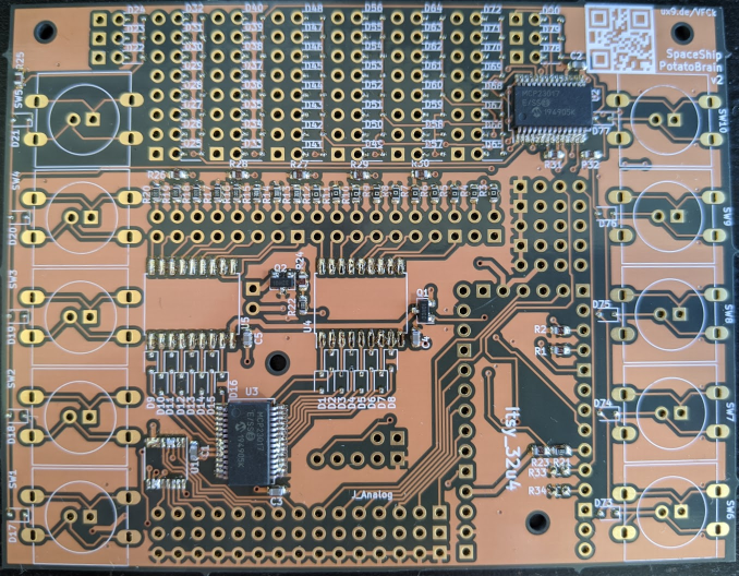
    New boards are in and I've had my first experiences with surface mount soldering! Here's the board (I used OSHpark this time - the dark as night clear soldermask is pretty sweet:

    Huge thanks to the helpful folks at the Bodgery in Madison, WI for helping me figure out how to use a reflow oven and the manual pick and place. As usual, here is a list of my 'lessons learned' e.g. stuff I did wrong:

    1. For heaven's sake, make sure you have all the components before you start stenciling (I forgot diodes! The part I have the most of!).
    2. Use plenty of solder paste - if you don't have enough you have to make multiple passes, making solder bridges more likely for fine pitched parts.
    3. In KiCad, there are a number of potential sizes for SSOP chips - make sure you have the right one. I had an overly tiny footprint for my 74HC4051 chip. I couldn't find a part in that exact form factor, but it looks like I can use a TSOP package instead.
    4. Actually, 1 and 3 can be resolved the same way: print out your PCB on paper and place your components on before you start soldering. Stencils and solder are expensive.
    5. Again, make sure you understand how all your components work. Turns out the shielded, led lit toggle switches I use have sort of a funny circuit: they combine a pull down resistor and led and use a 3 pin toggle. That is to say: You can't measure the toggle with a pull up and use the LED independently, so I now need to repurpose my quick save quick load pins for them (which is why those resistors are not bridged in the finished board.

    All that said, my outcome was not bad, I just need to replace 3 of my chips and the diodes, then put it on a hot plate. I'll also need to clean up some solder bridges on the placed ICs using a wick.

    Finally, just a note to people who are doing their own controllers: building your own PCB is pretty fun. It makes me feel smart, gives me a lot of control over panel mounting options, and gives that impossible to beat feeling of making something. That said, please don't think it's necessary for a controller. The Adafruit Grand Central has all the features my board has, minus a few digital inputs (which could be easily added using an add-on board) and the switches (again, could be added using an add-on board). Even if you need to buy a few add-on boards, I guarantee you will save money using pre-packaged products rather than buying all the tooling (and extra parts) needed to roll your own. Even if you do need to make some of your own stuff, it's cheaper to print a few small boards than one big one (less so with JLCPCB, admittedly).

View all 31 project logs

Enjoy this project?

Share

Discussions

George Gardner wrote 02/14/2020 at 02:21 point

This is fantastic!

  Are you sure? yes | no

Similar Projects

Does this project spark your interest?

Become a member to follow this project and never miss any updates