Matthew Peverill
-
Future Proofing for 2.0
08/22/2019 at 19:33 • 0 commentsSo Kerbal reddit is aflame with news of Kerbal Space Program 2.0! Time will tell how the new team does with it, but what we've seen so far is pretty cool. I'm not hugely in to the far future stuff, but it looks to be a bigger game in general, which is awesome.
But more relevantly: it would be a shame if we had to rebuild this thing entirely for a new system! How can we guard against that? My feeling is that there will be some analog of kRPC or equivalent that I can talk to, but it may take some time to be feature complete. In the meantime, it would be nice if we could do this without complicated software. How can we do that? By emulating a joystick!
The ATMEGA328P, which is the chip that powers most arduino based controllers (and both of the ones I've used with this project so far) is too slow to emulate a USB device. But the ATmega32u4, which is in the Teensy 8 bit microcontrollers as well as some of arduino and adafruit's lineup, can. So can the 32 bit chips in Adafruit's M0 line. Possibly I should just go for that, but 8 bit just feels so nostalgic (plus I don't need to do a pass over all my designs to convert them to 3V logic).
1. The USB plug: classic arduino uses a USB-B cable. I've been a bit stubborn about this one, because I feel like the micro cables might be less resilient, but at this point everyone has a million of them lying around, so I can probably let it go.
2. Power: The Arduino has the option for an external power source, bumping up the available power from 400mA or so to about 900mA. One thing we'll need to do during testing is calculate how much power everything takes in operation (we can always install our own power jack separate from the microcontroller's supply).
3. How big a joystick can we make? We have 11 analog controls and up to 64 digital on this sucker, and even the mightiest HID device can't support that many. BUT we can do a workaround: one board can emulate multiple HID devices, so we can present as more than one joystick. Problem solved.
This should be a good option to make the board more flexible for either KSP version.
-
Further testing, the urge to start over, and rotary encoders.
08/20/2019 at 15:49 • 4 commentsOK - I tested input on my throttle panel! Apart from the afore-mentioned issue with the pull up resistors, it works fine. There are a few (like, 2) that I didn't wire with resistors, I think because I originally planned to build them in to the rotary switches, but no biggie.
None of these issues is insurmountable (I can just use a breakout to provide 5V to my switches). However, it's really tempting to start over rather than spend time hacking around them when I could just start over. I'm already excited to:
- Put everything on one board with surface mount connections.
- Use a button matrix with one I/O expander instead of 4 I/O expanders.
- Use rotary encoders!
It's a mistake to actually rebuild before I've tested everything, but there's no harm in thinking about it and planning.
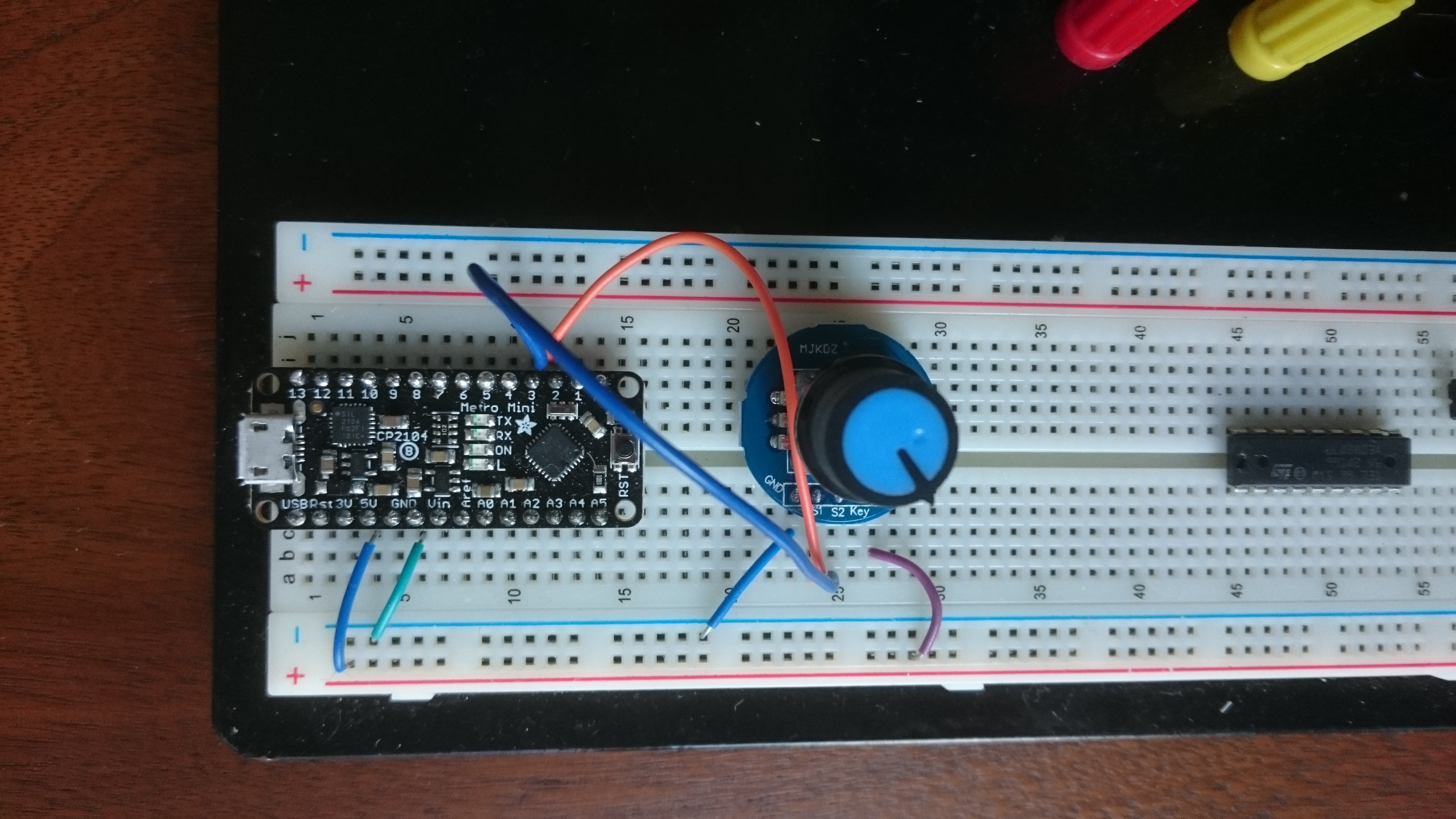
Planning for Encoders
![]()
Today I'm thinking about rotary encoders. These are rotary switches that can be rotated indefinitely. They output to two pins that turn off and on in a stepped pattern such that, if you read constantly, you can tell which way they are being rotated (other people have written about this better than I). They would be so much nicer for the time warp switches and the camera zoom. But there is little consensus about how to configure multiple encoders. I'd need three, so the gold standard method of using interrupts is out. Some sources suggest that, if they are hand operated and don't go too fast, it will be fine to wire the outputs to a button matrix. A more foolproof (but more expensive) way is to purchase a couple of i2c encoder daughter boards for about $20.
How can we tell if we'd be ok polling? First, we need to know how often we need to poll to reliably capture hand rotated encoder signals. There's a lot of "it worked for me" and "I would never try that", but little data, so let's do some testing.
I'm using PaulStroffregen's Encoder library. The github page includes some example sketches that are perfect for what I'm trying to do. First, I loaded up the 'Basic.pde' sketch just to see what things worked like with interrupts (the 'right' way). Then I loaded up 'NoInterrupts'. These two work pretty much the same if there is nothing going on. Output should look like this:
Basic NoInterrupts Test:
0
1
2
3
4
5
6
7
8
As you turn the encoder, each detent corresponds to an increase (or decrease) of four. Sometimes you the detent won't quite 'land' and you get stuck in between, but it will settle to a multiple of four with a little movement (note to self: going to have to deal with this when we get to actual controls).
Next I uncommented the delay line in the NoInterrupts sketch and set it to 20ms, which is a pretty reasonable loop interval for the whole device. No dice at all - first off, even on small turns (one or two detents, a step can be missed (which would screw up some coding schemes). Large turns are completely lost - I can turn 10 detents and the counter only goes up by 9 or so (it should go up 40). So if you were using an encoder for something rather imprecise, that might be fine, but might end up crashing us in to the sun. So i2c controllers it is!
-
Update: digital input testing.
08/17/2019 at 22:50 • 1 commentOk move is complete, in a new space, time to get hacking!
New Issues
Still troubleshooting the prototype box. I've found a few new issues to put on the to-do list for the next iteration:
- The RCS control is too long, it sticks out of the box in a way that is sort of unpleasant and, more importantly, the interior division that I've used to support it doesn't leave enough room for the cables coming off the arduino, which need a good 2-3 centimeters of headroom. This is workable in the prototype, but it means the box doesn't quite close right.
Progress
I identified some cable pairs that aren't broken in my long cables! I was able to verify this by loading up Adafruit's led bargraph test - it works fine. This means I can troubleshoot my daughter boards for real now. PCBs and boxes are expensive so I want to find all the problems I can before I redesign.
Notes for Today:
First, Troubleshooting the action button PCB. Once I got my wiring sorted out, I ran my I2C multiplexer test that I've already gotten to work on a breadboard:
#include <Wire.h>

void mux_Tx(int adr, int reg, byte data) {
  /* This function will send data to a MCP23017 chip */
  Wire.beginTransmission(adr);     /* address the chip */
  Wire.write(reg);                 /* point to the register of choice */
  Wire.write(data);                /* send the data */
  Wire.endTransmission();          /* end the transmission */
}

void mux_Rx(int adr, int reg, int numbytes, byte *data) {
  /* This function will request n bytes of data from a MCP23017 chip */
  Wire.beginTransmission(adr);     /* address the chip */
  Wire.write(reg);                 /* point to the register of choice */
  Wire.endTransmission();          /* end the transmission */
  Wire.requestFrom(adr, numbytes); /* request the data */
  *data = Wire.read();
}

void printBin(int var) {
  for (unsigned int test = 0x80; test; test >>= 1) {
    Serial.print(var  & test ? '1' : '0');
  }
}


void setup() {
  Serial.begin(9600); // Initialize the serial port
  Serial.print("I'm awake!\n");
  /* wake up the I2C_bus */
  int n_mux_chips_detected = 0;           /* number of MUX chips detected in the IBIT */
  const int c_num_mux_chips = 2;
  const int c_first_mux_address = 0x20;     /* the first I2C address in the MUX range [-]*/
  const int c_last_mux_address = 0x21;      /* the last I2C address in the MUX range [-]*/

  Wire.begin();
  Serial.print("Started Wire\n");
  /* check we have all the MCP23017 chips */
  for (byte a = c_first_mux_address; a <= c_last_mux_address; a++)   /* chip addresses start at 0x20, max of 8 chips */
  {
    Serial.print("Testing ");
    Serial.print(a);
    Wire.beginTransmission (a);
    int testval = Wire.endTransmission ();
    Serial.print(" returned ");
    Serial.print(testval);
    Serial.print("\n");
    if (testval == 0) {
      n_mux_chips_detected++;
    }
  }

  Serial.print("Done testing, detected: ");
  Serial.print(n_mux_chips_detected);
  Serial.print("\n");
  if (n_mux_chips_detected != c_num_mux_chips) {
    Serial.print("mux miss");
  }

}

void loop() {
  byte buffb=0;
  mux_Rx(0x20, // i2c 0
         0x13, // GPIOB
         1, // Start at register 1
         &buffb); //write to buff
  byte buffa=0;
  mux_Rx(0x20, // i2c 0
         0x12, // GPIOA
         1, // Start at register 1
         &buffa); //write to buff
  byte buffd=0;
  mux_Rx(0x21, // i2c 0
         0x13, // GPIOB
         1, // Start at register 1
         &buffd); //write to buff
  byte buffc=0;
  mux_Rx(0x21, // i2c 0
         0x12, // GPIOB
         1, // Start at register 1
         &buffc); //write to buff
  Serial.print("0x20A: ");
  printBin(buffa);
  Serial.print(" 0x20B: ");
  printBin(buffb);
  Serial.print(" 0x21A: ");
  printBin(buffc);
  Serial.print(" 0x21B: ");
  printBin(buffd);
  Serial.print("\n");
//  Serial.println(buffb,BIN);
  delay(100);

}
When I run this with my action panel wired, serial monitor cheerfully reports:
I'm awake!
Started Wire
Testing 32
Without going in to too many details, this indicates that Wire.beginTransmission or Wire.endTransmission hung without exiting cleanly. This usually means the i2c device isn't responding, which probably means a hardware issue (at least, if your board was hacked to gether by an amateur that is likely.
Ok so, basic continuity testing worked fine in as far as my harborfreight multimeter could detect. I next used a voltage meter to measure between the i2c pins meant to be at 5V and ground and found that they are only getting about .5V when they should be getting 5V. Voltage between ground and power pin was fine. What could be going on? Turns out something very embarassing:
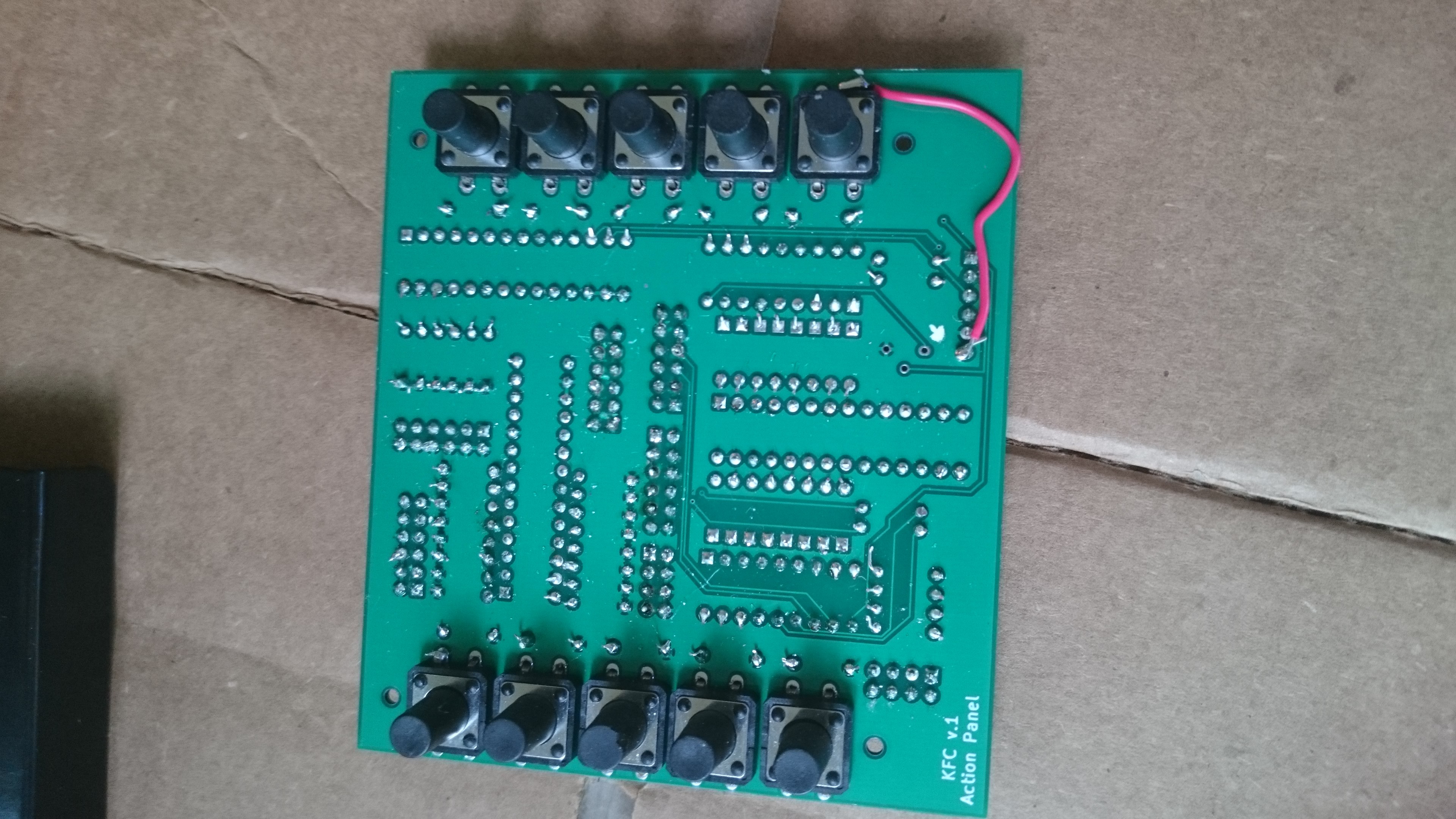
My power pin isn't connected to the power plane! I have some unconnected pins because they were going to be connected by my switches, but I must have missed this one. Too bad. Crude problems sometimes merit crude solutions:
![]()
Ok now when I plug it in I get:
I'm awake!
Started Wire
Testing 32 returned 0
Testing 33 returned 0
Done testing, detected: 2
0x20A: 00000000 0x20B: 00000000 0x21A: 00000000 0x21B: 00000000
0x20A: 00000000 0x20B: 00000000 0x21A: 00000000 0x21B: 00000000
...
0x20A: 00000000 0x20B: 00000000 0x21A: 00000000 0x21B: 00000000
0x20A: 00000000 0x20B: 00000000 0x21A: 00000000 0x21B: 00000000
0x20A: 00000000 0x20B: 00000100 0x21A: 00000000 0x21B: 00000000
0x20A: 00000000 0x20B: 00000100 0x21A: 00000000 0x21B: 00000000
0x20A: 00000000 0x20B: 00000100 0x21A: 00000000 0x21B: 00000000
0x20A: 00000000 0x20B: 00000100 0x21A: 00000000 0x21B: 00000000
0x20A: 00000000 0x20B: 00000000 0x21A: 00000000 0x21B: 00000000
0x20A: 00000000 0x20B: 00000000 0x21A: 00000000 0x21B: 00000000
0x20A: 00000000 0x20B: 00000000 0x21A: 00000000 0x21B: 00000000
0x20A: 00000000 0x20B: 00000000 0x21A: 00000000 0x21B: 00000000
0x20A: 00000000 0x20B: 00000000 0x21A: 00000000 0x21B: 00000000
0x20A: 00000000 0x20B: 00000000 0x21A: 00000000 0x21B: 00000000
0x20A: 00000000 0x20B: 00000000 0x21A: 00000000 0x21B: 00000000
0x20A: 00000000 0x20B: 00001000 0x21A: 00000000 0x21B: 00000000
Progress! We hit both chips. As we press the buttons, the corresponding registers switch to 1s. Then we just need to test each action button and all the other inputs via a jumper.
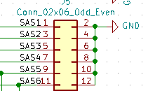
Action button 6 was not working because of a bad solder join. Testing also showed that not one of the jumpered switches was working. This is due to another embarassing error, unfortunately not one I can fix here:
The switch jumpers are hooked in to the ground plane instead of the 5v. So jumpering them doesn't change the state of the MCP pin at all. No wonder they don't work. This will also affect the throttle panel :( . So it's back to the drawing board with those!
-
The Shield PCB (and a solved mystery)
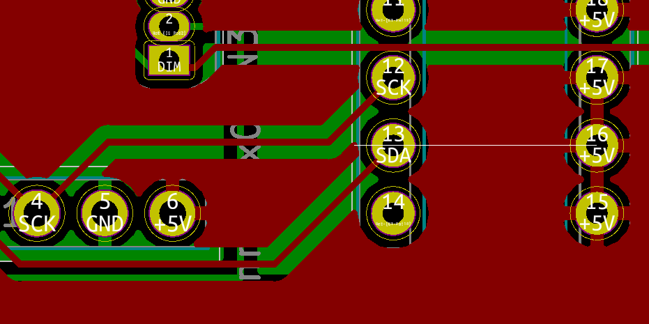
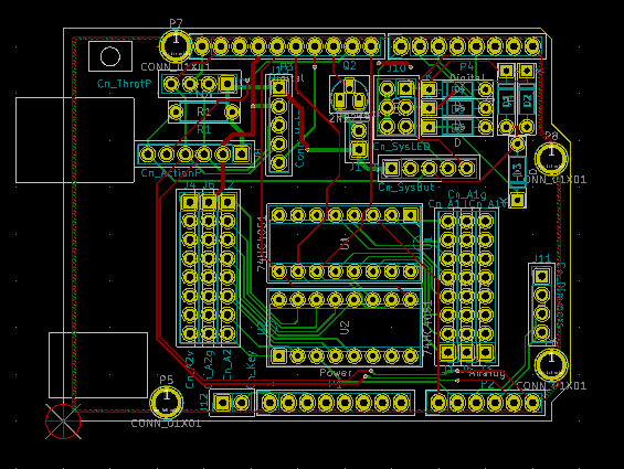
06/07/2019 at 05:05 • 3 commentsThe idea with the shield was to host the analog multiplexers and some of the lamp test electronics, as well as to break down the pin connections in to logically sensible headers. The schematic is on github. Here's the board:
The connector in the top left is the one I'm trying to test. In order from right to left the pins are: Vcc, Gnd, A5 (SCL), A4 (SDA).
Continuity tests on the board show those pins connecting to the relevant headers, and not to each other. My i2c device works fine if I plug it directly in to my arduino, but it fails if I plug it in to the ports in my shield. So what could else could be going wrong? It's the cables - the extra long female to female jcp cables I ordered from aliexpress are nearly all completely useless. When I hooked it up with a 6" cable it works fine. Lesson learned - now I just need a different source for 20" female to female ribbon cables :(
-
Time Warp
06/06/2019 at 06:53 • 0 commentsOk so I had LOTS of problems solved up to the present moment. Need to get a little less perfectionist about posting. In brief:
- If you make your own PCBs, don't just trust the footprints for your components will work (both my rotary switches and my microswitches didn't have big enough drill holes: they had to be widened).
- Don't buy parts that don't come with a footprint diagram.
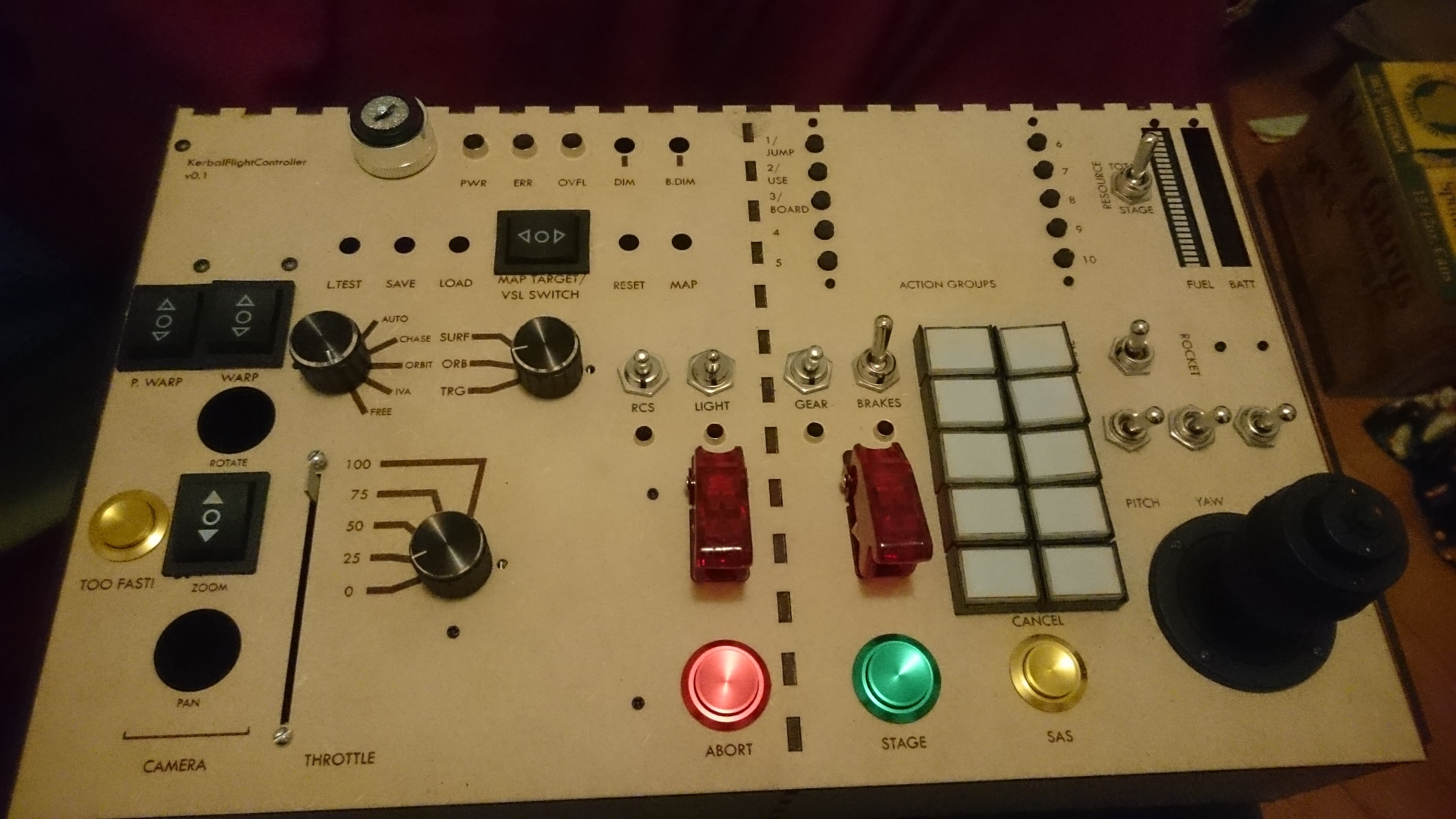
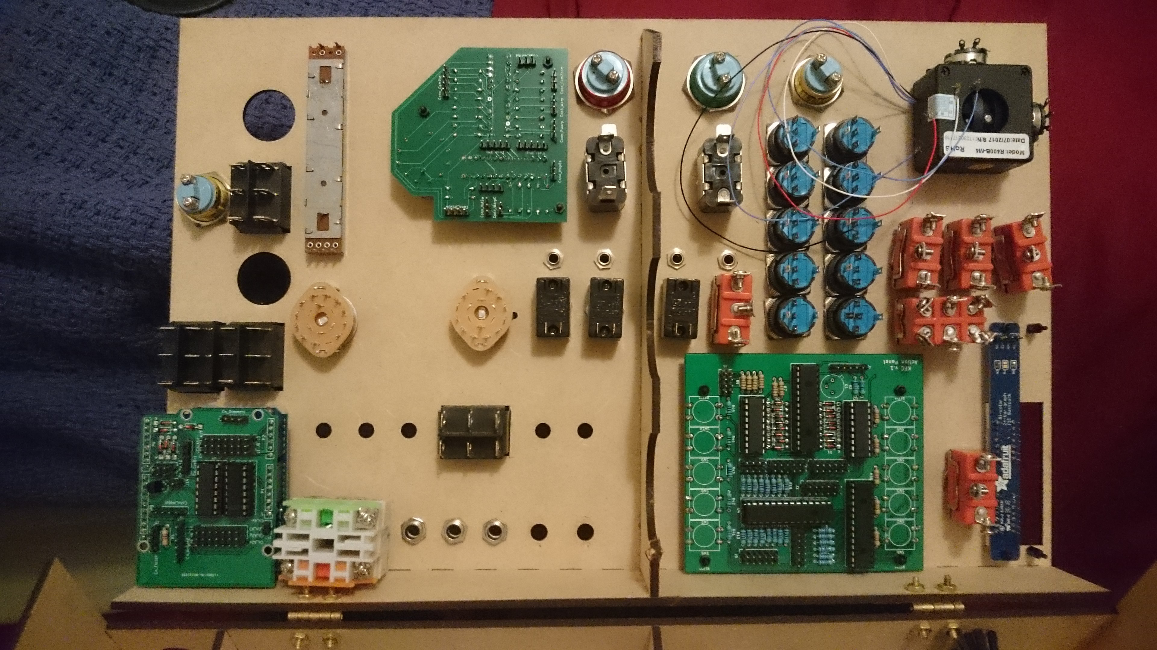
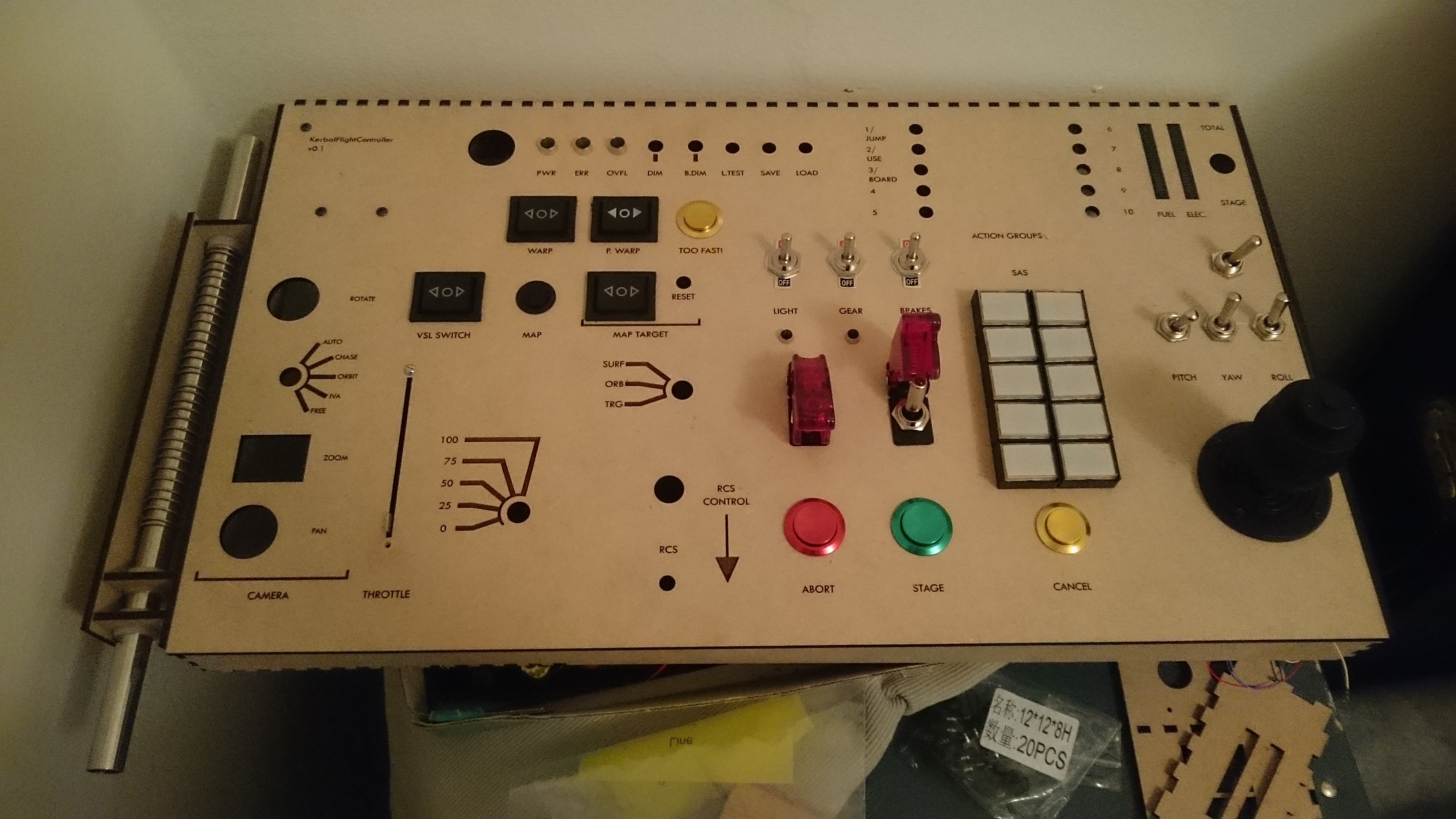
I have a new prototype which looks great:
![]()
It's also mostly intact on the back, including my shiny new PCBs! I have:
![]()
The shield (the thing that snaps on to the back of the arduino to provide connections to the other boards and analog devices)
The action panel (the thing that provides most of the digital i/o and which has the action buttons on it.
The throttle panel (which has the rotary switch inputs and some other i/o on it.
If I had known how PCB pricing works when I started, I would have tried to make one shield panel to go under the action panel and used surface mount parts. Maybe next time.
It is not, of course, working yet. At the moment I have a problem where, if I hook up a purchased i2c device (like the adafruit bar graphs) to my arduino with a breadboard, it works fine, but if I try to hook it up through my shield board, it doesn't work. So probably there is a flaw in the shield board (bummer). I don't really know how to figure out what it is though - guess I'll have to do some research :)
-
Haptic Motors
02/11/2019 at 06:34 • 0 commentsSo the second circuit I tried to lay out was the vibration motor circuit. I used one that is fairly typically seen online with a diode and a small capacitor in parallel with the motor. My motor turned on, but I realized pretty quickly that it was going to be difficult to make the sort of effects I want.
Instead, I will probably use a haptic motor driver, which seems to be the usual response. Otherwise, I think I'd end up running in to weird timing issues, and I want to save processor speed for serial response as much as possible.
-
Circuit Development Part 1 - Light Control
02/05/2019 at 08:40 • 0 commentsPCB development is ongoing! After talking to the amazing Kicad forum people about how to design an amateur-friendly PCB without soldermask, I was convinced that I should just send a design to a board house. This means I want to be extra sure my circuits work, which means prototyping things on breadboard.
Parts of the circuit I'm quite comfortable with (I2C I/O expanders, switches with pull-up/pull-down resistors). BUT there are two parts that are a little less comfortable. One is the vibration motor, which I'll address next time. The other is LED control.
My design calls for some LEDs to be driven off the arduino directly for maximum fail-safe capability in the event of a hardware problem (power, error, overflow). Other LEDs are to be driven by ULN2803A darlington pair arrays. The basic premise of these latter is to allow the microcontroller to control logic while providing steady current (and avoid drawing too much current through the controller chips and burning them out.
Now, the complications are that we also want:
- A PWM dimmer control wire that is common to all LEDs on the board.
- A 'lamp test' circuit that turns on all LEDs through a hardware switch when pressed.
The latter is easier. We just use diodes to provide alternate current to the anode when a button is pressed, which effectively over-rides the arduino pin. You need another set of diodes connecting the arduino to the anodes, so that you don't short out the arduino pins (fun fact - my arduino didn't burn out when I did this the first time, but it did cause flickering when the lamp test was on). In the case of the ULN, you can hook up the common emitter pin to ground the switch. When the switch hooks to ground, the common emitter is grounded and all the LEDs light.
The PWM is more tricky. For the board controlled lights, you can just map an analog in to the PWM pins and, presto, you're good to go. BUT I don't have enough PWM pins to drive every LED. Instead we use some transistor trickery to turn off the ground pin on the ULN using a common PWM pin. Full disclosure: I don't fully understand how this works and, like a lot of my project, it's cribbed from Petewasere's github page.
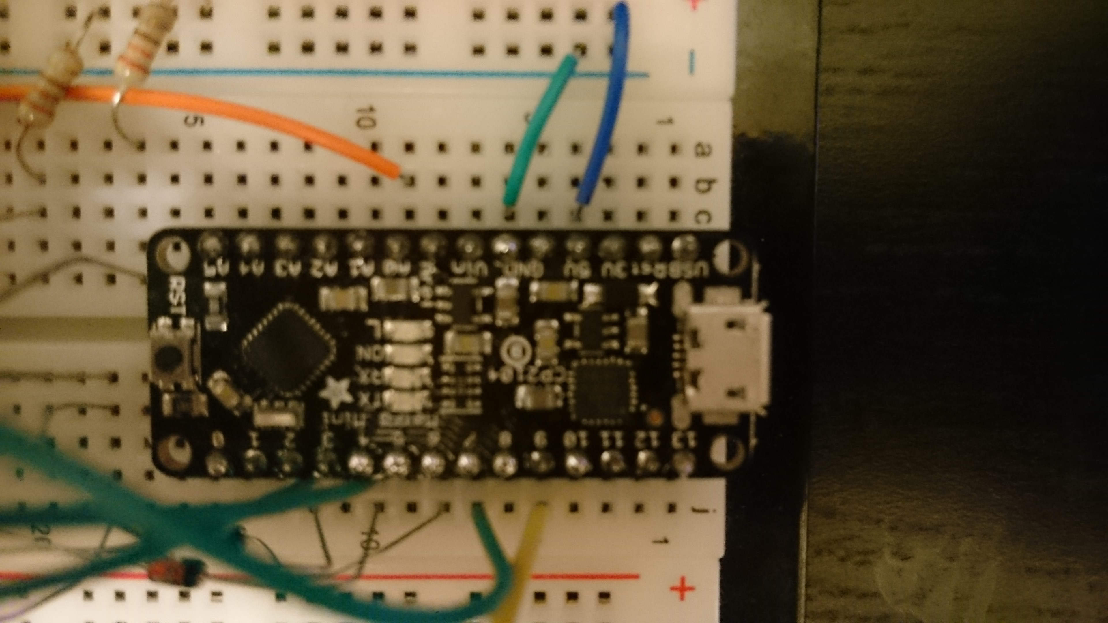
OK so I bought an adafruit metro mini so I don't have to unplug my arduino from the panel (almost got the M4 version, but I wanted an equivalent). I soldered on the pins and plugged it in my breadboard. My soldering is decidedly just ok:
![]()
Look at those blobs! Seriously those this thing is great for breadboarding.
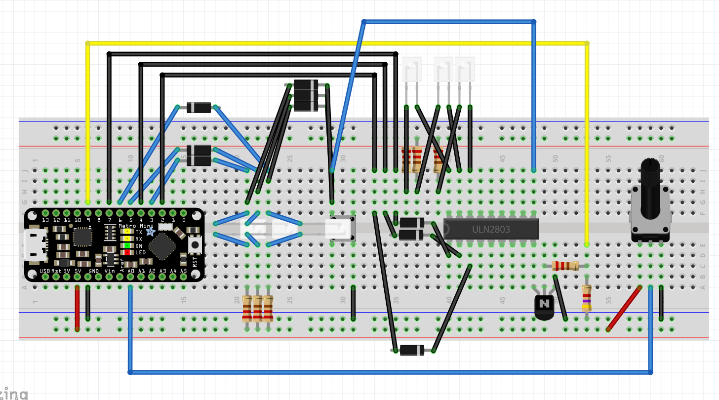
I'm going to spare you a lot of the troubleshooting. Here's the final circuit in fritzing (which I'm not using for PCB design, but is (somewhat) helpful for breadboard illustrations:
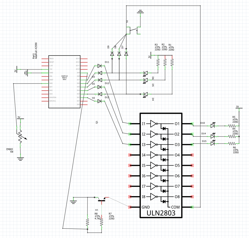
Here's a terrible schematic:
Code can be found here:
https://gist.github.com/mrpeverill/9cb6b14f50befc2daf1d557ecb9a955d
Code is pretty simple. The only complication is that you have to sign flip the PWM signal for one set of LEDs for another. I'm pretty sure I could get around that with a PNP transistor, but I don't have any (edit: yes this totally works!).
Here's a video:
-
Thoughts about circuits
12/11/2018 at 04:55 • 0 commentsGood news, no major problems with the panel. It now looks like this:
![]()
This led me to start thinking in more detail about how to actually connect everything. My original plan (at least for the prototype) was to use stripboard, and I spent a lot of time today looking in to stripboard prototyping. Unfortunately, when I got home to start doing that I realized that several of my components simply won't work with veroboard because of pitch problems (in particular, the game controller joysticks used for camera controls, and the resource lights. It's possible that, If I'm going to have to use PCBs, I should just use them for everything. I have an old kicad file describing some of the circuits, and I can fab things at a makerspace nearby.
More fruitfully, I spent some time thinking about wiring. I was going to just solder wires to headers, but the article above said I shouldn't do that. A little googling and I realized I can get JST connectors to use with ribbon cable, which will be much neater.
-
Laser Cutting Prototypes
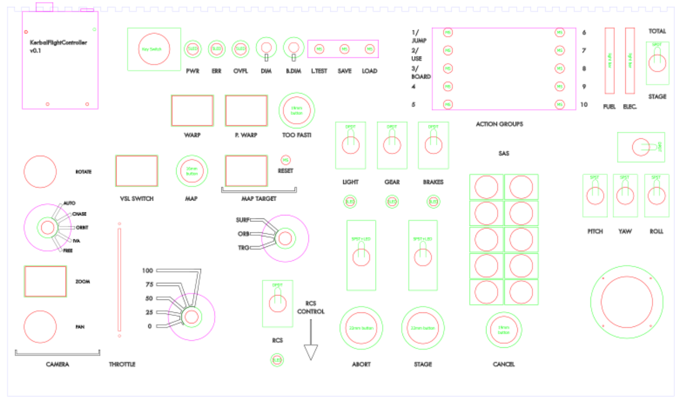
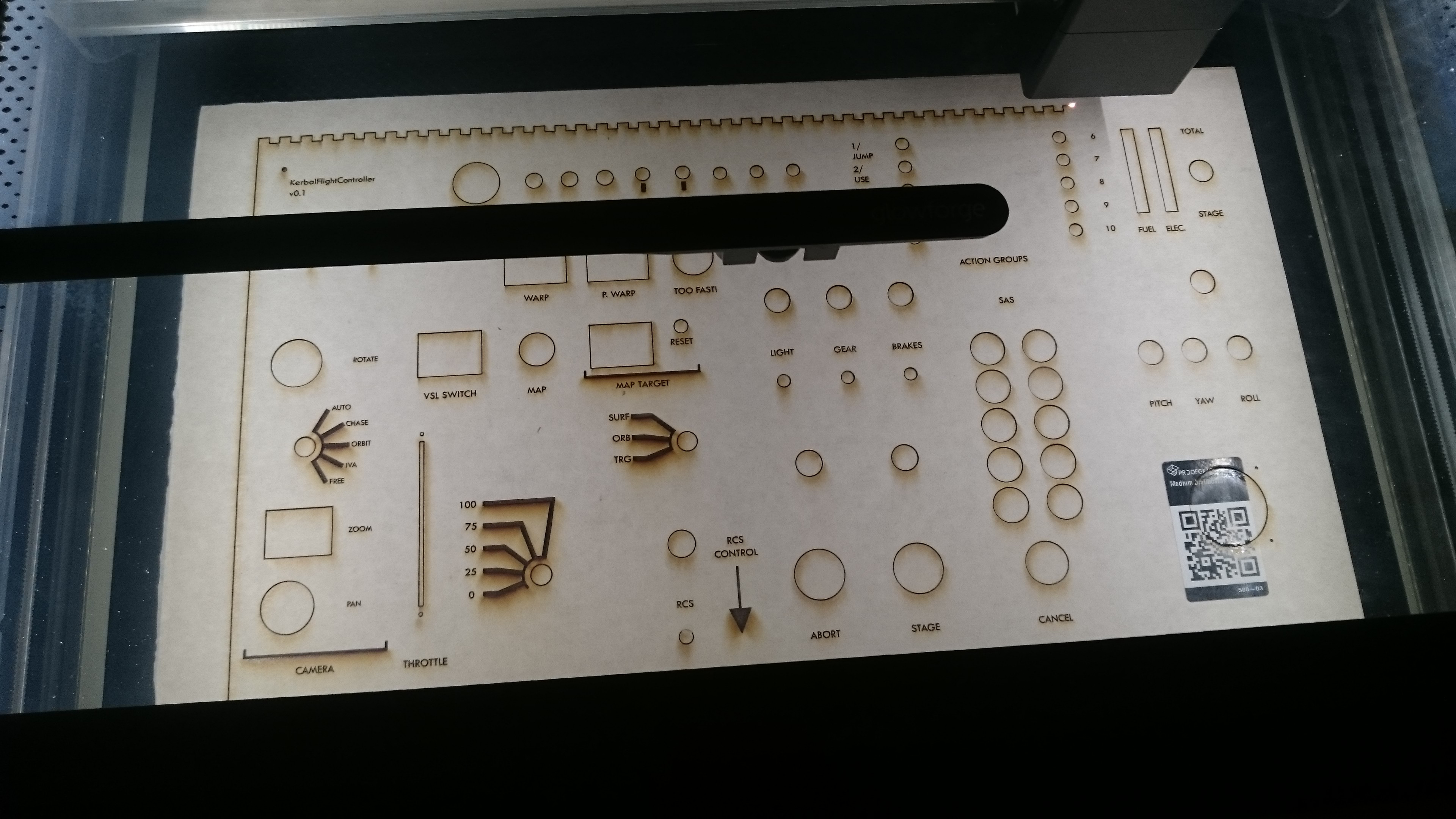
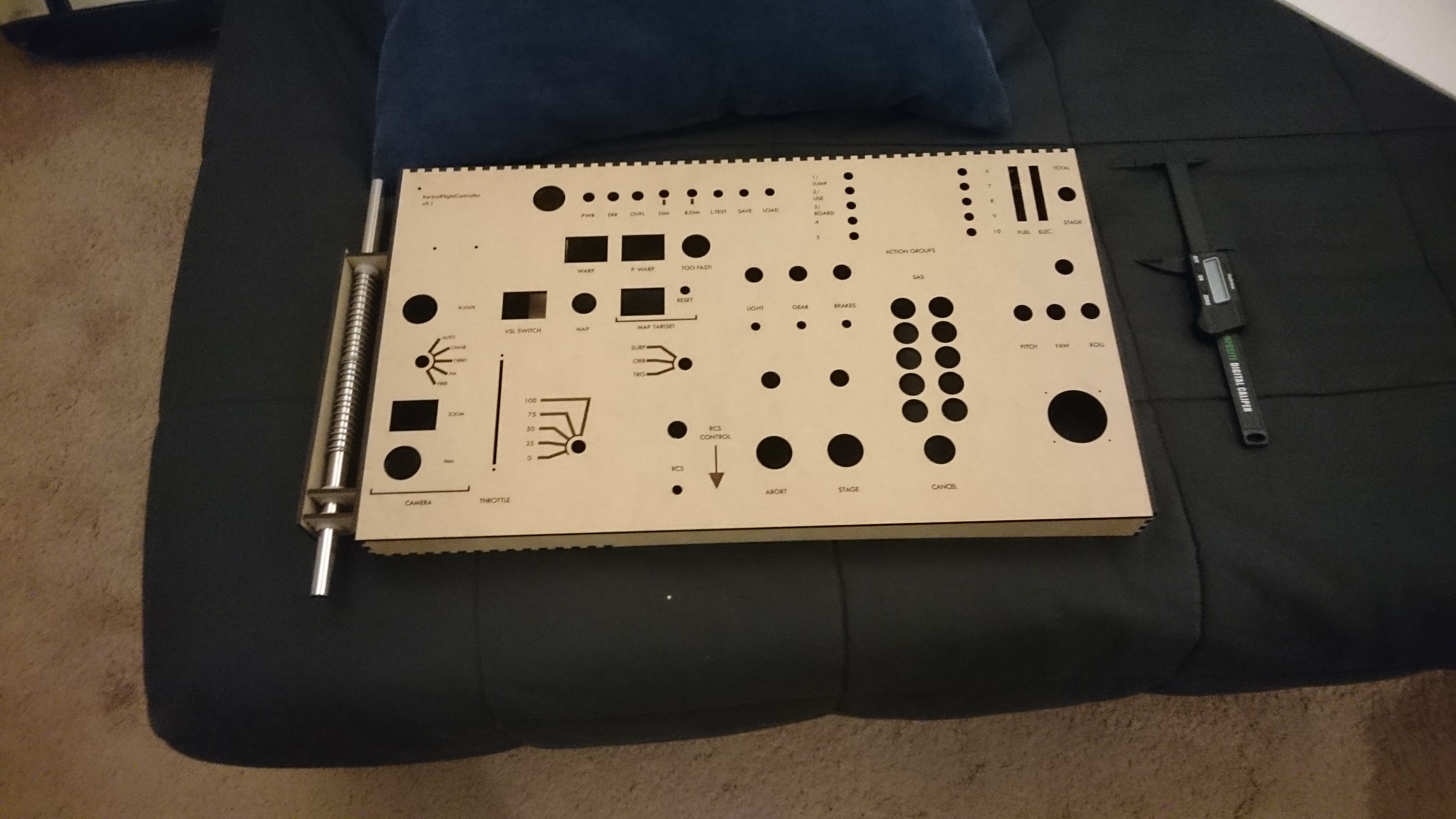
12/02/2018 at 07:22 • 0 commentsJust finished lasercutting my first solid prototype on my friend's glowforge! For those not familiar: you start out making a vector drawing in inkscape, then upload it to a web app. Specify which colors are engrave and which cut, and press the button. I used the excellent Tabbed Box Maker to build an enclosure. I tried to cut it so that the top (with the switches) could hinge out from the rest. Here are some pictures:
![]()
![]()
![]()
![]()
There are a few issues, justifying the prototype status:
- The final product ended up a bit bigger than I was visualizing it. I may be able to shrink it during development, but the extra space will likely be helpful for now.
- The space/rocket switch isn't labelled.
- The screw holes for the arduino aren't quite big enough.
- I didn't cut holes for the tabs in the rotary switches. These are designed to keep the base rotationally fixed, and are required for them to sit flush with the panel.
- The rocker switches I use aren't reacting well to being squeezed in the long direction - they are a bit stiff.
- The box is a bit flimsy - it would have helped to make it deeper, and/or to build in some crossbars. This will also help with the feel of the buttons (since the panel flexes a bit atm when you press).
- Still - it's looking pretty good! The action group buttons fit perfectly.
Over the next few days I'll go through the different parts in more detail as I put it together, and I'll finally talk about how I picked parts.
-
Early Steps
12/02/2018 at 07:13 • 0 commentsI'm going to skip over some things, since I've already done this.
- First, I forked PeteWasEre's github repo for the kerbal controller. I took out all the autopilot code (not using it), and changing the formatting in the gui to confirm to my bizarre aesthetics (mm ambervision monospaced fonts).
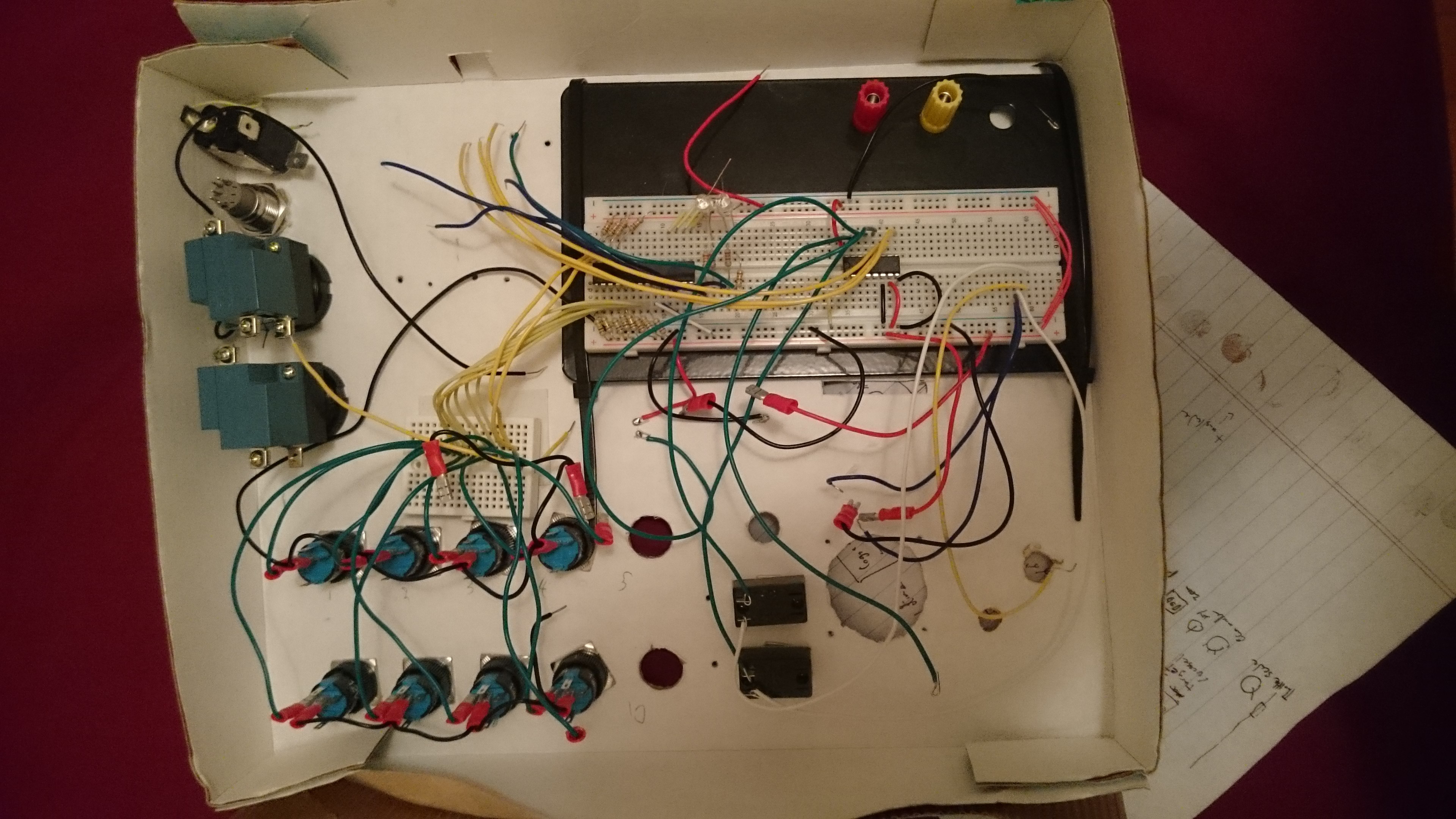
- My first try getting the code working, I just wanted to get a throttle working (that was hard enough). Then I set up an initial prototype box to start playing with layouts and also start figuring out how to use the multiplexer chips I would need:
![]()
![]()
I also started working on my part list, which let me plan out what components I needed to buy and (more importantly at this stage) how many digital and analog pins I would need for them. This let me figure out how many multiplexers were needed (lots).
Kerbal Spaceship Potato
This is an input focused control panel for Kerbal Space Program.