My Edelstaal Machinex 5
Restoration, modification and documentation of this odd little lathe/mill/grinder/etc
Restoration, modification and documentation of this odd little lathe/mill/grinder/etc
To make the experience fit your profile, pick a username and tell us what interests you.
We found and based on your interests.
collet-box-insert.fcstdCollet box insert, editable to different box dimensionsx-extension-fcstd - 31.14 kB - 12/04/2018 at 14:13 |
|
|
edelstaal-machinex5_web.pdfScanned user manualAdobe Portable Document Format - 2.67 MB - 12/01/2018 at 08:28 |
|
|
The three jaw chuck has a big opening, as big as the spindle nose, where stock can feed through. That presents a small problem, it exposes the quite delicate collet taper on the (non hardened!) spindle. Judging from some blemishes on the tapers I can tell the previous owner has accidentally hit the taper with a workpiece before so something needs to be done about this to prevent further damage.
I modified the 3d printed emergency collet model to become a simple taper sleeve, leaving as much bore as possible to feed material through without being tempted to work without it on.
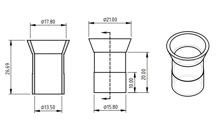
I printed these in PETG, they fit snug in the inner taper and bore, with just enough clearance to thread on the chuck.
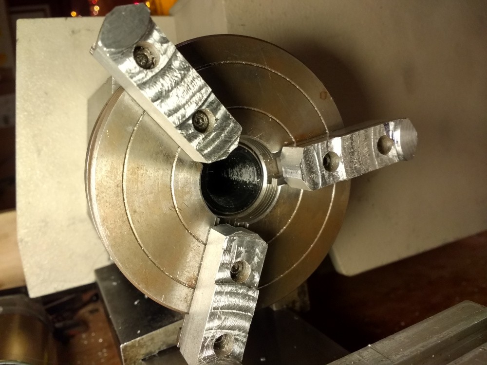
I now feel a lot safer throwing stock into the chuck without having to worry about the nose taper getting dinged.
The lathe uses a pretty nice round dovetail system to lock the top slide and mill table accessories. The dovetail is turned on the bottom of the top slide and gets inserted in a hole in the cross slide. This then gets locked with the help of a brass pin which is shaped such that it both makes a wide contact area to restrict rotation and pushes the dovetail against the cross slide for location.
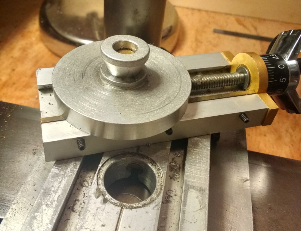
The milling table has an identical mechanism with the hole in the middle. Accessories that I have and fit the mill table are a really cute milling vise with a graduated rotating base, and a chuck holder, piece that has the same threads as the main spindle and can hold any of the standard chucks. The arrangement is very flexible.
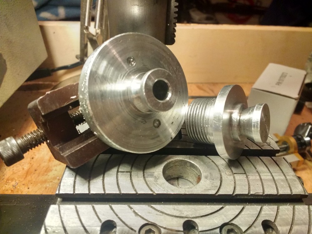
One problem though is that one of the brass pins was missing, the lathe only came with the lock for the mill table, so I could not use the top slide unless I moved the pin over to the cross slide and added a little extension, as the length is too short. I decided to just make my own pin for the cross slide instead of going through that hassle.
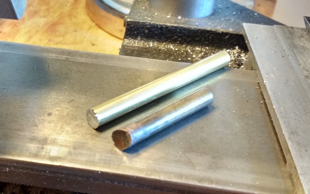
Cutting it off to the right size was the easy part, the dovetail-facing part of the pin needs to be shaped into a complex curve that intimately contacts as much of the dovetail as possible when locking, to ensure pressure is applied evenly and a good lock can be achieved without marring the soft dovetail. The ideal tool for the job would be a dovetail cutter of the exact same radius and angle as the actual dovetail; since I don't have one of those I had to improvise.
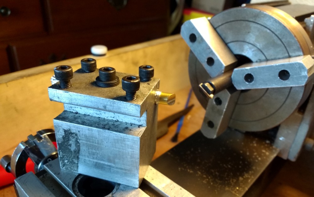
A good rough starting point was to use the boring bar in the spindle as a crude boring head, set to a radius that is about midway the cone of the dovetail, and the brass pin mounted as if it was a boring bar, with the holder angled to the dovetail angle. That produced a cylindrical profile that contacted the dovetail along two lines in the outside. I checked contact using a dry erase marker (neat low-precision replacement for engineer's blue). To generate the final shape I just iterated several times between marking up the face, rubbing against the dovetail and filing down the high spots. Here's a picture taken about halfway through the process.
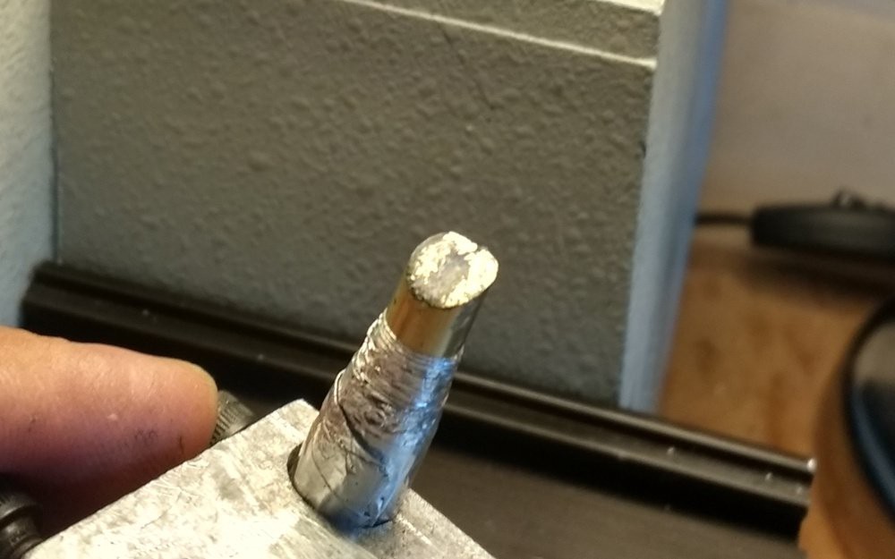
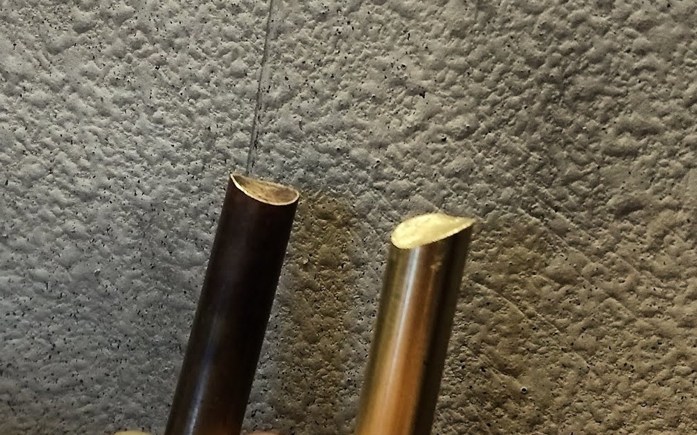
I continued until almost all the dry-erase would rub off against the dovetail, pretty close to the factory one.
Looking through ebay I found this little gizmo which is an official accessory to turn the lathe into the cutest little bench grinder. It consists of a steel arbor and an extruded aluminum guard. The arbor threads directly into the spindle nose and can clamp a 1/2" ID, 3" OD, 1/2" thick grinding wheel. The guard is very hefty, it appears they reused the same profile used in their steady rest (which I don't have) with a couple more very heavy gauge sheet metal parts and a plastic window to complete the assembly.
This is what it looks like mounted on the lathe:
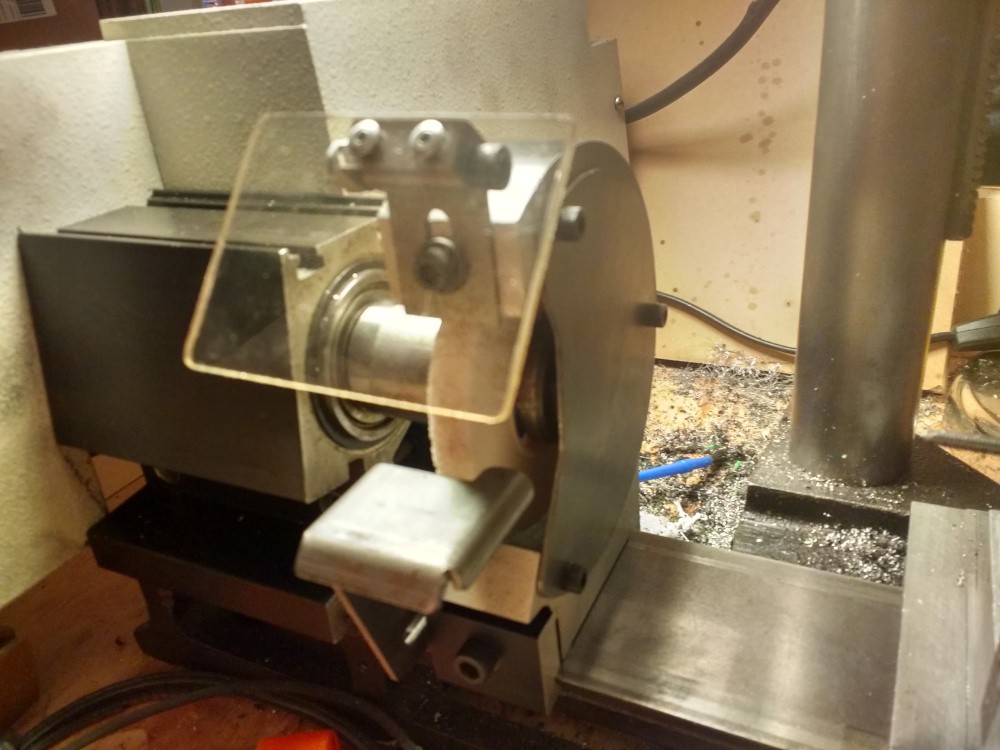
Grinding on the lathe is probably not the best idea if I want it to last another 40 years, but I don't plan to use this much, and it will come in handy.
While measuring the collets for the collet box build I had this silly idea; why not attempt to measure them as accurately as possible, and then make a 3d printed blank "emergency" collet? Plastic collet blanks are available so this is not a totally insane idea.
I measured the critical dimensions as best as I could with my calipers and put it in a FreeCAD model (dimensions in mm)
The dimension I'm the most unsure about is the included angle of the taper, it does look symmetrical, and it does seem to be 41 degrees, but it is hard to measure accurately with my current tooling. I 3D printed a few copies of that model in PETG and tried it out on the spindle.
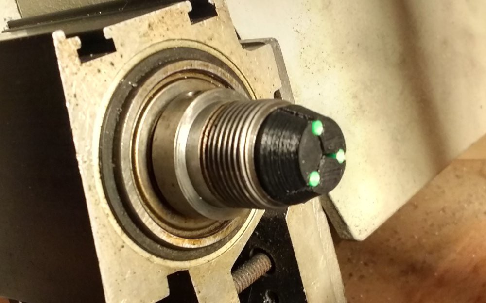 It seemed to fit fairly well. If you're wondering what those green dots are, they are pins made of 3mm filament (ABS I think) inside some recesses I modeled in the collet "jaws" to prop them open for machining, otherwise they would be collapsed by the nut and not be able to close any more than the machined dimension when in use.
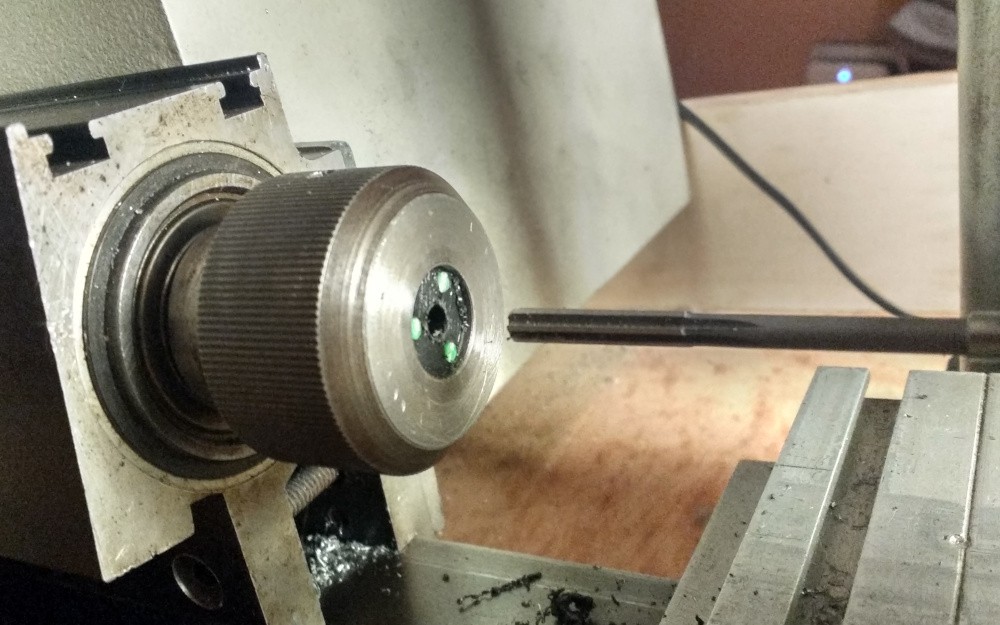
Then I did a quick test with a drill and 6mm reamer. It would have been better if I had actually bored the hole instead of reaming, as the reamer can wiggle and not make a perfectly concentric hole, but I didn't have the right boring bar at the time.
The lathe came with a set of 8 collets, from 1/16" to 1/2" in 1/16" steps. They came wrapped individually in little plastic tubes, well protected but impractical to use. I had this little wooden box laying around that proved perfect for holding the set for easy access.

The box came with the partition in the middle, I designed some 3d printed inserts in FreeCAD (fcstd in the project files)
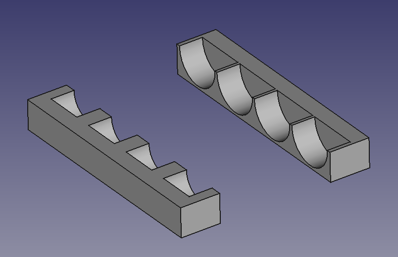 They are just held by friction, some cushioning foam on the top ensures they don't rattle around.
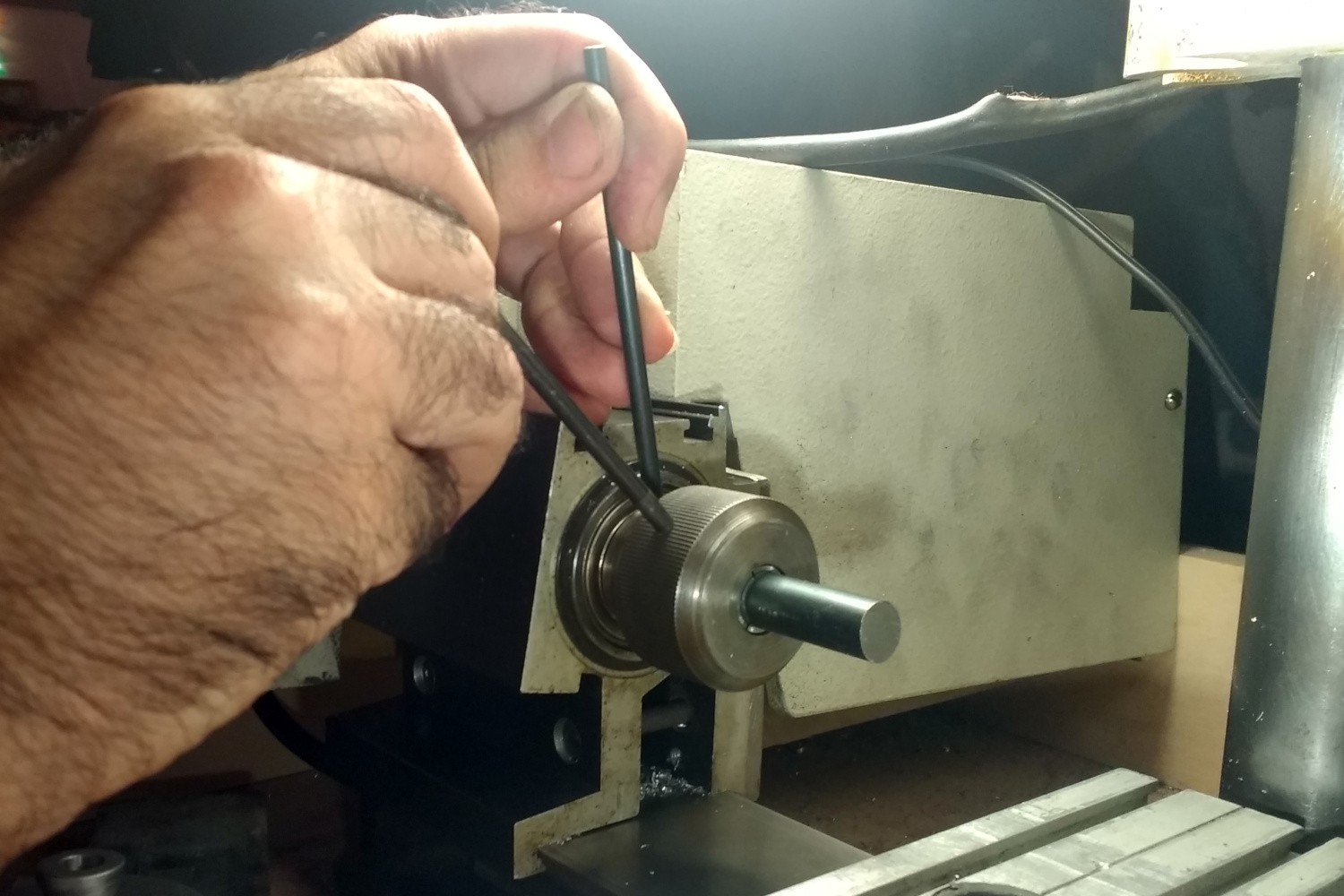
Both the lathe spindle and collet nut have a 5/32" hole to accept a "tommy" bar for extra torque when tightening/loosening collets and chucks. The 3 jaw self centering chuck came with a single tommy bar that is 3/16" in diameter. Since I like multi-purpose tools, I turned down the last bit of the diameter on 2 small 3/16" rods to 5/32 like so
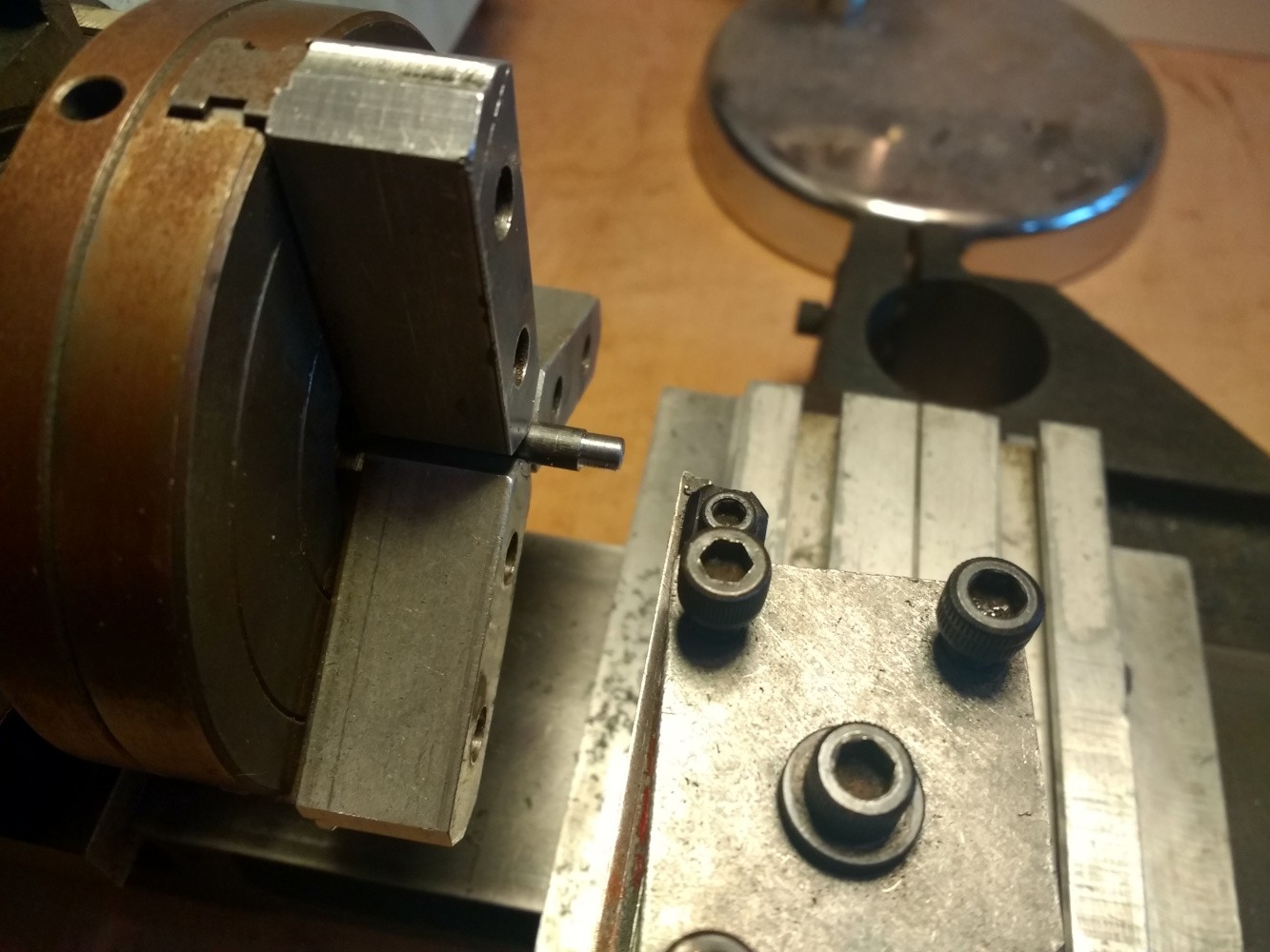
Notice the awesome concentricity, I've got to resurface those jaws...
Obligatory action shot:
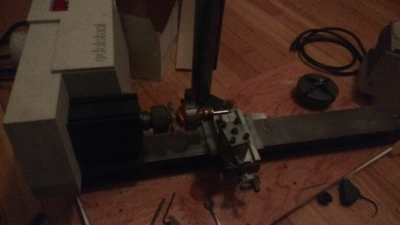
The lathe arrived home very well packaged, opening all those boxes inside of other boxes that contained the different parts of the machine was like Christmas. I could not contain myself, I had to make some chips. So I proceeded to haphazardly put all the main parts together on the floor and flipped the switch on.
After I had my 15 minutes of fun it was time to take it all back apart in order to give it the maintenance it deserves. First issue I noticed was a rubbing sound coming from the headstock, after looking carefully I found that the axle that holds the intermediate pulleys between the motor and the spindle were severely crooked.
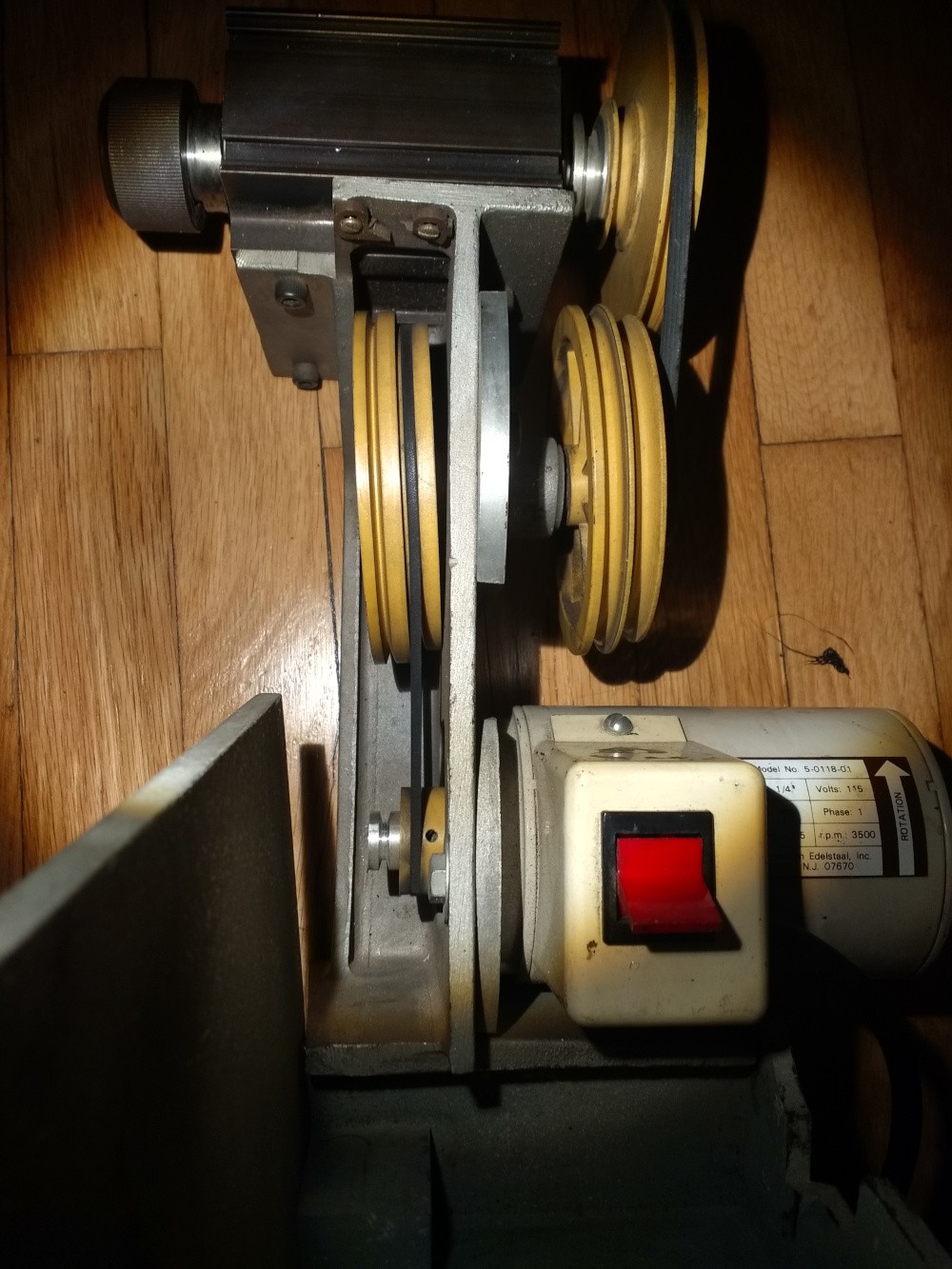
I rotated the pulley by hand and to my relief, the shaft was not bent, the pulleys stayed at the same angle during the entire revolution. I took the thing apart and I found the usual suspect.
The sleeve bearings were worn almost through, the holes severely deformed into egg shapes. Luckily these bushings are a standard part, "Oilite" plain bearings for 3/8" shaft, 1/2" bore and 1/2" long. The installed bearing had a flange 5/8" in diameter, but I saw that the counterbore in the casting could accept a larger flange, so I bought a few with a 11/16" flange from McMaster Carr, part number 6338k415. The old bearings came out pretty easily when persuaded by a pair of channel lock pliers
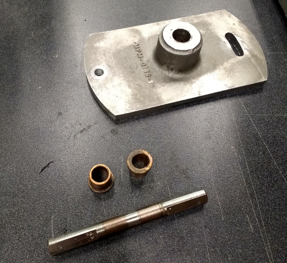
I also polished the shaft, which got a bit grooved from the wear, but cleaned up reasonably well. The new bushings went in almost a bit too easy, but ended up solid in place.
Another little detail on the assembly was a pair of Oilite thrust washers between each pulley and their corresponding sleeve bearing, I'm not sure having both bearing sides be sintered bronze is the best idea from a durability standpoint, it is usually best when you have a hard material like steel bearing on the bronze with the oil film in between. Since the spacing was needed to keep the pulleys aligned I lapped a pair of steel washers flat so that they would have a flat and even bearing surface against the flange of the bushing.
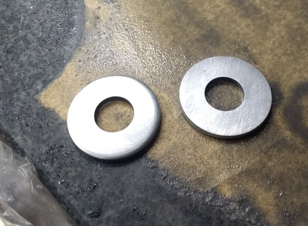
It all runs nicely when spun in the bearing holder, but when trying to assemble the entire thing I found that the pulleys don't align correctly with one washer at either side, it did seem strange when I disassembled this both Oilite washers were only on the motor side of the axle. I think this will call for custom spacers later on, but I need a running spindle for that! This will do for now.
Create an account to leave a comment. Already have an account? Log In.
Love this page. We recently found an Edelstaal in a storage facility. Its in pretty good shape, but the belts need to be replaced. Have you found a source for these?
I know this is a fairly old project, so I'm not sure if you're still working with the Machinex5, but I've recently acquired one myself and I was wondering if you ever came across any other documentation for it? Like the accessory catalog, or any magazine articles discussing its use? I know there is an article in The Home Shop Machinist from 1982 for instance. So interesting that it is nearly impossible to find parts or even other users who own these machines! As if only 10 machines were made, haha.
Ha! I have one of those bench grinder attachments too!!! Never used it. It was just to easy to walk over to the real bench grinder and hit on.
Measuring angles can be a real pain. I had a few V bits and was not 100% sure what the angle of the V was. Some were 5 degree, some 8 degree, 10 and 15 etc.. I found a great little iphone app that uses the camera and has a protractor built in. worked prety well and was a little easier than taking a photo from above then putting it in to Fusion360 and laying lines over the top to get the angles. :)
Not a bad idea, I'll have to give something like that a go. A phone camera may not be more accurate than what I've measured (my uncertainty right now is "just" a couple degrees)
Become a member to follow this project and never miss any updates
 Paul McClay

 Tina Belmont
 matthewkleinmann
I happen to have a 24" version of this lathe. It's apparently an early 1 as the tailstock ram isn't threaded. Mine didn't come with the vertical column, nor motor. I might consider selling it or individual parts from the machine (have 2 chucks also). You can email if interested ( remove the "9"s first skog99kat007@yahoo99.com