Close
0%
0%

Minamil 3dp: another minimal CNC mill

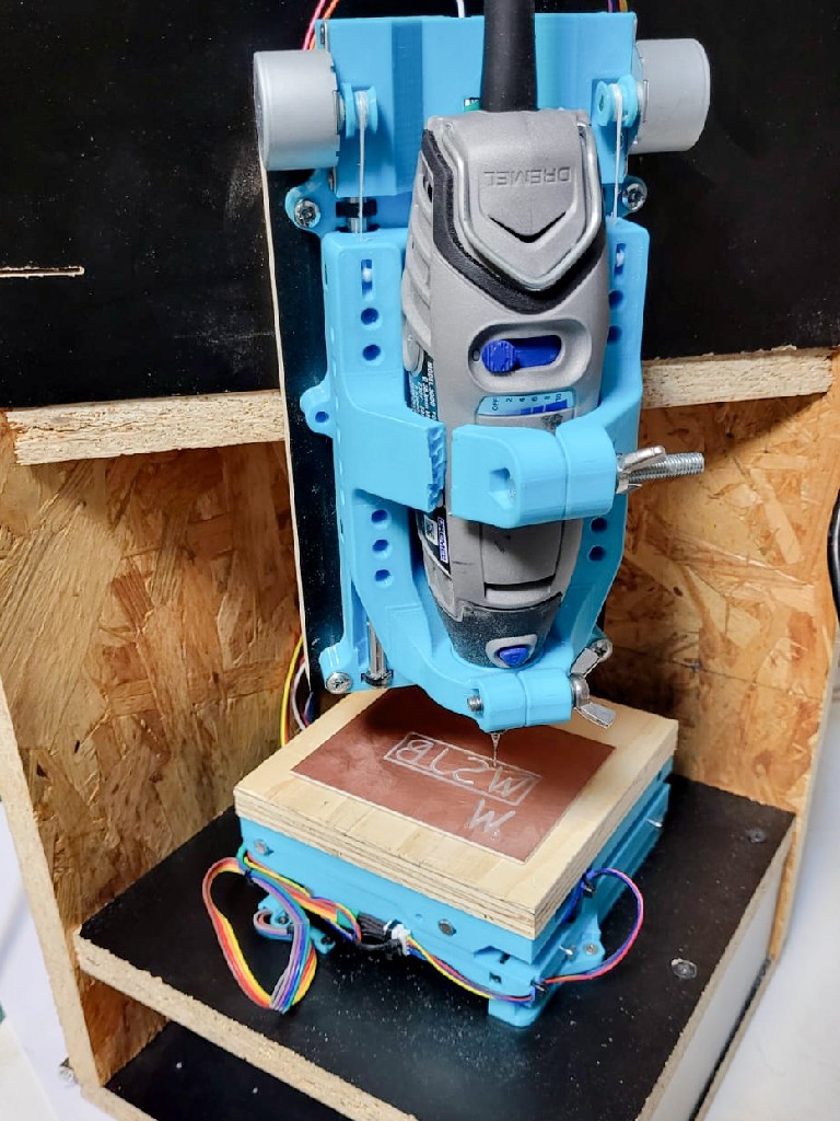
A very compact, very inexpensive, very DIYable, very precise little CNC mill. This one uses 3d printed parts.

Public Chat
Similar projects worth following
"MInamil" -- this time it's "Minamil 3dp" because 3d printed -- is a minimal CNC mill that actually works pretty well. It's small and it's not strong, but it's uncommonly precise for an amateur-accessible machine. Small is a feature, and light cuts with small cutters gets stuff done with available strength and stiffness. Work volume 75 mm x 75 mm x 50 mm.

(16 Sep '24 update: replace 0.2 mm trace example with 0.1 mm)


Hackaday Prize 2023 finalist! Thank you judges!


Minamil 3dp is another little CNC mill. This one uses 3d printed parts, which give (at least) two advantages:

  • probably more people can 3d print parts today than can laser cut parts
  • much easier assembly vs. building 3d structure from 2d parts

While not at all necessary to make the CNC parts work, a little more work put into the frame/enclosure can make a more practically usable result. The example shown below also shows:

  • a completely new configuration of the integrated enclosure concept relative to earlier work
  • more complete actual accomplished integration of accessory stuff that could be integrated but previously wasn't

And a little side show that makes this work, that I haven't seen elsewhere, and that might help anyone trying to do fine work with a cheap rotary tool: reducing runout.


Cut small stuff from useful materials:

Up to 75mm x 75mm x 50mm.

Figure cut from brass flat bar using 1 mm (0.039") and 0.015" (0.38 mm) flat endmills.

nevermind the paint -- that's a different learning curve.

...and yes, I will mix units horribly in this project. it will be ok, we're not trying to land on another planet.
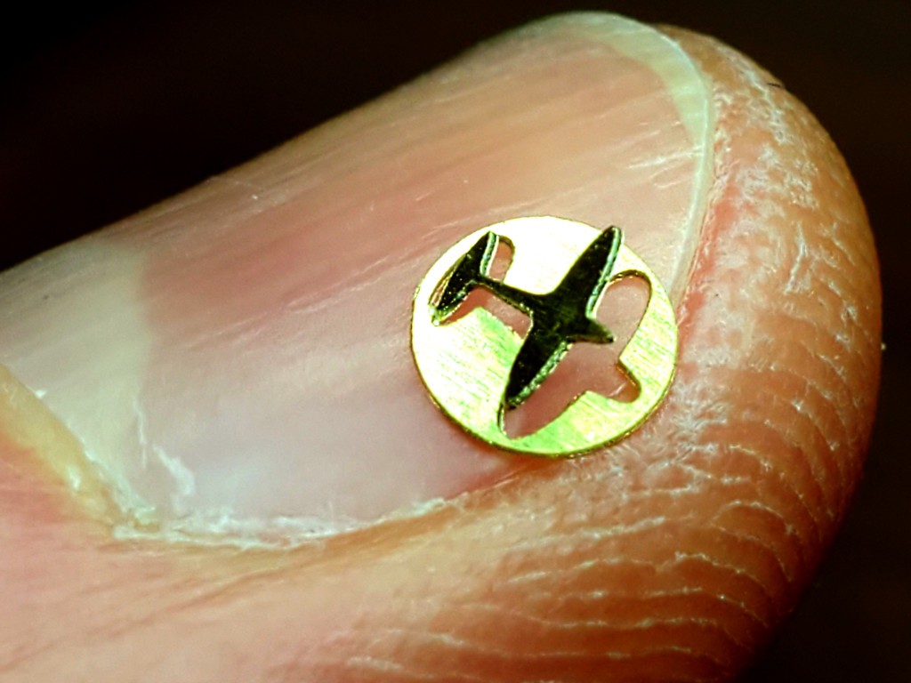

Little airplane in a 4 mm disk cut from brass shim stock with a 0.1 mm V bit.
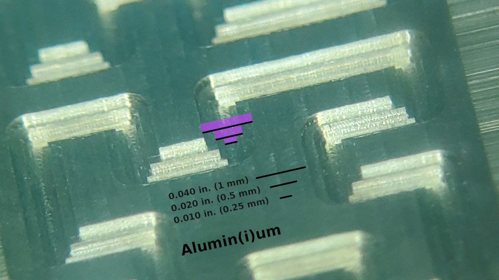

Sharp, accurate features in Aluminum with tiny cutters down to 0.010" (0.25 mm). This pic is a backlash test pattern for the "big" cutter that I repeated with the smaller cutters because new toys.

This short video is kinda neat but doesn't really add much so I'll link instead of embed so hopefully it won't slow down your first scroll through this stuff:


Mill circuit boards for fine-pitch components:
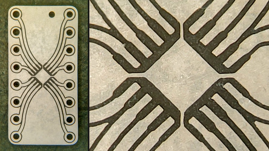
Breakout board for 0.5mm pitch QFN-16. 
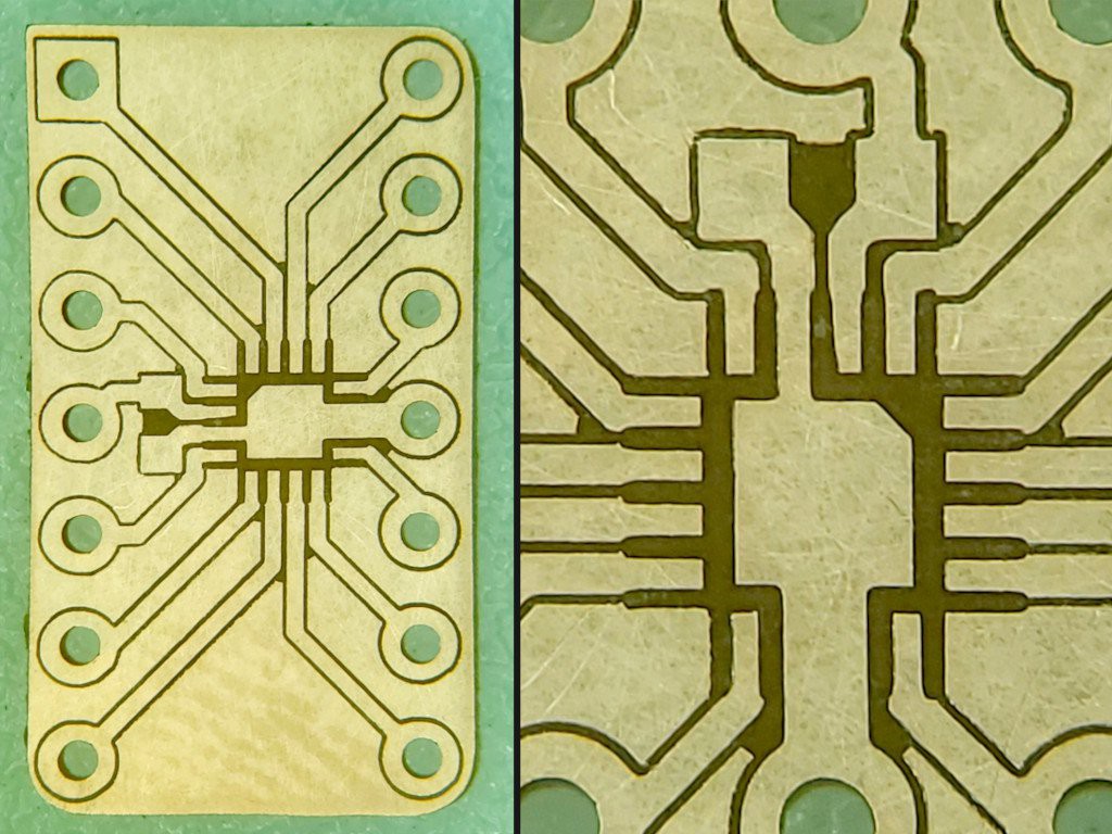
A more specific 0.5 mm pitch QFN-16 breakout for TLV7044 with supply bypass closer to the chip and pinning like the DIP & SO packaged parts. For a different project. Hopefully I'll be able to replace this pic with a populated board "soon"...
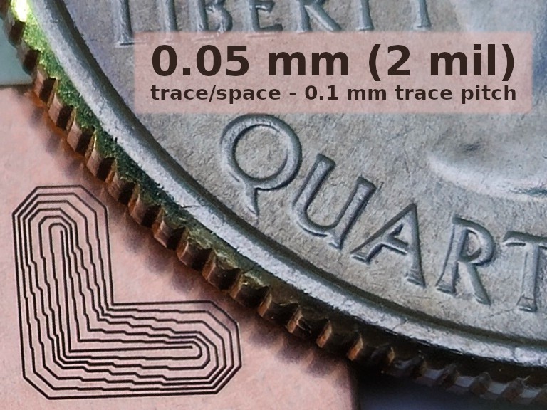
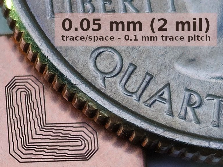
Isolated copper traces down to 0.1 mm center-center pitch with a massaged "0.1 mm" V bit.


But that's all flat stuff :-/

Yeah. I've been working on the tool instead of making stuff. But check this out:

First I'll show this little bevel gear,...
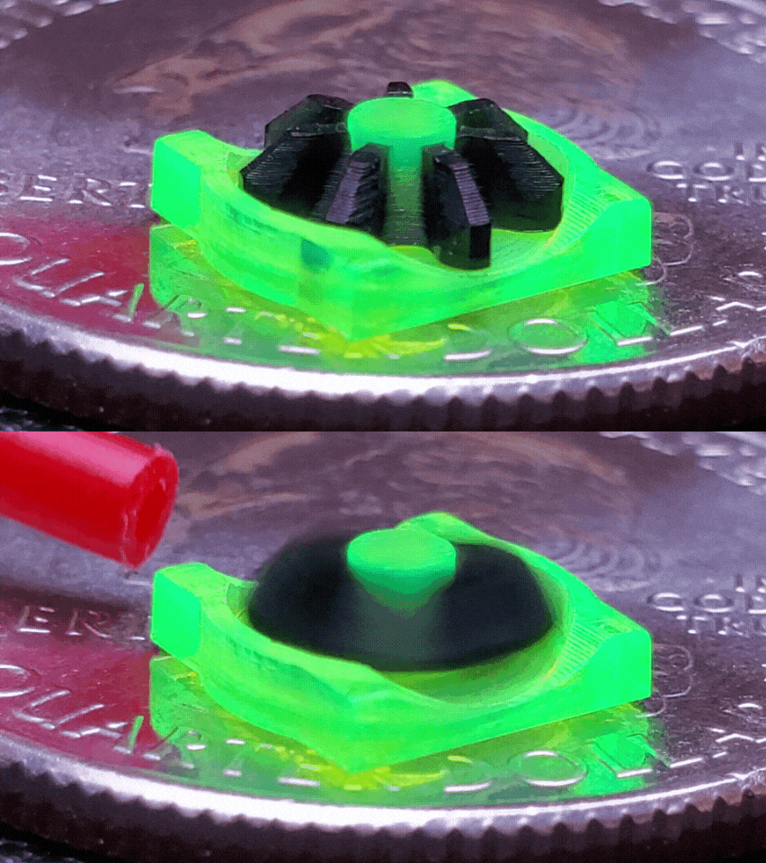
... because the "3dp" 3d printed mill that is the object of this project actually for real cut that gear at MRRF. So I hope you'll accept some parts cut by the earlier laser-cut version of this CNC as an illustration of capability:
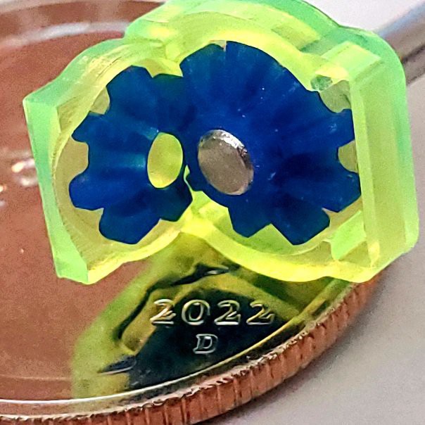
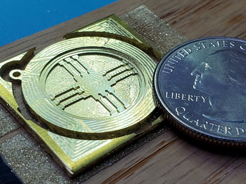
Spider gears and structure parts for a little differential with a US "quarter" coin for scale.
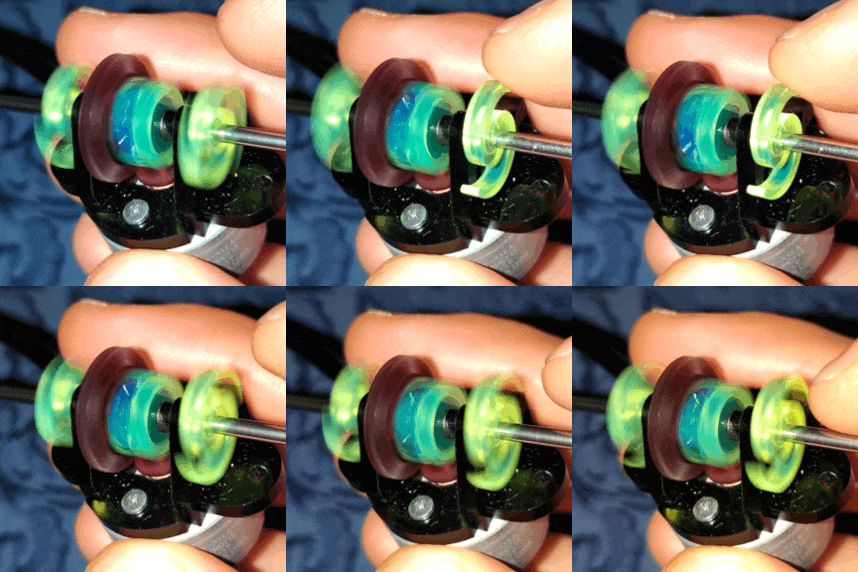
The spider gear assembly in the complete differential is smaller than my fingernail. There's a <4 min. video about that over in the "2dc" project but it's old work and too much about the earlier laser-cut design to include in this project.


Packaging for UX

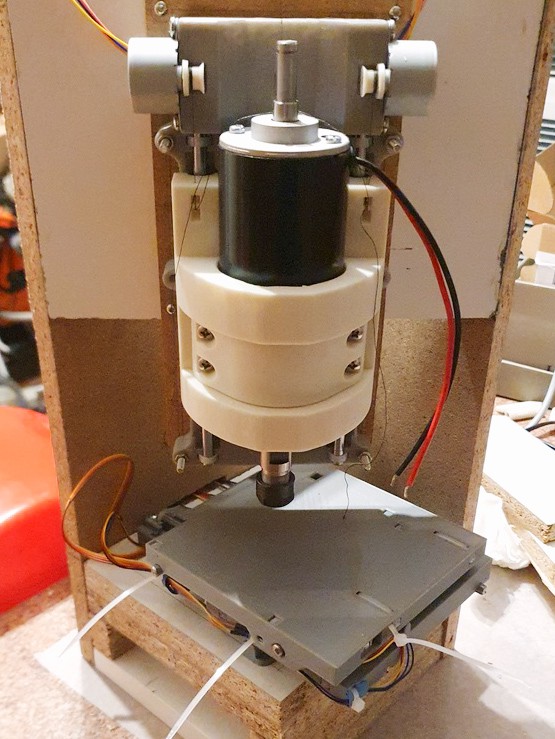
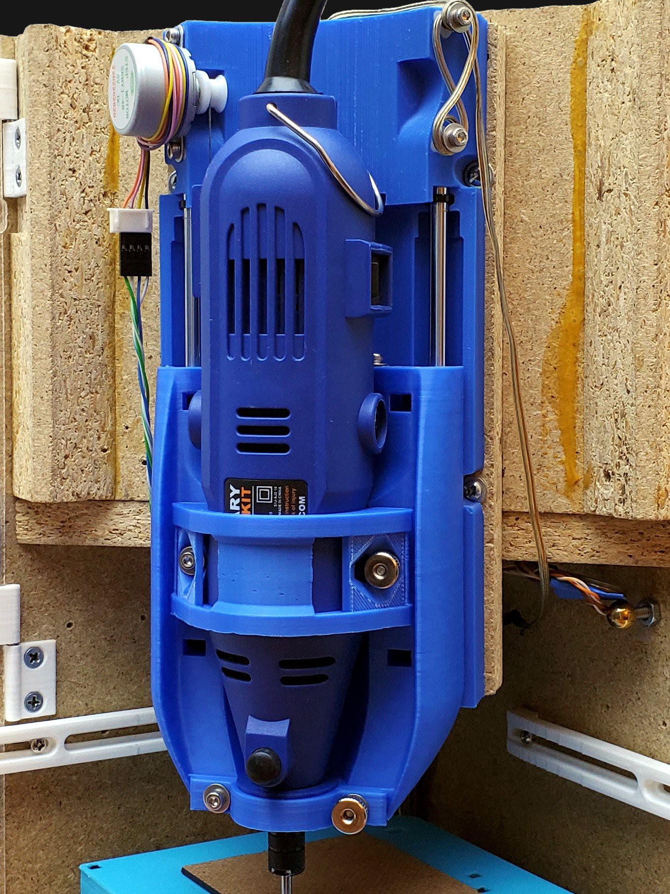
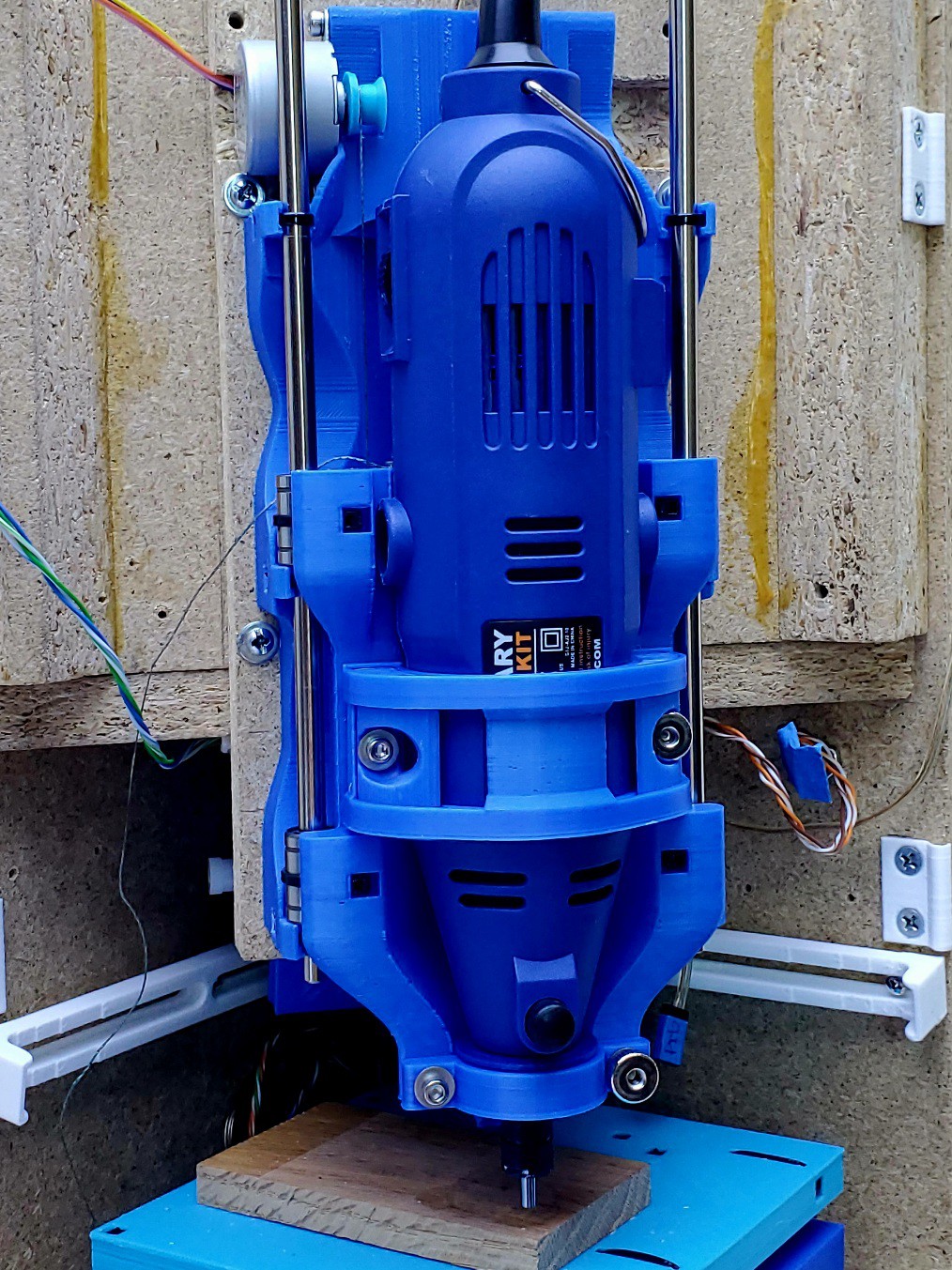
The CNC mechanics consist of an XY table and a separate Z axis. The two parts need some sort of frame to hold their positions relative to each other. The frame can be very basic. But I want to use my machine in a smallish urban condo with no "shop"-like space.  So I've put a little more effort into the frame and packaging..

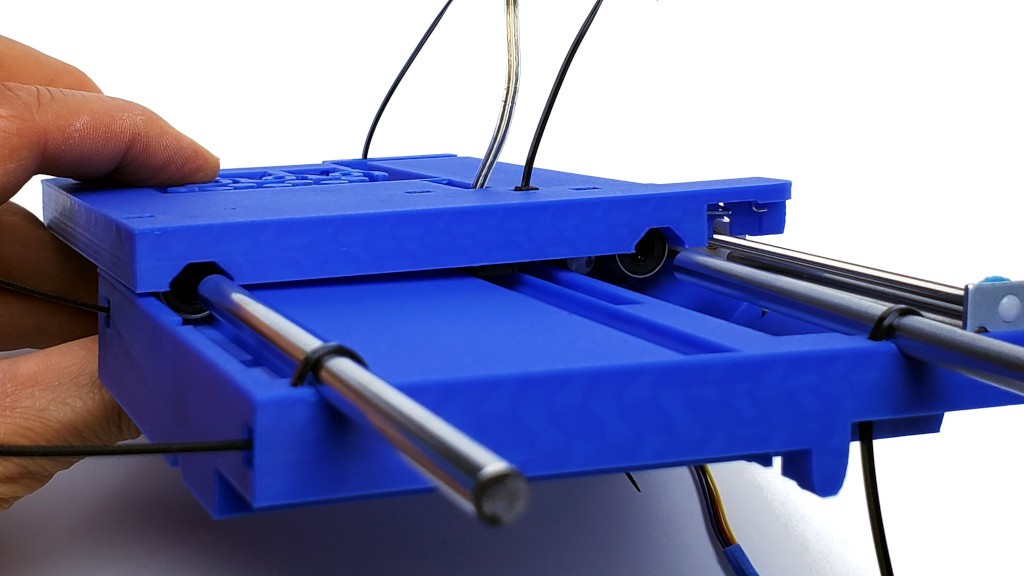
The "telescoping" slide design allows very compact non-operating footprint.
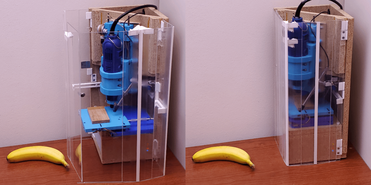
More about packaging -- which is already obsolete because I haven't yet written up several improvements like cleaner DC supply and integrated logic-switched AC for the dremeloid.


Interested?

To build your own, start here.

To scan log entries, ToC here.


Spun off from #Minamil: a minimal CNC mill and companion to #"Desk Accessory" CNC Milling Machine.

This project encompasses 2 projects. And a half.

  • very small and low cost 3-axis CNC mill/router mechanics
  • #"Desk...
Read more »

minamil3dp-Z-STLs-v0.1.0.zip

Z axis parts.

Zip Archive - 1.06 MB - 09/25/2023 at 20:41

Download

minamil3dp-XY-STLs-v0.9.1.zip

X+Y stage parts. For slicing info see https://hackaday.io/project/192074/log/223146/

Zip Archive - 6.71 MB - 09/24/2023 at 07:33

Download

  • One minute video

    Paul McClay01/15/2025 at 22:23 0 comments

    A while back I made a few videos to show some of what's easier shown than said. Or believed. Since then I've: shed the Z counterweight, shifted from laser cut to 3d print construction, and changed the frame among other less visible changes. But I haven't made any new widget as photogenic as a little gearbox to prompt a new eye candy vid.

    So here's one minute of simple but sharp recent work with 3d printed mechanics in the current iteration of fancy package:


    I'll probably lift some tight shots from earlier videos eventually, when there's more of more recent content to mix it into. Just replacing wide shots of old stuff with wide shots of new stuff could be expedient, but then "... and here's a different machine that didn't do any of that but could have believemeIpromise" would be awkward.

  • FR-2 = "wood" for very fine detail

    Paul McClay01/13/2025 at 22:33 0 comments

    ...and tough too!


    In the previous entry about contacting local scale model builders to ask if they might appreciate an accessible little CNC machine, I mentioned a couple tries at making a "trail board" for a Midwest Model Shipwrights member.


    People have been making scaled-down models of inconveniently large things for a long time ... and I've abandoned hope of summarizing that in a sentence. Making detailed wooden models of wooden ships stands a little aside from the model-making mainstream as we approach the 21st mid-century AD, but the venerable practice persists and practitioners gather nearby.

    Wood has grain. Scaling down wooden parts has the effect of scaling up the wood's grain. Very fine grain woods mitigate that with good success well established[1]. But trying to capture finer detail at smaller scale eventually turns into trying to carve a tea set from a stack of sewer pipe.

    From last time:  

    • I wrote about FR2 exceeding expectations as a machinable material not entirely completely unrelated to wood but with essentially no grain. "FR2" is an imprecise term for the brown resin-saturated paper board used for the cheapest, simplest circuit boards.[2] Similar material is available by other names. Contrast with FR4 which is glass fiber+epoxy and hostile stuff to work with. I'm thinking this paper+phenolic stuff looks promising for compatibility with wood model construction, but that remains untested by actual model builders -- that I know of. But maybe I'm just the last guy to get the clue. Some "phenolic paper" material is advertised for "enhanced" or "finest" machinability. "FR" = flame retardant.
    • I had started off in the wrong direction with the first couple of whacks at the "trail board" example. Further information clarifies that what look like scrollwork borders of a flat board appear straight only in profile. The ornamented part is parallel with the mid-plane so it can be taken directly from the drawing. And the builder already has the structure and only needs the decoration.

    So, back to the drawing board.

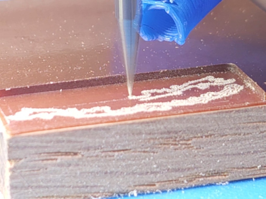
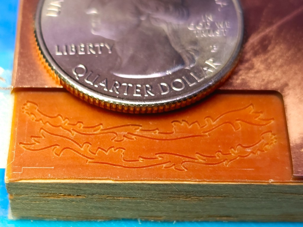
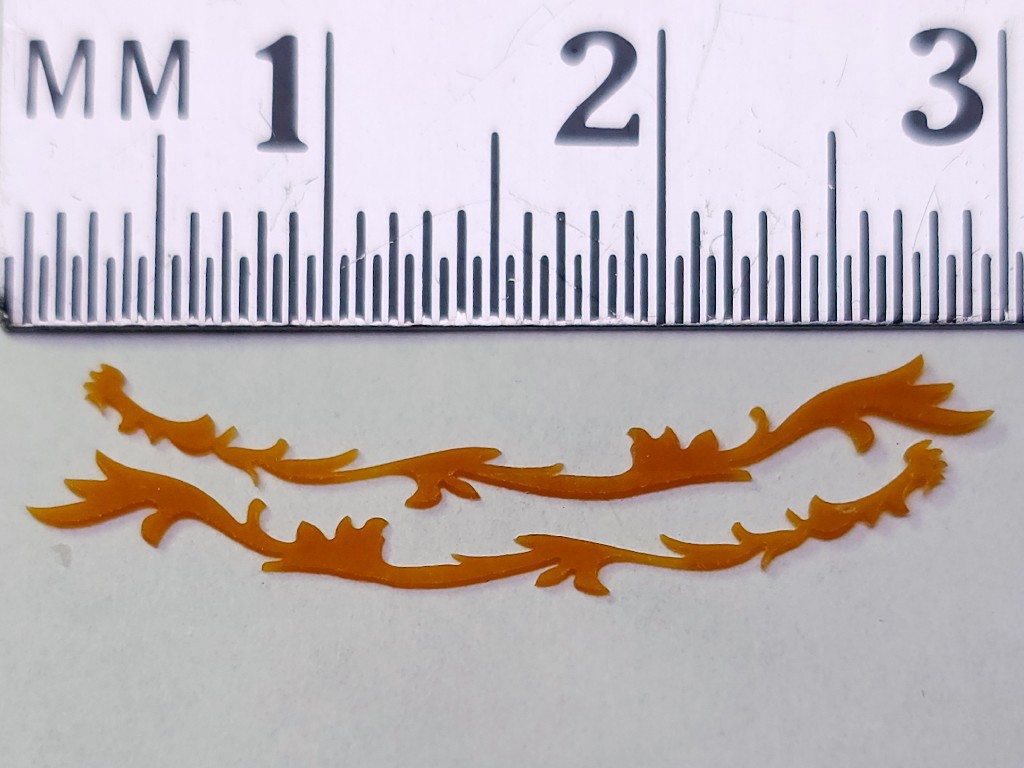
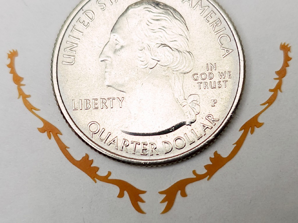
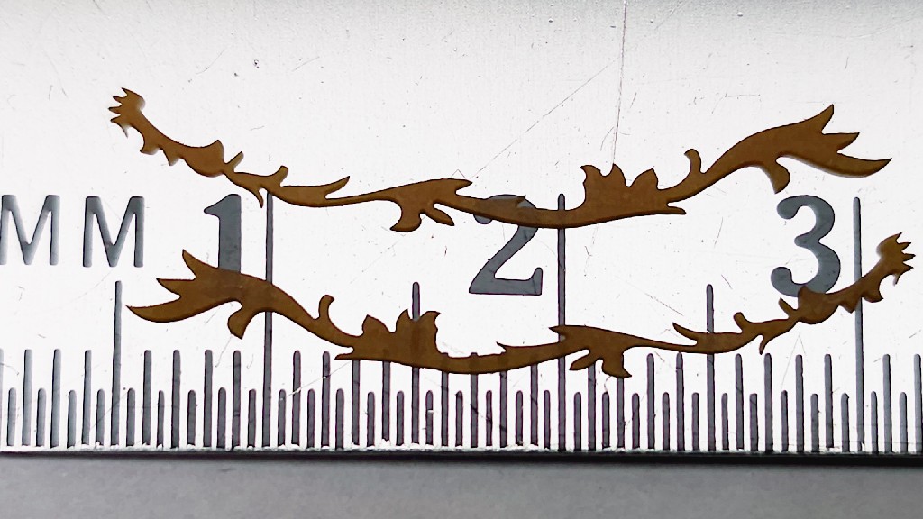
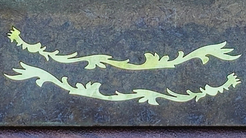
    Then milled a patch of FR2 down to 0.3 mm thick (or so I thought, but it came out more like 0.34mm -- dunno why) and from that cut out a mirrored pair of figures using a 20°, 0.1mm Vbit. I didn't feel like testing how deep it could cut without breaking the tip or deflecting when I really wanted the best narrow cut and sharp inside corners, so I ran six passes at very conservative ~0.05mm steps down ("~" because a little more to match four Z motor half-steps). I expected that to cut through or very nearly so. But it didn't. So I ran a few more half-steps down until the bottom of the cut looked different. I was complicating this for myself by trying to cut no deeper than necessary because deeper makes the V cut wider. 

    When I peeled that up it turned out of that I still hadn't cut through. My current guess is that maybe the glossy surface layer has a different consistency so the top of the bottom skin looks different, but I don't know. In any case, that was initially disappointing. Then I tried sanding the remaining thickness off the uncut side, and that worked quite well.


    Some beauty shots:

    That's a half-millimeter scale. (labeled "MM" in CAPS and numbered by cm. :-/ )

    Check out how thin the thin parts are! Earlier I didn't have any great ideas for how to avoid bending that if made from something like brass or styrene, or breaking it if possibly something like that could be cut from boxwood (which I have yet to try). That's where the FR2 works great. Not only is it possible to make those, but also to handle them. They are, of course, fragile. But so far I've been able to handle them "carefully", in the ordinary sense of "careful".


    I gather that a chronic challenge / mark of skill among model builders is matching reflected pairs of parts or features like this. To demonstrate...

    Read more »

  • Thumbnails are the windows to ... scale modeling

    Paul McClay11/25/2024 at 01:06 0 comments

    Log backlog got big again...


    I've been plugging away at making little CNC machines and writing about it. And making little things, few of which have much use apart from tinkering with the thing-making machine. Earlier  ̶t̶h̶i̶s̶ last year I randomly discovered that there are several scale modeling clubs around here, including the Midwest Model Shipwrights. Might people who actually make little things have some interest in actually using a little CNC to make actual little things for the thing they do?

    Now, these Model Shipwrights are very good at making the things that they already make. And they already make all the things that they need to make model ships. And they know a lot about making model ships. Viz:

    orgforumjournal
    Nautical Research GuildModel Ship WorldNautical Research Journal
    ISSN 0738-7245
    Ships of ScaleShips of ScaleThe MSB Journal
    ISSN 1913-6943

    There are journals. With ISSNs. Not just one.

    So I'm not going to tell these people how to model ships.


    ...


    But I ventured to show up at a meeting with some example widgets and asked if making such things seemed like an interesting capability, and what sorts of ship model things might be interesting to make differently with a different tool.

    That went well enough to gain an invitation to return, some examples of things to try, and some material samples.

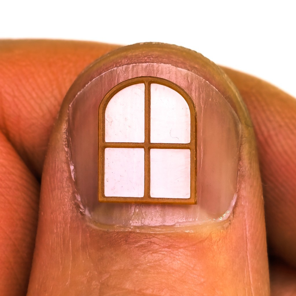
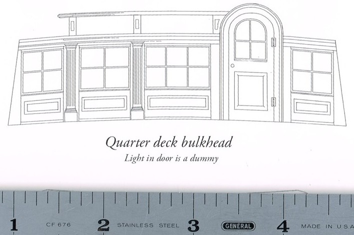
    Things to try that might prove interesting included a drawing of window frames, which "usually present a challenge for modelers":

    That's where the window in my thumb comes from. We'll get back to that...


    This post grew long before it got to the end that I had in mind at the start. It's mostly but not entirely about little windows. If I'm saying this is doable, I probably should show at least one example of process from idea to result. That said, this is more an illustration of how some ideas evolved when the tool at hand was a little CNC mill and not so much a tutorial for CAD or CAM or steps to replicate this result.


    Show > Tell: What useful work could a little CNC do for a modeler of ships?

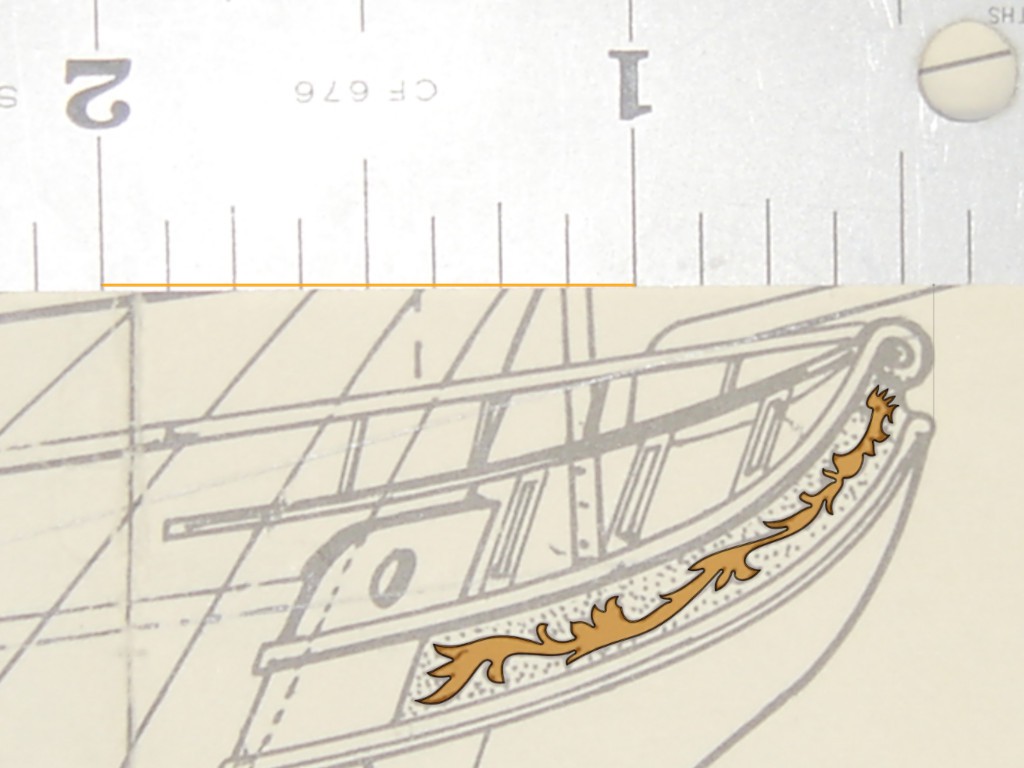
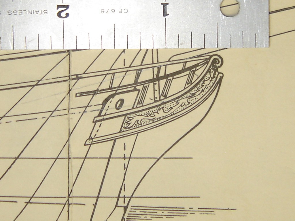
    The first example I tackled was this "trail board" -- one of the pair of decorated boards that sometimes dress up the pointy (or blunt*) end of a ship.

    The trail board, which I understood to be flat, looks like it runs from the stem back to a point where the hull has some breadth. I guessed that it might be oriented something like the blue and gold trail board on this model:

    source: Roland's Ship Building Blog (that part is pewter, and so maybe a candidate for milling instead)

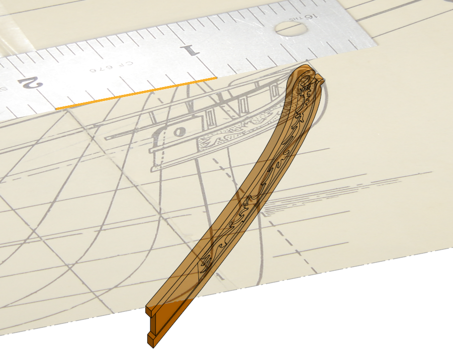
    Supposing so, then the profile drawing shows a projection of the board leaving two degrees of rotation to determine the correct shape. In between me asking for, and the builder of that model sending another view, he described the boards in a vertical plane. So that's down to one rotation. A first proof of concept demonstrator doesn't have to be actually correct, so I guessed and projected from the drawing to make a solid model. The yellow inch ties model scale to the drawing.

    (wrong first guess -- later this will get corrected)

    While the ornamental figure has a convoluted outline, it appears essentially flat in the drawing. Maybe the prototype was more viney/leafy and maybe a larger scale drawing would show that. For a first whack, it's convenient to believe that it really is supposed to be flat and extrude the traced figure into a "2.5"D solid.

    First articles: port & starboard figures cut from 0.001" brass glued to a chip of hardboard. 

    Sharp inside corners were the main challenge. These parts were received as good enough to validate the idea; next try could be sharper. In part because the underlying surface could be more nearly level -- note left end of the upper part vs right end of the lower part.

    aside:                                         ...
    Read more »

  • circuit milling: 0.05 mm (2 mil) trace/space

    Paul McClay09/13/2024 at 05:10 0 comments

    Last year 0.2 mm trace pitch seemed pretty tight:

    "... just think of the precision required to take off the copper layer and only the copper layer, and leave traces down to 0.2 mm behind." -- HaD Prize 2023 finalist announcement

    Here's half that...

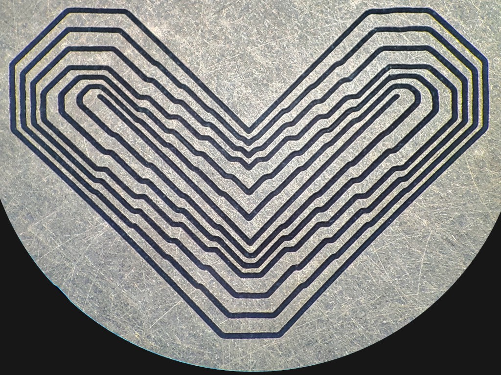
    isolated copper traces from 0.2 mm to 0.1 mm center-to-center in 0.025 mm steps

    Admittedly more tedious than $pendier option$ with a big friendly START button, but this little machine got the job done.

    detail view rotated 135°ccw before writing anything which makes writing hard: X bottom-right to top-left; Y top-right to bottom-left; horizontal/vertical <--> diagonal; I could de-rotate but describing features doesn't actually get much easier unless with a labeled diagram and that's a rabbit hole I'm trying to not go down today...
    • From counting pixels[1] and a little more math than expected[2], I figure the 0.1 mm center-to-center traces (the skinny ones) are 46% trace and 54% space. So 0.046 mm trace and 0.054 mm space. Not 0.050 but both round to 0.05 so I'll go ahead and plant that flag. In barleycorn units: 1.8 mil trace and 2.1 mil space out of 3.9 mil pitch, and again I'll conveniently round to 2 mil trace/space of 4 mil pitch.
    • I have to stop thinking about how to interpret the various irregularities -- maybe that will be another log entry later. For example, the horizontal segments at top-left (which are diagonal) are straight but the similar horizontal (diagonal) segments at top-right are wavy. Both were cut by moving in the same direction at the same rate. The segments on the right were the first in their loops where the bit plunged at their left (in that pic), moved not-so-straight to the right, then continued clockwise. The 2nd and 4th of those (down from top) were approached from about the same direction and have about the same kink. The same segments came out better when cut with ~30 μm (~1 mil) more backlash in Y (found and fixed before cutting the example shown). The "vertical" (diagonal) segments at the left look generally straight but a little more rough than the rest -- those came out worse when cut with a little more backlash in Y. It looks like the cut path deflects a few tenths (of a mil) to the left relative to travel. Etc.
    • But mostly: hey look at that! Not "just barely" but actually pretty decent. Another increment of exceeding already much exceeded expectations for this extremely low cost, extremely compact CNC design. !.

    did he say "tedious"?

    Yeah. It was a development exercise. Lessons learned may help make future work at this scale less tedious, but probably not not tedious.

    how

    You're already reading this project about how to build a little CNC mill. Elements of coaxing the built thing to carve tiny isolation lines through copper cladding include,

    • stable hands-free magnification
    • design to X/Y stepper full steps
    • repeat to refine
      • pointy v-bits
      • runout
      • density test cuts
    • repeat to refine
      • level
      • level test cuts
    • laps

    stable hands-free magnification

    This time I went straight for the stereo microscope because not needing one wasn't an objective. I've also used my phone on a little tripod for nearly no (incremental) cost, and a USB camera for le$$ than the microscope, either of which might have adequately supported this exercise.


    design to X/Y steppers' full steps

    The small steps in the least-stepped segments adjacent to straight segments match the 0.025 mm practical limit of horizontal positioning for the motor+screw units used here. (The little jog segment length is step×√2 for diagonals (pic at 45°).) That step-over distance corresponds to one full motor step. I'm running x8 microstepping for best acceleration & speed (another log entry "soon"...) but single microsteps are so uneven that there's no fraction of a 0.025 mm step cycle that's useful for positioning. Designing to a 0.025mm "snap grid" puts each feature at the same phase in the microstep cycle for each motor....

    Read more »

  • Newer Z is gooder

    Paul McClay07/03/2024 at 04:08 0 comments

    The first Z axis was ... good enough to not fuss with for a while while fussing with the X+Y axes. The second try (i.e. first attempt to improve) was meh. This one came out better.

    The moving part & clamp changed more than the fixed part. I'll have to decide whether to make the next one slimmer or make the base plate behind it wider.


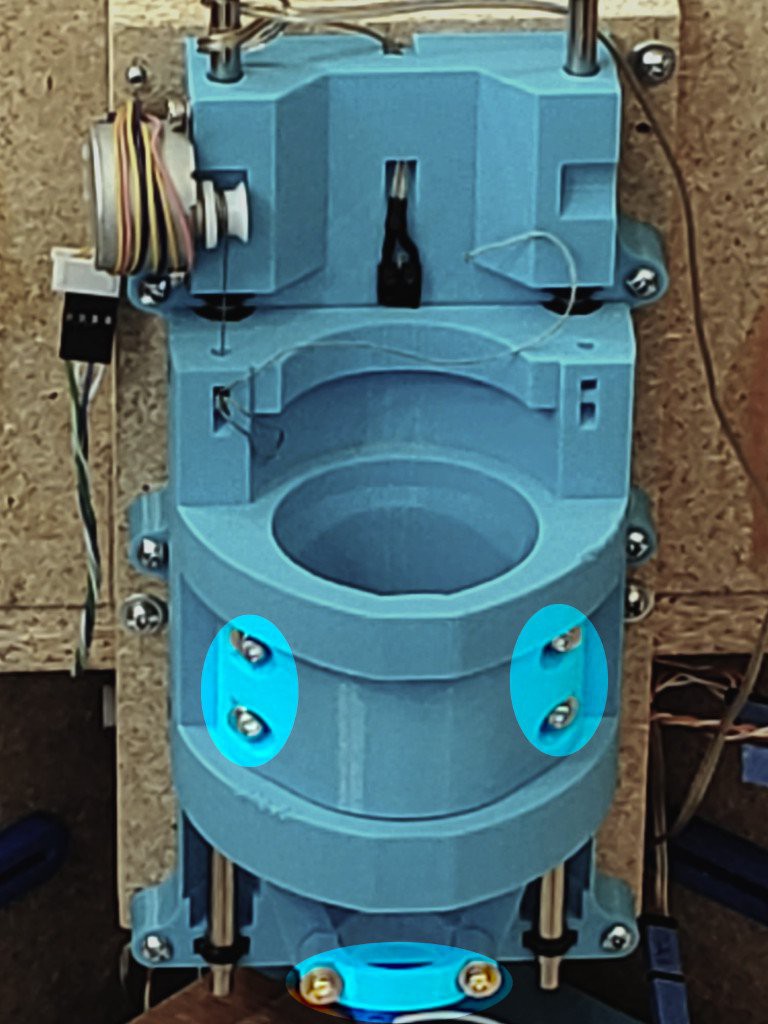
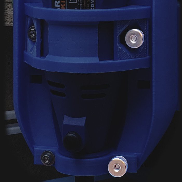
    The most visible intent/reality gap with the first 3d printed (vs. 2d laser-cut) Z axis was the fiddly half-dozen M3 socket head screws in the tool clamp.

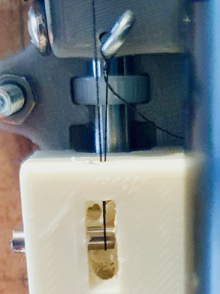
    The clamp screws ran into single-perimeter holes. That "worked" because pull-out strength can be ok. But it didn't really work for the idea in mind because the hole threads were vulnerable to torque-out and wear from frequently turning the loaded screw  ̶k̶n̶i̶v̶e̶s̶ threads (call it "slice-out"?). That required attention and a tool to torque up the screws carefully, and to carefully torque all of them instead of just half (one side) to ensure even (i.e. minimum) tension.

    Not the quick, casual, routine operation I had in mind.  


    Reducing that mess to two thumb nuts:

    • better reflects the "very inexpensive" idea of making it easy to drop in a daily-driver rotary tool
    • improves durability by turning metal nuts on metal screws to secure/release the clamp while the screws in plastic can be driven once and left alone.

    A less evident fault with the first printed Z axis was sagging PLA around the warm motor.

    left=up; right=down

    The motor mount screw holes yielded some but didn't fully fail. I don't know if that's because it stopped creeping after I turned down the motor current, if it relaxed to some equilibrium and stopped there, or if it was ten minutes from falling apart.

    In any case, it wasn't a big surprise that the PLA softened.

    For the first version I opted to just print it and see what happened before getting too wrapped up in trying to anticipate heat effects. It didn't take long to confirm that the pulley(s) couldn't be PLA. PETG is working fine there (white vs. blue in the second pic). The motor attachment to the base part wasn't so obviously bad. It looked fine for a while. Distortion around the screws became evident after a while but wasn't a big deal. The screws continued to hold. It was "ok" to use but definitely needed some help.

    I suppose it's possible that with two motors the motor current could be reduced enough to keep the motors cool enough for PLA. I haven't tested that. (A second motor/pulley/cord can be installed for cheap insurance against dropping the big angry part. That's more of a concern in the laser-cut version where the cord/s is/are hidden and run close by sharp edges.)


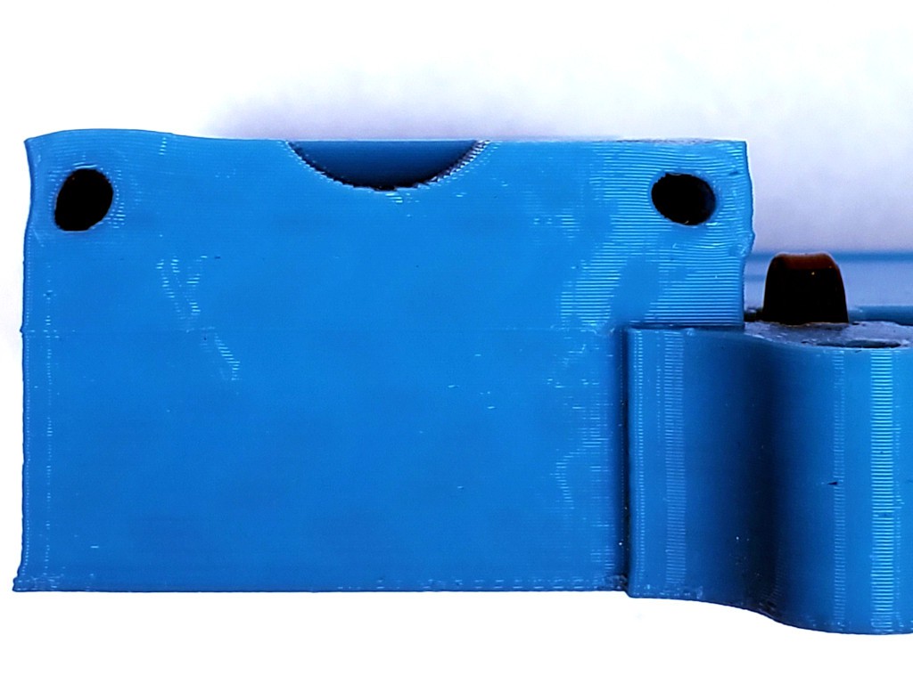
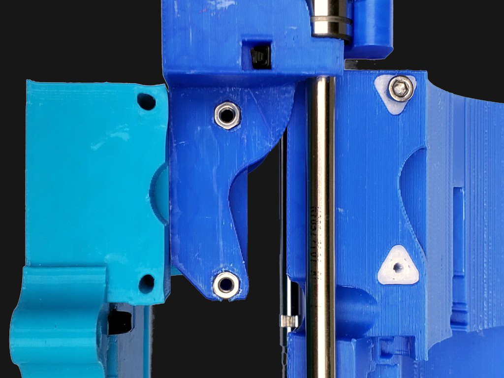
    In the second version I tried embedding hex nuts at the surface -- middle in the pic below. They didn't help pull-out strength which still relied on the screws holding in the plastic part and I doubt they got any less hot than before. The idea was to try spreading the radial load over a larger area of PLA. I think they actually helped more than what I had in mind: by fixing the screws perpendicular to the motor tabs they spread the radial loads much more by requiring the motor to drag the whole screws sideways through the PLA if it was going to go anywhere. They also protected the threads in the PLA hole from stripping by providing a hard stop to torque the screws into. It looks like they worked because there's no indication that they moved. Caveat I didn't run that version very long or in hot weather.

    While the nuts seem to have worked well as far as tested, that arrangement had a couple of drawbacks. If a nut were removed, I didn't have any great ideas for how to put it back in the right orientation to match the nut thread to the hole thread. And nuts would add a line to the BoM which I'm trying to keep short. 

    For this version I'm trying PETG plugs in the PLA part to hold the hot motor mount screws -- right side in the pic above. PETG (or whatever...

    Read more »

  • Meh. New Z is fail.

    Paul McClay05/03/2024 at 22:26 3 comments

    Pretty but not stiff. Time to learn me some FEA? Back to the drawing board.

    Thumb nuts > bunch of screws.

  • Thicker Brass bis: Made a Thing

    Paul McClay02/20/2024 at 05:59 0 comments

    (2 Jul 2024 update: add 2nd pic)

    Made a thing from brass thicker than paper and that isn't just a flat cutout:

    a milestone that I didn't imagine when I started messing with this toy-scale CNC stuff
    <update>
    Tried again
    • better paint (more correct color and less wrinkly) but still not right
    • better milling
    </update>

    It's a shanyrak[1], as stylized in the national emblem of Kazakhstan[2][3]. Because my wife is Kazakh.

    Yes, the paint wrinkled when I sprayed clear over it. A lesson in alkyd/acrylic/time issues. Call it a rough draft/proof-of-concept piece. Or maybe I should brag up my successfully executed wrinkle finish.

    In October last year (writing in Feb '24), in a press to maybe possibly get a competitive HaD Prize final entry together (failed but that's a different story), I tried cutting something more interesting than a backlash test pattern in a chunk of brass thicker than a thin sheet, which failed in a confidence-inspiring way.

    Months of other stuff happened.

    When opportunity to try again came around, I had the idea of (re)starting with a simple figure that my wife might like -- a shanyrak -- since she tolerates all this nonsense. And Valentine's day was imminent.

    That was supposed to be simple but turned into another scope creep fest... ...which could turn this into a dissertation that never gets finished so maybe I'll just add some notes to the [2] footnote in case I ever come back to write more about that.


    Process

    roughing + lowest flats

    I rough cut the face, outline, and the center pocket down to a level above any detail with a 1mm end mill. Then cut the deepest pockets to final shape & depth with a 0.38 mm (0.015 in) mill.

    mostly rough but finished the deepest areas

    I guess it doesn't take much metal to make a (relatively) big pile of glitter. 

    beware the glitter bomb if not caged

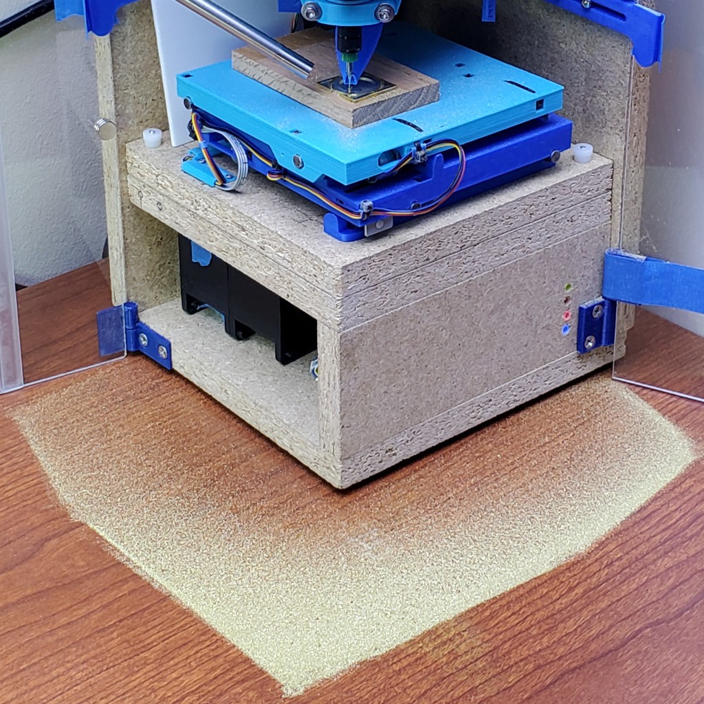
    Here's an opportunistic illustration of the divided project architecture: 1) the CNC core, whether this project here or elder sibling #Minamil 2dc: a minimal CNC mill, and 2) a structure that can be something fancy like parallel work in progress at #"Desk Accessory" CNC Milling Machine but doesn't have to be.

    The CNC part doesn't care whether it's in a tidy little box or scattering chips to the winds. If you're here for the CNC you can build the CNC and carry on.

    This pic shows a concrete illustration of the realized practicality of having a "desktop" CNC on my desk. The mess stayed in the box and that little patch is trivial to suck up with a hand vac. So long as it's sitting on a flat surface, which I think is a reasonable expectation for a desk.

    (having written "vac" I probably should add "HEPA". and the opening in the box under the XY table is for an air filter that isn't there yet -- the double-stack fan (high static pressure) will pull air down and (filtered) out the back so fine dust doesn't float up out the open top of the enclosure. which it does. that arrangement worked pretty well in the previous frame build. that all could be replaced with a vacuum hose stuck in a hole in the same spot -- which could be interchangeable if the fan and vac hose were the same diameter. i'll have to write all this air/dust stuff in a log at some point and trade all these words for a link to that. after finishing the fan/filter box there.)


    paint - and lost messages from the future

    Paint's not my thing. What I learned from this encounter is to do pretty much everything differently.

    I think I cleaned the surface adequately. It was freshly cut and cut dry so it should have been pretty clean after vacuuming out chiplets anyhow. 

    I used a rattle can, which meant masking around the workpiece and covering a fairly large area to manage overspray.

    Lesson: dust again after masking & draping.

    This was weird: That's probably too much paint for a first/single coat. I ended up spraying a load of paint...

    Read more »

  • Build? Start here.

    Paul McClay02/06/2024 at 05:39 0 comments

    (15 Oct 2024 update: Discord getting traction; less old "less simple" frame image)


    the this bone's connected to the that bone

    I've tried to make the CNC part of this (relatively) easy to reproduce from some 3d printed parts and a minimum of other stuff. It should go together by assembly with as near to zero fabrication as possible.

    Writing up how to actually get that done is a project in itself. What I have so far is pretty rough, but I think it conveys enough information to give you a fighting chance to build a working machine.  As of writing, I intend for this log entry to serve as a stable "start here" point with links to the latest work in progress as it evolves.

    Please let me know If you're thinking about actually building one of these. I've set up a Discord server. which has gained some traction as the place to plug in if you want to build one of these for yourself for real. (I've also enabled "public chat" for this project (big orange button on the project page, or right here) and you're welcome to check in there if it suits you better, but, as of mid-October 2024, you'll find it pretty quiet in there.)


    Here's what I've got so far...

    Read more »

  • Jolly Wrencher 2023

    Paul McClay01/01/2024 at 05:57 0 comments


    Cut but didn't publish this back in October, so I better hustle it up here before 2023 expires (in my timezone)...

    Read more »

  • Thicker Brass

    Paul McClay10/10/2023 at 00:26 0 comments


    Brass. More than 5 mil thick.

    If you squint, you might see a Jolly Wrencher in there. It didn't come out like I wanted, but the fault was mine.

    Read more »

View all 24 project logs

Enjoy this project?

Share

Discussions

Gravis wrote 03/08/2024 at 12:06 point

I like this project and have a recommendation: change the stage so that each axis travels from -50% to +50% (of it's width) from it's original position. Exceeding 50% increase the chances of tramming issues.

  Are you sure? yes | no

Paul McClay wrote 03/08/2024 at 21:07 point

Thanks Gravis for your interest, comment, and recommendation.

Maybe I don't understand what you mean. My first impression is that the mechanical change you suggest would lead to a more conventional layout and a larger footprint. For this project I'd rather keep the small footprint than chase better tram.  With tiny endmills the unadjusted tram hasn't caused enough trouble yet to prompt any effort to make it better, so I don't yet know what I'll end up with if I (anyone) ever get around to trying to tram this thing as it is.

Do you mean that defining "home" at mid-travel and tramming there can minimize variation between there and either end vs tramming at one end? 

For best stiffness, this layout favors operation near the "home" ends of the X & Y axes. Happily, it suffers much less loss of stiffness at full extension than I expected. In case it's not already clear (in the description/pix as of writing this comment), the first part of this page shows how these X & Y axes work: https://hackaday.io/project/174370-minamil-2dc-a-minimal-cnc-mill/log/185281-some-of-the-basic-ideas-that-seem-to-be-working

  Are you sure? yes | no

Gravis wrote 03/11/2024 at 01:08 point

Yes, I do mean that "home" position would be at 50% of the stroke distance of the actuator.

Despite being stiff, it will invariably sag more and more the further it is from the home position. If you place the home position at exactly 50% of the actuator stroke distance then that will minimize the sagging on each axis.

Sagging compounds with each axis, so cutting something on the outermost limit of both axes will be the worst case scenario.

  Are you sure? yes | no

Paul McClay wrote 03/19/2024 at 04:06 point
I think you're describing a different mechanism that would have different trade-offs. In other words, a mechanism that isn't different from what's already common.

  Are you sure? yes | no

Similar Projects

Does this project spark your interest?

Become a member to follow this project and never miss any updates