J.C. Nelson
-
Marlin! (Round 2)
12/30/2018 at 01:02 • 0 commentsFirst off, some clarifications from discoveries since the last log:
1. The USB B /CH340 and ESP8266 share the same USART, Serial1. This is why plugging in USB kills the ESP - they didn't want conflicts.
2. I've had no success getting USB working through the female connector, despite having a spare A->A cable. The serial that works is the output of the CH340, and it should be zero surprise it works since it's basically a dedicated FTDI clone.
Secondly...never accidentally leave test code in.
I removed a "blink forever" line from Marlin's main, re-enabled watchdog, and boom, I can issue commands to Marlin. After a few more adjustments it will be time to plug it into the printer.
Did I mention you can do WIFI printing? Yeah. You connect to Marlin by telnetting to Port 23 on the ESP and using the Serial bridge. Soon Windows, Com0Com will give you a virtual com port for Marlin. Or ESP3D could be run.
What does not work:
SD. Marlin uses SPI. This board uses SDIO. I need to test if SDIO via Arduino libraries works.
LCD. Nope, not even a little bit, yet. I'll need to figure out FSMC initialization before it will work.
All changes are pushed to my github, so you can enjoy if broken builds of Marlin are your thing.
start echo: External Reset Marlin bugfix-2.0.x echo: Last Updated: 2018-01-20 | Author: (xC0000005, Lerdge-X Config) echo:Compiled: Dec 29 2018 echo: Free Memory: 51035 PlannerBufferBytes: 1344 echo:Hardcoded Default Settings Loaded echo: G21 ; Units in mm (mm) echo:Filament settings: Disabled echo: M200 D3.00 echo: M200 D0 echo:Steps per unit: echo: M92 X80.00 Y80.00 Z4000.00 E500.00 echo:Maximum feedrates (units/s): echo: M203 X300.00 Y300.00 Z5.00 E25.00 echo:Maximum Acceleration (units/s2): echo: M201 X3000.00 Y3000.00 Z100.00 E10000.00 echo:Acceleration (units/s2): P<print_accel> R<retract_accel> T<travel_accel> echo: M204 P3000.00 R3000.00 T3000.00 echo:Advanced: B<min_segment_time_us> S<min_feedrate> T<min_travel_feedrate> X<max_x_jerk> Y<max_y_jerk> Z<max_z_jerk> E<max_e_jerk> echo: M205 B20000.00 S0.00 T0.00 X10.00 Y10.00 Z0.30 E5.00 echo:Home offset: echo: M206 X0.00 Y0.00 Z0.00 echo:PID settings: echo: M301 P22.20 I1.08 D114.00 echo:SD init fail G1 X ok M503 echo: G21 ; Units in mm (mm) echo:Filament settings: Disabled echo: M200 D3.00 echo: M200 D0 echo:Steps per unit: echo: M92 X80.00 Y80.00 Z4000.00 E500.00 -
USB!
12/29/2018 at 06:35 • 2 commentsAfter my last post, I went back and studied how code that actually can initialize the board correctly worked. With a little borrowed code from micropython sample, I was able to initialze the board successfully, and communicate outbound at much faster rates. Inbound data works in a test sketch, but not in Marlin yet. Now I can use USB instead of having to wire up to the serial1 via a FTDI clone.
Now I have an ESP8266 hooked to Serial1 and output via USB, so in general, this is very good.
Notes on the ESP module - For some reason, if I plug into USB, it cuts power to the ESP8266 module. These two do not share the same pins, so there's no logical reason I can find for this. Marlin supports two serial ports in 2.x, so it would be nice to enable both. Perhaps there's a cutoff circuit on the expansion module that can be disabled - I'm not sure yet.
I'm just happy to be able to send and receive data via USB.
-
Lerdge Clock Issues Identified
12/29/2018 at 01:55 • 2 commentsI noted in the previous log that the failure to run at faster baud was probably clock related. Today I built a binary that dumps the oscillator and clock configs to see how the bootloader and reboot works, and here's what I found - "Letting the bootloader configure the clock" is bad.
Here's the clock config from both:OscillatorConfig: OscillatorType:15 (all of them) HSEState:0 LSEState:0 HSIState:1 HSICalibrationValue:16 LSIState:0 PLLConfig: PLL.PLLState:1 PLL.PLLSource:0 PLL.PLLM:16 PLL.PLLN:192 PLL.PLLP:2 PLL.PLLQ:4 Obtaining Clock Config: Obtained Clock Config ClockType:15 SYSCLKSource:0 AHBCLKDivider:0 APB1CLKDivider:0 APB2CLKDivider:0 Flash Latency:5So, that's what is wrong. If I attempt to initialize the oscillators, the board hangs, so I need to debug to this and figure it out.
-
Connecting an ESP8266-01 to a Lerdge Board
12/28/2018 at 19:24 • 3 commentsIf you own the lerdge USB/Wifi printing module, you've probably looked at that 8 pin header and thought "It would be nice to do serial printing." And it probably would. However, in the lerdge store's description, they basically say other ESP8266-01 modules don't work.
It's sort of a lie, sort of not. Lerdge does not release their firmware (though anyone with a module could dump it), and they don't document how the connection works. But that doesn't mean much to me, so I ordered a $2 ESP8266-01 from China, and when it arrived, I flashed ESP-LINk on it and plugged it into the lerdge. After adjusting for my hideously slow baud rate (again, probably a clock problem)
I got the following output:
![]()
So...can we enable standard Wifi Serial printing? Yes.
Is it easy/Working? Not yet. But it's not far off.
There's no custom code other than my marlin build at work here, so it's almost certain we can use the ESP8266 wifi printing code directly on the board once we get it running. I'll be checking the oscillator config soon to see why we're having problems, and I'm hoping that's directly related to why USB and SDIO don't work yet.
-
Marlin...sort of.
12/24/2018 at 02:08 • 1 comment![]()
Today, while taking a break, I sat down and studied why it was that something like simple serial communication didn't work. I could bit-bang serial, sure, but the USARTs are present and hooked up for a reason.
I began studying how the firmware initialized the USART (which it does while upgrading the bootloader) and noticed that much of the time, the USB_OTG init was used.
Which would not leave those pins free for Serial.
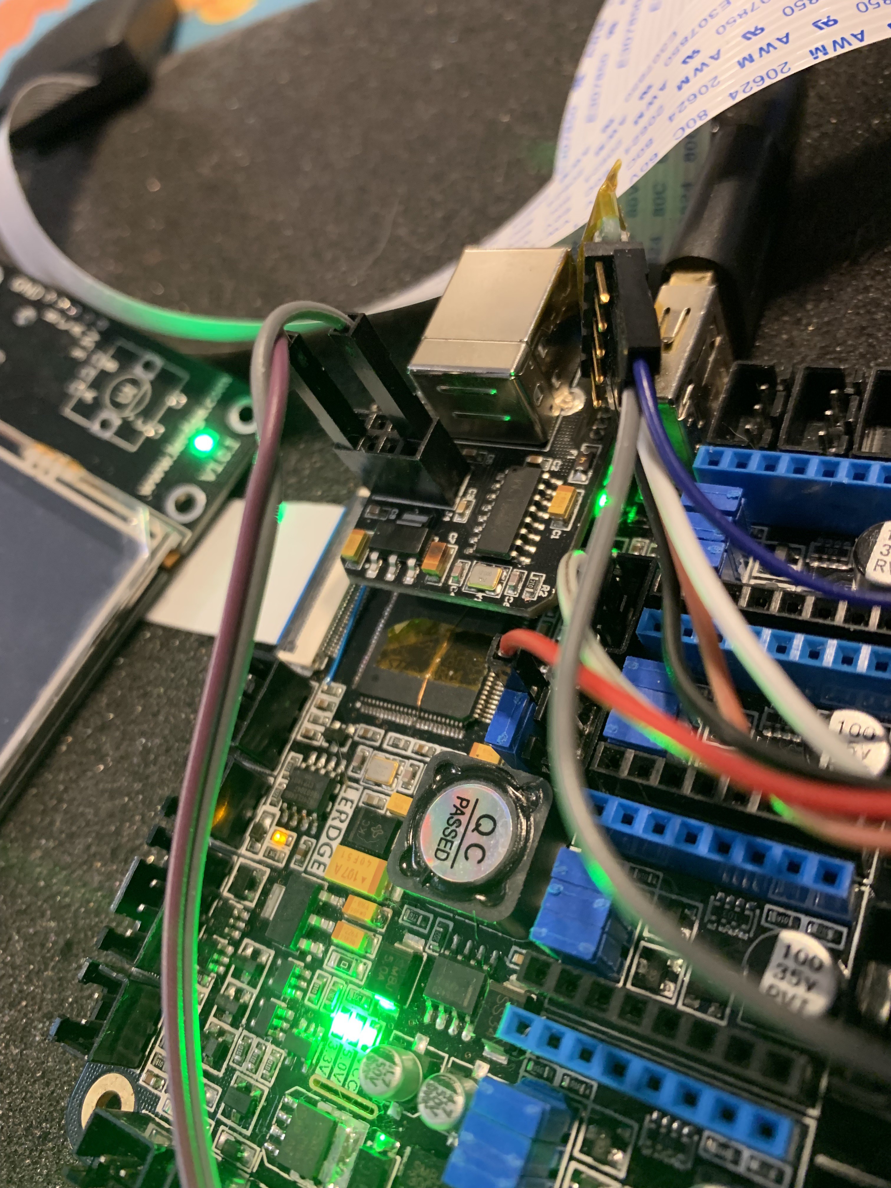
So I made a few changes to the pins map and tried again, and this time, got a beautiful spew, so long as I keep the baud rate slow. That may be a side effect of my FTDI clone, or maybe it's some initialization issue with the serial port, but the very next thing I did was set Marlin's serial port to 1, baud rate to 9600, and compiled. After booting it attached to the adapter...
--- Miniterm on /dev/cu.usbserial-A4012RZG  9600,8,N,1 ---
--- Quit: Ctrl+C | Menu: Ctrl+T | Help: Ctrl+T followed by Ctrl+H ---
start
echo: External Reset
Marlin bugfix-2.0.x

echo: Last Updated: 2018-01-20 | Author: (xC0000005, Lerdge-X Config)
echo:Compiled: Dec 23 2018
echo: Free Memory: 51139  PlannerBufferBytes: 1344
echo:Hardcoded Default Settings Loaded
echo:  G21    ; Units in mm (mm)

echo:Filament settings: Disabled
echo:  M200 D3.00
echo:  M200 D0
echo:Steps per unit:
echo:  M92 X80.00 Y80.00 Z4000.00 E500.00
echo:Maximum feedrates (units/s):
echo:  M203 X300.00 Y300.00 Z5.00 E25.00
echo:Maximum Acceleration (units/s2):
echo:  M201 X3000.00 Y3000.00 Z100.00 E10000.00
echo:Acceleration (units/s2): P<print_accel> R<retract_accel> T<travel_accel>
echo:  M204 P3000.00 R3000.00 T3000.00
echo:Advanced: B<min_segment_time_us> S<min_feedrate> T<min_travel_feedrate> X<max_x_jerk> Y<max_y_jerk> Z<max_z_jerk> E<max_e_jerk>
echo:  M205 B20000.00 S0.00 T0.00 X10.00 Y10.00 Z0.30 E5.00
echo:Home offset:
echo:  M206 X0.00 Y0.00 Z0.00
echo:PID settings:
echo:  M301 P22.20 I1.08 D114.00
echo:SD init fail
This is a thing of beauty. It's sitting on my table, blinking. It doesn't receive anything. I know or a fact the purple pin (lower left, if you're holding it so the USB adapter is facing upwards) is the TX. Nothing else works. Connecting to the right pin (the upper right, which is where a normal ESP2866 module would have RX) doesn't let me send anything. There's something missing - I'm just not sure what, yet.
-
Unbricking a Lerdge-X board (the sequel)
12/21/2018 at 19:58 • 7 commentsAs I noted, I had overwritten my bootloader with non functional code. Having uploaded and let everyone else test the loader, it was time for me to do it, too. To do this, I needed to put the board into serial loader mode so the ST-Link would have time to get ahold of the chip.
To do that, I pulled Boot0 high (connected it to the +3.3v from the ST-Link, which I'm using to power the board), and Boot1 Low (connected it to the middle pin on a sensor port.
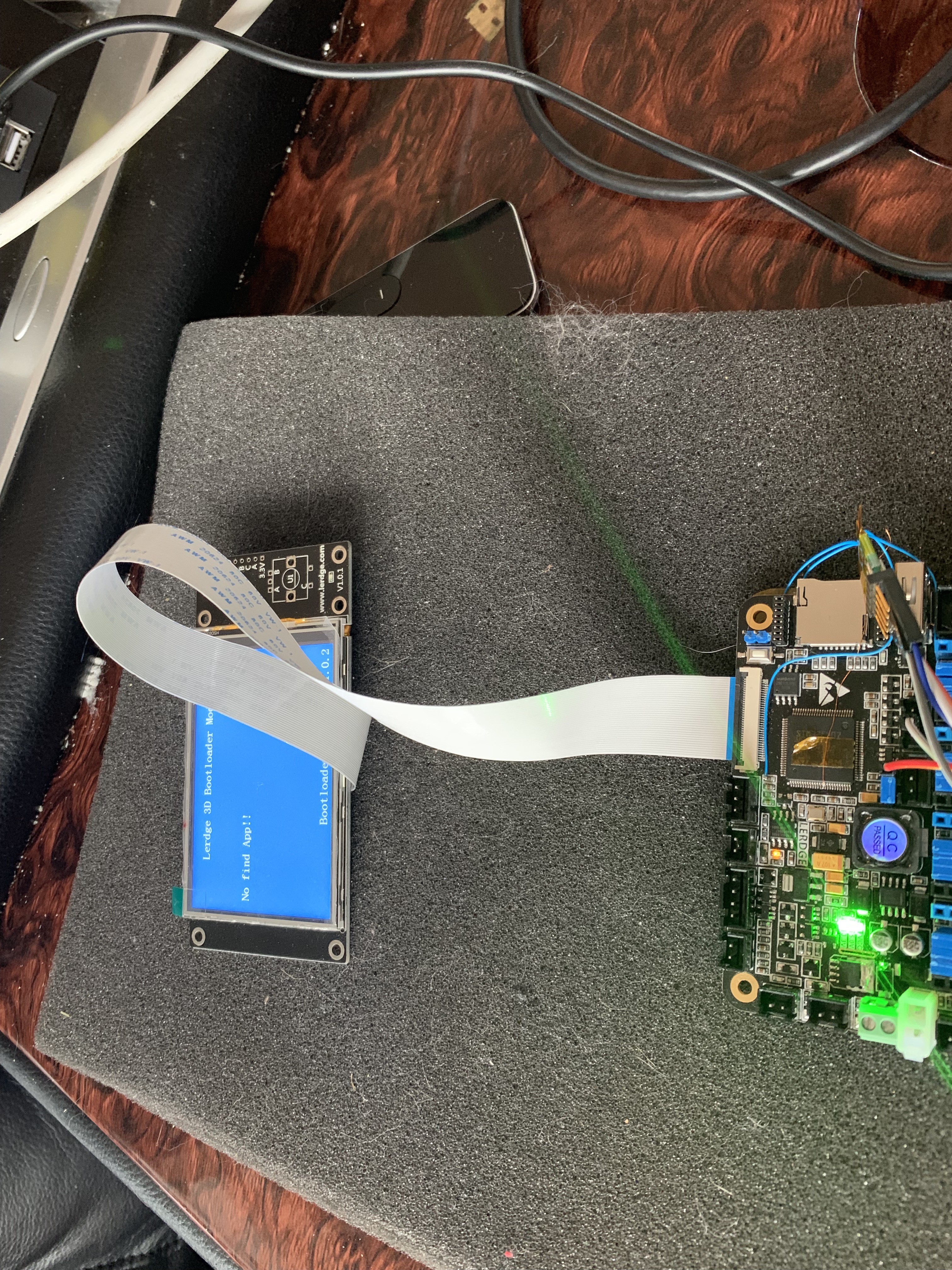
I was immediately able to reset the chip, flash the lerdge base bootloader on, and get my beautiful "NO APP" Error message.
This is 100% expected - after a reflash, there's no app on the board. If you wanted to move back to Lerdge's firmware, you'd proceed with a normal force update mode.
![]()
-
Bricking a Lerdge-X and other fun things to do
12/21/2018 at 18:08 • 0 commentsSo to recap, I've been able to run code that blinks LEDs and reads/writes on both the Lerdge K and Lerdge X boards, but every attempt to use Serial or USB results in no fault, but no output, either, and I kept coming back to the fact that other code runs fine, but other code doesn't run after lerdge's bootloader.
It was time to put up or shut up and reset the board, test my recovered bootloader, and then get into the internals of the board to understand why anything short of bit-banging serial doesn't work.To do this, I first had to unlock the board, mostly using the steps here:
Do not panic if the write takes a while - the chip is erasing itself.
Once this was done, I could then flash on code using st-flash, which is very handy.
The problem? Remember my previous log, where I noted that if you hard hang the chip with no clock config, you can't use SWD? Yeah, that. I uploaded a sketch still using the variant code which allows the bootloader to init the clock.
My X board no longer responds to SWD.
All is not lost. I have wires soldered to both BOOT0 and BOOT1, so I can recover by pulling the right ones to ground. That will hold the chip for me to load better code on.
But, family is coming into town. My time on this project will be limited until after the holidays. In the mean time, I may poke at the -K board using only the lerdge bootloader method, but don't expect a ton of updates.
-
Hooking an ST-Link to The Lerdge X and K - An Illustration
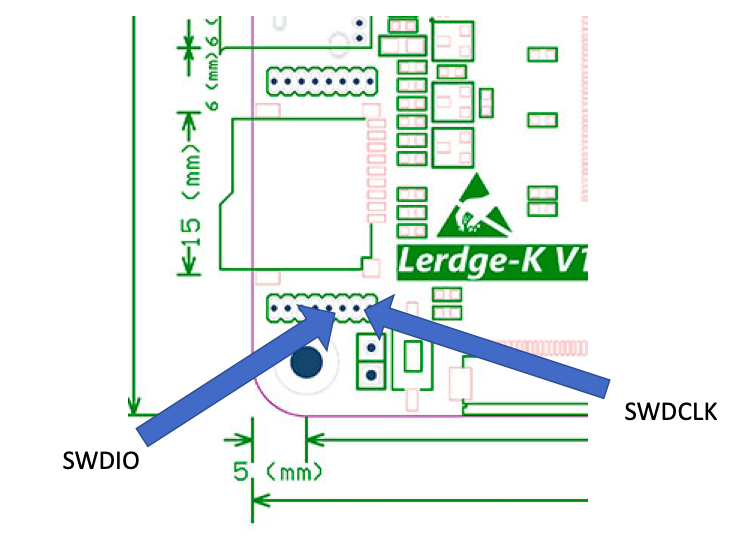
12/19/2018 at 22:38 • 5 commentsI've been asked how you hook an STLink to the lerdge X and K. I have zero idea about the S because I don't own one, but here's a illustration (I checked twice and I think I go the CLK/IO lines right - I usually hook them up, and if I can't probe the chip, reverse them. To describe it verbally, it's the pair of pins one from the right on the bottom row. I hook power to the VCC jumper, GND to the middle pin on any of the servo headers.
![]()
-
Lerdge-K bootloader dumped
12/19/2018 at 19:50 • 0 commentsI've added the K bootloader to the files section (and for fun, I dumped past it and found my arduino sketch right where I expected). This will let you restore a K board you've accidentally (or intentionally) wiped the loader on. I was only able to do this because someone sent me a K board (not naming them because I'm not sure if they want to be named). If you'd like to do the same on an S, I'll upload the sketch binary. You let it run, attach, then dump ram. You'll need to work out the ST-Link header pins - I don't know those for the S.
Edit to add - yes, this means I've run my own code on the K now.
![]()
-
Bootloader Confirmations
12/16/2018 at 15:23 • 0 commentsThis log is basically to confirm that two different people have told me the base bootloader works - one on a -S, one on a -X. I'm not recommending you erase your mainboard, but if you do, and you want to go back to the Lerdge firmware, you can. Happy hacking, folks. Next up will likely be USB support.
Lerdge 3d Printer Mainboard Hacking
Breaking the encryption on the Lerdge series mainboards so I can try porting Marlin 2.0 to it.