 gertux
Before you can reprogram the ST-Link clone it has to be 'unlocked'. The only way to unlock it that I know of is by using OpenOCD.
You'll also need a second ST-Link clone or an other SWD programmer and some jumper wires.
The ST-Link clones have programming connections on the PCB. You can access them by sliding the cover of, the cover is not glued close but you can feel some friction.
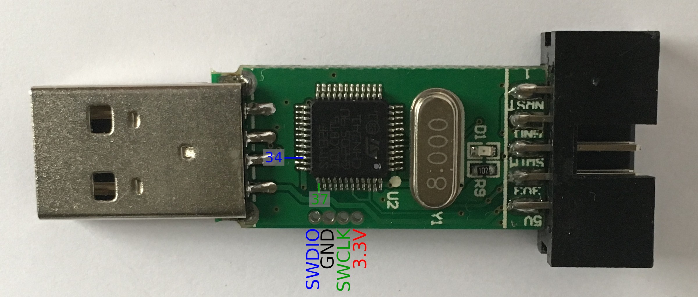
The PCB should look like the annotated picture, there are ST-Link clones where the pinouts are different but it's quite easy to measure your clone's pinout with a multimeter in continuity testing mode. The SWDIO connection should be connected to pin 34 (the pin numbers start with pin 1 at the location of the dot on the MCU) and SWCLK is pin 37.
Ground (GND) can be tested using the GND pin on the 10 pin header, the same goes for the 3.3V pin. It is not necessary to find the GND and 3.3V pins to program the clone because you can use the connections on the pin header, it is a good idea to measure it anyway to make sure you're right about the SWDIO and SWCLK connections.
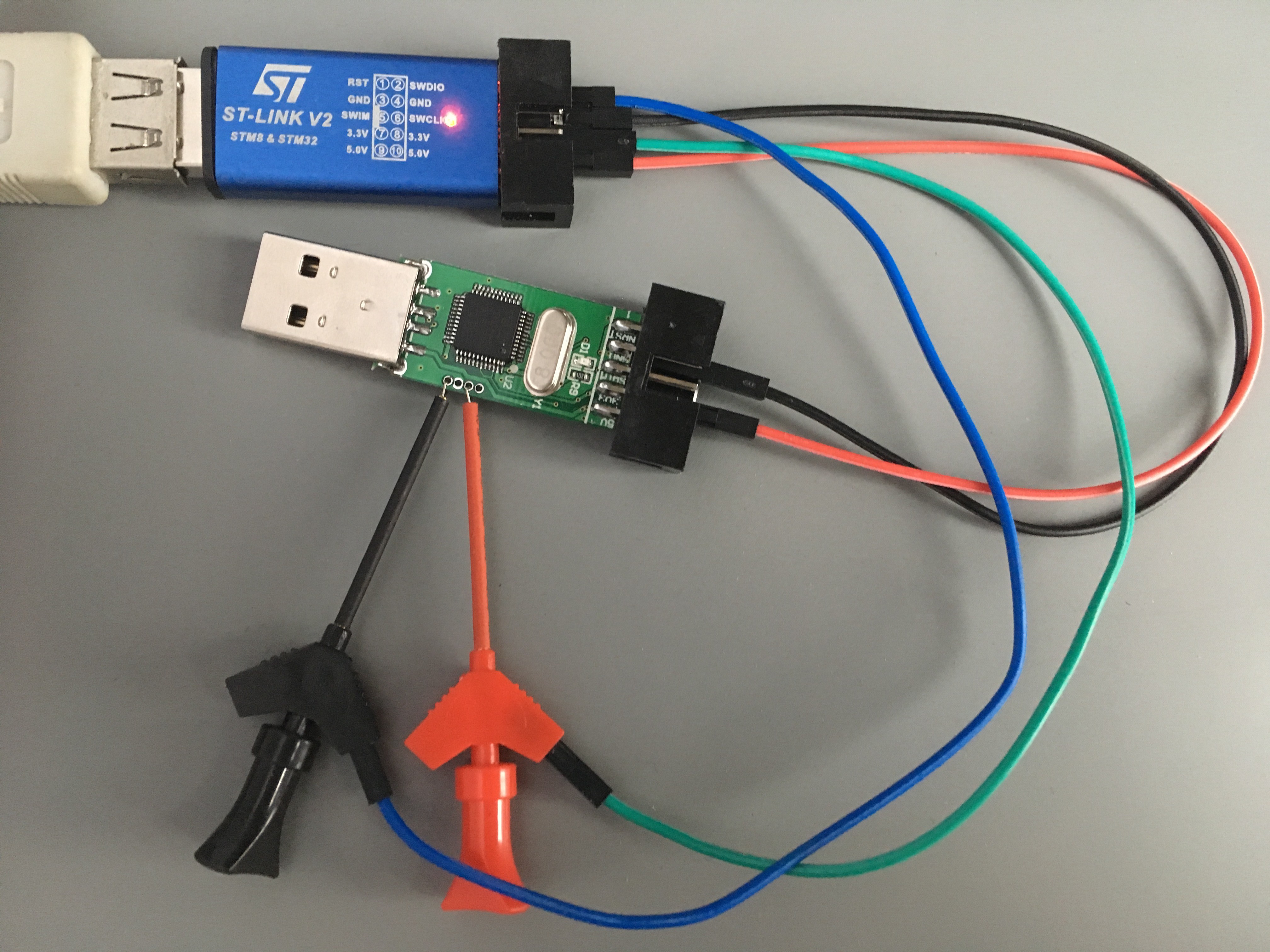
If you connect ground and 3.3V using the 10 pin header you should be able to use mini grabbers for the SWDIO an SWCLK signals.
Unlocking
$ openocd -f interface/stlink-v2.cfg -f target/stm32f1x.cfg -c "init" -c "halt" \
    -c "stm32f1x unlock 0" -c "shutdown"
Open On-Chip Debugger 0.10.0
Licensed under GNU GPL v2
For bug reports, read
        http://openocd.org/doc/doxygen/bugs.html
Info : auto-selecting first available session transport "hla_swd". To override use 'transport select '.
Info : The selected transport took over low-level target control. The results might differ compared to plain JTAG/SWD
adapter speed: 1000 kHz
adapter_nsrst_delay: 100
none separate
Info : Unable to match requested speed 1000 kHz, using 950 kHz
Info : Unable to match requested speed 1000 kHz, using 950 kHz
Info : clock speed 950 kHz
Info : STLINK v2 JTAG v28 API v2 SWIM v7 VID 0x0483 PID 0x3748
Info : using stlink api v2
Info : Target voltage: 3.249867
Info : stm32f1x.cpu: hardware has 6 breakpoints, 4 watchpoints
target halted due to debug-request, current mode: Thread
xPSR: 0x61000000 pc: 0x08003d5a msp: 0x20004e38
Info : device id = 0x20036410
Info : flash size = 128kbytes
stm32x unlocked.
INFO: a reset or power cycle is required for the new settings to take effect.
shutdown command invoked
Next power cycle the device by removing the 3.3V power wire.
You can now erase the flash and write your own firmware to it.
$ openocd -f interface/stlink-v2.cfg -f target/stm32f1x.cfg -c "init" -c "halt" \
    -c "flash write_image erase hello 0x8000000" -c "shutdown"
  Open On-Chip Debugger 0.10.0
  Licensed under GNU GPL v2
  For bug reports, read
          http://openocd.org/doc/doxygen/bugs.html
  Info : auto-selecting first available session transport "hla_swd". To override use 'transport select '.
  Info : The selected transport took over low-level target control. The results might differ compared to plain JTAG/SWD
  adapter speed: 1000 kHz
  adapter_nsrst_delay: 100
  none separate
  Info : Unable to match requested speed 1000 kHz, using 950 kHz
  Info : Unable to match requested speed 1000 kHz, using 950 kHz
  Info : clock speed 950 kHz
  Info : STLINK v2 JTAG v28 API v2 SWIM v7 VID 0x0483 PID 0x3748
  Info : using stlink api v2
  Info : Target voltage: 3.249867
  Info : stm32f1x.cpu: hardware has 6 breakpoints, 4 watchpoints
  auto erase enabled
  Info : device id = 0x20036410
  Info : flash size = 128kbytes
  target halted due to breakpoint, current mode: Thread
  xPSR: 0x61000000 pc: 0x2000003a msp: 0x20004e20
  wrote 21504 bytes from file hello in 1.222309s (17.181 KiB/s)
  shutdown command invoked
Discussions
Become a Hackaday.io Member
Create an account to leave a comment. Already have an account? Log In.
i did the same way
good idia
Are you sure? yes | no
Hi, what is the purpose of RP1? Is it to limit the current drained from the pins? If I were to use I2C pins, should I place the connection before RP1 right? In any case, it also seems a good component to desolder and access these pins directly.
Are you sure? yes | no
Thanks !
Are you sure? yes | no
It can be unlocked from the STLink Util.
1. Perform a Chip erase
2. Change the option byte. At this point a window will popup. Select "Disable" and hit "Apply"
3. "Disconnect" from target and then "Connect" again.
4. If you are not getting the connection screen with internal memory dump, you might have to repeat steps 2-3 one more time.
Detailed steps with pictures here: https://hw-by-design.blogspot.com/2018/08/gdb-debugwire.html
Are you sure? yes | no