 Bud Bennett
The latest schematic for this version is shown in the details section of this project.
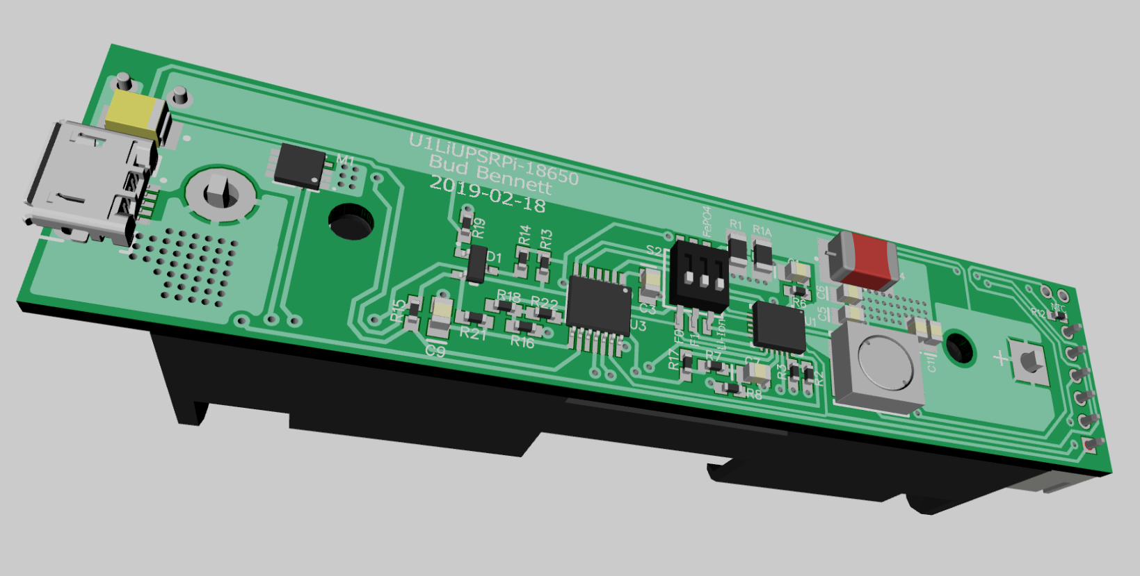
Now that the Hat version is pretty much performing to specifications, I'm ready to expand the UPS to an 18650 battery form factor. The only schematic differences between the two versions is the increased charging current to 1A and the removal of the LED indicators. Typical 18650 Li-Ion batteries have a capacity around 1.5-2.5Ah, so the UPS should charge the battery at about 1/2 C rate. More than this would overload a typical AC adapter rated for 2.5A @5V.
Almost all of the components are mounted on the top side of the PCB, which is the same width as the battery holder. The reset push button, 10K NTC thermistor, JST connector for the I2C interface, and the output voltage terminal block are also mounted on the bottom side of the PCB. I expect this unit to be mounted with the battery holder facing up, and servicing a headless Raspberry Pi in a closet somewhere, so the LED indicators were removed.
New PCBs for both versions were ordered from JLCPCB in 1 oz copper. I expect to receive them in a bit more than one week.
Discussions
Become a Hackaday.io Member
Create an account to leave a comment. Already have an account? Log In.