 2-Zons
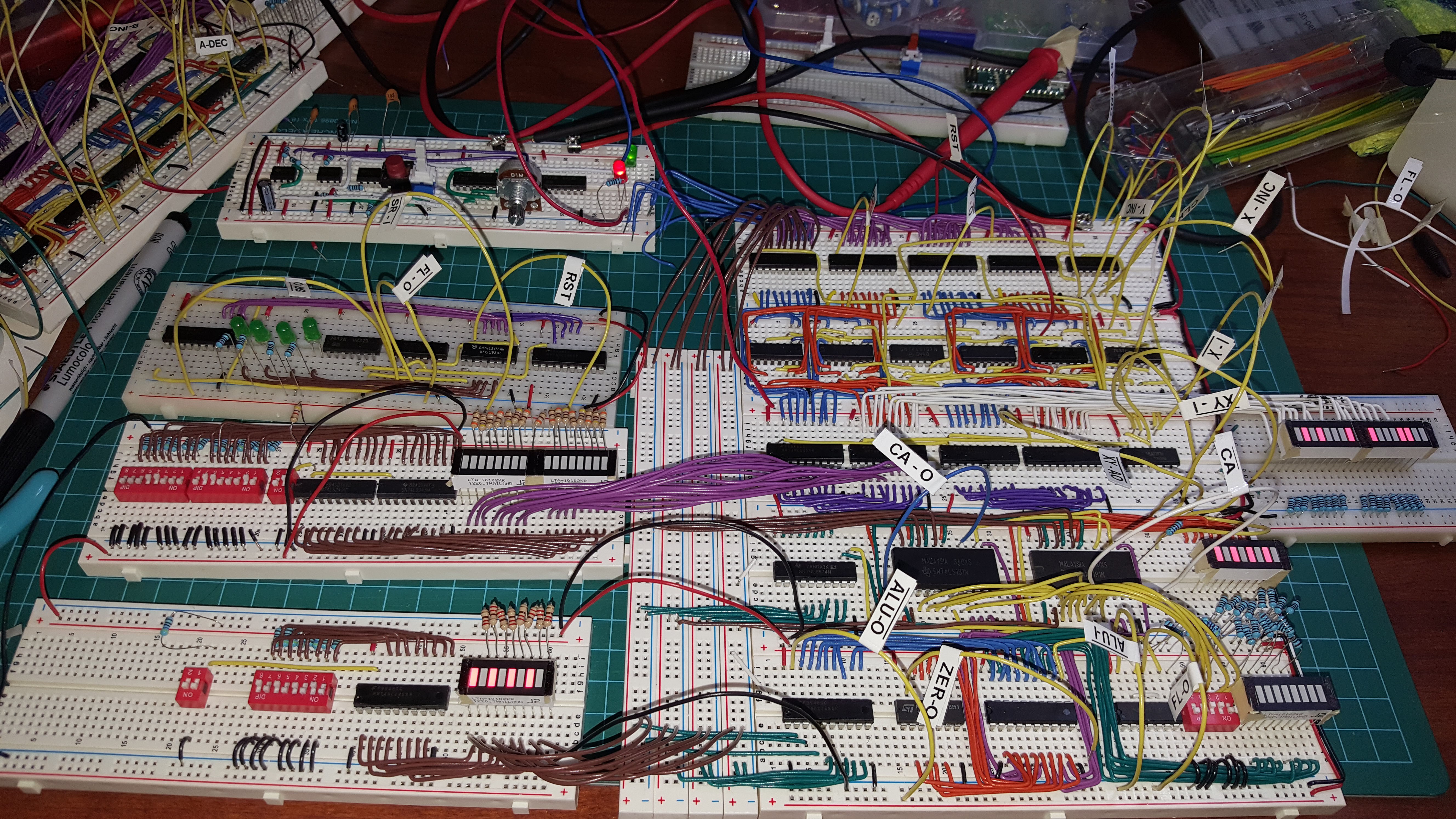
I've been working on combining the modules I have so far. It's been I little trickier than I'd hoped but It's coming along. I built a temporary data and address bus driver with LED readout. In my initial testing I just had the dip switches connected to the data inputs of the modules. This wouldn't let me test the modules output to the bus. So by separating the dip switches with their own bus driver I can now test what the modules put out on the data bus. I did the same with the address bus. I'w worried that all these dip switches are going to draw too much current though. I think if I make a front panel for the system I will use toggle switches that simply switch between VCC and GND.
On another note. Upverter sent me an email. They chose my project for a case study. They want to help me get it manufactured (PCB and components).
Discussions
Become a Hackaday.io Member
Create an account to leave a comment. Already have an account? Log In.
nice looking design!
Are you sure? yes | no
This looks very promising, Martin !
Are you sure? yes | no
Looking good! I am eager to fly back home in a few days so I can resume work on my computer. Keep up the good work!
Are you sure? yes | no