2-Zons
-
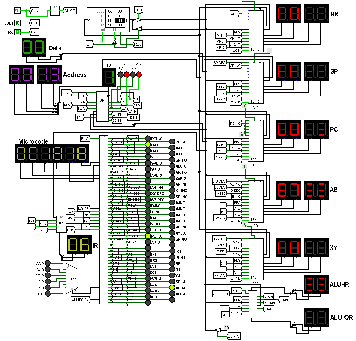
Debugged Logisim Design
01/01/2019 at 20:02 • 2 comments![]()
Added enough instructions to test out all the component designs. Found a bunch of bugs and fixed them. Learned a heck of a lot. Came up with some changes to the overall design, like having a control line to load the data-bus with zero's. This will save many cycles for certain instructions and allow for a CLR instruction. Before adding the zero control it took several cycles for an instruction to clear anything by XOR'ing it with itself in the ALU.
Another design change is the ability to transfer 16 bits in one cycle through the address bus, between registers. Currently it's only implemented with AR, being able to store what is on the address-bus. AR is an internal register not available to the programmer, used for holding addresses. Without it there would be no way for an instruction to load the PC from memory without changing the state of another register. In logisim all my 16 bit registers are copies of the same sub circuit so implementing 16 bit loads into other registers would be easy. I will need to do an analysis of my currently planned instruction set to see which registers could use it.
If anyone is interested in my files let me know and I'll upload them.
-
Logisim model working
12/29/2018 at 01:55 • 0 commentsI've don'e it. I've got my completed CPU design running in Logisim. Very handy tool indeed. I would be interested to know if the simulators in FPGA editors have some of the functionality of Logisim. Specifically, being able to edit and load RAM and ROM images.
I haven't programmed all the microcode into it yet, so haven't been able to ensure there are no design bugs. I have programmed a complete reset instruction that should work for hard and soft reset. It loads SP and PC from address $0000 and $0002. It doesn't clear any of the registers besides A, SP, SR and PC. The ZR flag is left set after it is finished. My plan for IRQ is that it will grab the IRQ vector from address $0004 after it pushes the SR and PC. It will be up the the IRQ routine to save SR, AB, or XY if required.
Now I just need to program a few more instruction in to fully test all areas of design. Still waiting for some more parts to start the actual build.
-
Building my Design in Logisim
12/26/2018 at 07:36 • 0 commentsWe'll I've been busy working out more details of my design in Logisim. I was finding it very helpful to think through my design by building the schematics in Upverter. I was working on the instruction decoder and was finding myself needing to figure out some logic. I was scribbling on paper to try and work it out when I thought I'd try and use Logisim. I had never used it before and didn't really want to learn another piece of software.
Wow, I'm sure glad I did. What a nice little program it is. I should have listened to @roelh 's advice to begin with. It's been really helpful in working out the details of the design. It doesn't have a library of standard IC's so I started my own library of the chips I'm using. I used the schematics from datasheets. I put in Schematics for for the 181 ALU and the 193 up/down counter that I'm using for my registers. Logisim does have an up/down counter in it's library but I built them from the schematics so I would hopefully simulate the same behavior.
I'm getting close to finishing the whole design. I still haven't received all of the components I need to start building on breadboard, but maybe it's not such a bad thing to be forced to do only planning before actually wiring anything.
I'll add a screen shot of the main circuit. If anyone's interested in the files let me know.
-
Status Register and Instruction Decoding Schematic
12/17/2018 at 22:10 • 2 commentsBuilt the schematic for the status register / instruction counter and instruction decoder with microcode (EEPROMs). This is more of a working design. Currently it has inverters on all the decoder outputs but many of the control signals are active low and will not require interting. When I build it I will optimize.
https://upverter.com/2-Zons/ec2b22eca1358d33/8-Bit-CPU-Status-Register-and-Instruction-Decoder/
I am building all the microcode in a database so I can run queries to try and find all the possible groups of control signals that are exclusionary (never used at the same time) this way I can use more encoders to reduce the amount of EEPROM's. Currently I need 5, but might be able to get it down to 3 or possibly 2. There are 50 control signals. If they were all exclusionary I could get by with 1 EEPROM (6 bits = 64 signals). After I've designed all the microcode I may even find there are control signals that aren't used in any instruction.
I've also been working on some slight redesigns of the other schematics, including the ALU. I found some LS181 and LS182's on ebay so I will be building my ALU out of those. Although I like @roelh's ALU design, I can reduce the chip count significantly by using 2 181's and a 182. I might just build @roelh's first as I won't be getting the 181's and 182 for a while.
I can't get to doing any actual building as I am still waiting on some key components to arrive, like wire and capacitors. Unfortunately there are no decent electronics shops where I live (near Edmonton, Alberta). There used to be an good one called Active Electronics but they shut down. There are a few small shops but they have exorbitant prices. I was going to get a roll of 22AWG hookup wire from them. They were charging $25 for a 50 foot roll. I've got several different 100 foot rolls on order for $8.50 USD each. I couldn't bring myself to pay that much for something that I've already ordered. I've spent more that I wanted to on this already. I'm just going to have to be patient and wait a bit until I can actually start building things.
-
Instructions ....
12/13/2018 at 00:10 • 1 commentOK, More massaging of the instruction set. I removed the inverse jumps (JNC, JNZ, JNM). You get the not jump condition in the next memory location after the jump. The only reason to have them IMHO is to make the code easier to read. I need the opcodes for more desirable instructions.
I re-added immediate indirect addressing for the MOV instruction so memory locations can work as pointers.
I found a bunch more instructions that were 16 bit and marked them.
I added a 16 bit memory to memory MOV. Need to think of a good way to indicate it for the assembler as both the 8 and 16 bit versions are using an address. Maybe MVL for move long, which could be used for all 16 bit moves.
After all these changes I have a few unused codes, which is a good place to be in.
I am realizing that this instruction set is going to be very iterative. I am sure I will be doing more and more tweaking as I get on with the design. As I am implementing the microcode in EEPROM's changes will be easy. I don't plan on working on an assembler until I have a very stable design. I do plan on using EEPROM's for regular programming as well, but I can program without an assembler.
https://docs.google.com/spreadsheets/d/1kbxYGDeIOszgvjPYRdes-bELOBlojT_tjxe_RD9MVUQ/edit?usp=sharing
-
I thought I was done with instructions for now
12/12/2018 at 05:17 • 3 commentsGoing over them one final time with advice from @roelh. I've updated them to show which are 16 bit and which are 8 bit. I've removed the XNR instruction, although I thought it was a good way to set a byte to FF, like the status register. Used the free'd up codes to add the opposite jump's JNC, JNZ, JNM, and some XY stack addressing to the ADD and SUB commands.
https://docs.google.com/spreadsheets/d/1kbxYGDeIOszgvjPYRdes-bELOBlojT_tjxe_RD9MVUQ/edit?usp=sharing
Going through this I'm questioning how I have the XY stack instructions currently. If it is being used as a stack that grows down in memory (starting at a high address and growing toward 0000h) then any time it is the destination it should be pre decremented. This way it will move to it's new address then store, then it will hold the address of the last byte it stored. When reading from the stack, or popping, it should post increment, so that it moves to the location where the next byte will be stored, and it will always be pointing to valid data (unless you hit bottom of the stack).
Is there something wrong with my thinking? If not then I have the increment and decrements of my XY stack instructions wrong.
Since I have a dedicated stack pointer (SP), should the XY stack grow towards FFFFh ? This way both stacks can share the same memory space. If so, using the above logic, store instructions to the XY stack should be pre incremented, and reads or pops from the stack should be post decremented. If so then my instructions are still wrong.
Is there anything I am missing?
-
Finished Instruction Set (For Now)
12/11/2018 at 12:46 • 2 commentsWhew, I am now at a point where I think I can move ahead. I have worked out a set of instructions (not set in stone) that I think will work. It's definitely not orthogonal. Without complicating the design by adding the ability to have 2 instruction registers or greatly simplifying the instruction set, I can't see a way of doing it.
The instruction syntax I am suing is "INStruction Source,Dest" e.g. MOV A,$D020
I think it has some very useful instructions. XY Can be used as another stack pointer. I didn't have to room to allow AB to be used as a pointer directly, so only XY can be used for register indirect instructions. One instruction it does not have is clear, so no direct way to clear the status register. You can XOR A with itself (should be 3 cycles) then MOV A,SR (2 cycles). Or if you can't use A, you can XOR a byte in RAM with itself or use a known zero location.
I have yet to receive enough parts to actually start building anything. I've ordered parts from several different vendors trying to get the best prices. With all the shipping charges though I'm not sure If I actually saved anything.
I have in instruction matrix on the google docs spreadsheet
https://docs.google.com/spreadsheets/d/1kbxYGDeIOszgvjPYRdes-bELOBlojT_tjxe_RD9MVUQ/edit?usp=sharing
-
More work on instructions
12/10/2018 at 09:20 • 4 commentsWith the help of some excellent feedback from @roelh I am reworking the instruction set. I have decided to move away from the load / store syntax and am moving to a 68K style move instruction to help avoid duplicating instructions. Each two operand instruction will be in the form of INSTR source,destination. I am building a database in Access to help me come up with my list of instruction. I've created a table of Operations :
MOV ADD SUB INC DEC PUS POP RES RTI RTS JMP JCA JZE JMI TST OR AND XOR XNR NOT JSR CMP
And a table of Operands:
A B X Y AB XY SP PC # ## . $ $## SR +SP -SP +XY +AB
(symbols are placeholders for Immediate, Absolute, Indirect and Immediate Indirect.)
The tables have info like the width of each operand, the number of operands for the operations. and notes. Just combining all these without using the same operand twice results in almost 8,000 instructions. I am working on using query's to help me build groups of instructions. This will help me prioritize modes for different registers. I want to give high functionality to the stack. I will be using AB as the data focused register and XY as the pointer focused one. I want to have the rules for the instructions be logical so you can easily remember which registers are capable of what. My first version of instructions had limitations on pointer style programming. With only 2 pointer registers (besides SP and PC) being able to do operations on memory will be important I think.
I will look at coming up with an easy way of auto publishing my Instruction info from the database somehow. I know office 365 have features similar to Google docs so It should be possible. Just haven't played around with it yet.
I'm already thinking that If this goes well (I build it in a reasonable amount of time). I might try taking a crack at a 16 bit CPU. I love the idea of having enough bits in the instruction code to have 3 bits for source register 3 bits for destination, 4 or 5 bits for operation etc. would be really cool. But I am getting way ahead of myself. Lets just get this one done. (reminding myself to watch the feature creep).
-
Fleshing out Instruction Set
12/09/2018 at 10:07 • 2 commentsI updated my instruction list using different addressing modes and the new ALU functions. I am over by 57 Instructions. Going to have to do some prioritizing. I can't beleive they didn't even use all 256 Instructions on the 6502 and others. I guess when they were drawing all the microcode manually on massive film, walking on it with their socks it kind of makes sense.
https://docs.google.com/spreadsheets/d/1kbxYGDeIOszgvjPYRdes-bELOBlojT_tjxe_RD9MVUQ/edit?usp=sharing
Added schematic for program counter
https://upverter.com/2-Zons/28ed54fb010b5ac1/Program-Counter-16-bit-Register-for-8-bit-TTL-CPU/
-
More Schematic Work
12/09/2018 at 01:16 • 1 commentCleaned up the 16 bit register schematic quite a bit. Getting better with the upverter software.
https://upverter.com/2-Zons/2bdc142f8f99588f/16-bit--Dual-8-Bit-register-with-Up--Down-/
Implemented the fast carry in the ALU for the flag and at bit 4. Didn't change the 4 bit D-type registers to 8 bit ones as I don't have those chips. I'm not going to order more chips till I flesh out the schematics. Keep shipping costs to a min. Hopefully I will only need one more order to get all the parts I need.
https://upverter.com/2-Zons/2f903c2bed9cef6d/8-bit-ALU-w-input-and-output-registers/
Started the master schematic the ties all the modules together.
https://upverter.com/2-Zons/1a1b5dbb645ac3ba/8-Bit-TTL-CPU-built-on-a-breadboard/
Put png exports of the schematics up in the gallery.
8 Bit Breadboard CPU
A home-brew 8 bit Microprocessor built on a breadboard 64K Address Space, IRQ, and DMA 16 Bit Stack Pointer, 4 8 bit Registers or 2 16 bit