David Troetschel
-
Testing Circuits
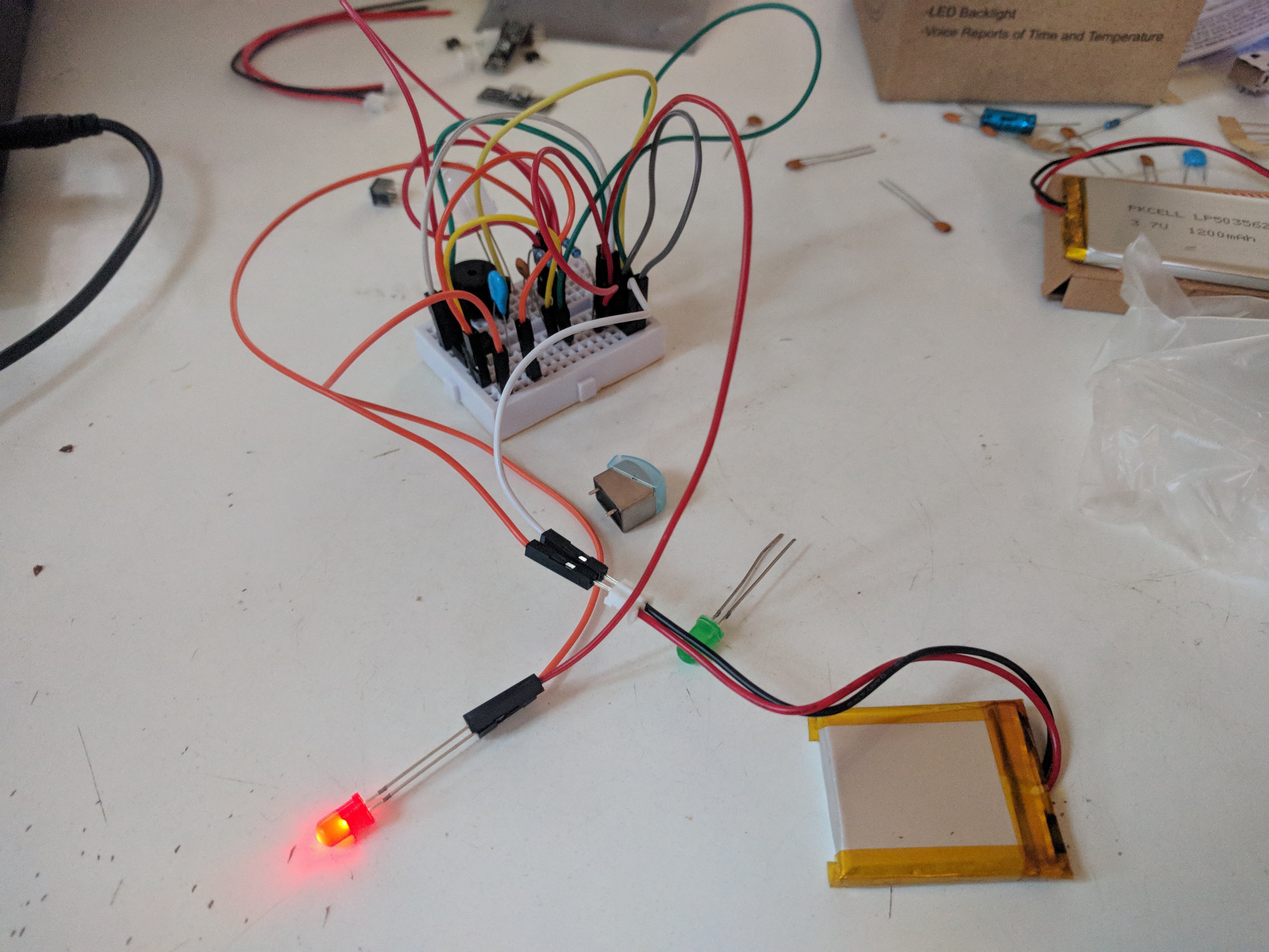
03/06/2019 at 14:24 • 0 comments![]() I've been testing some circuits with a little success.
I've been testing some circuits with a little success.I think I'll get this it'll just take some time.
Right now the LM386 seems like a good bet, anyone have much experience with it?
-
Read heads and circuits
02/26/2019 at 18:56 • 0 comments![]()
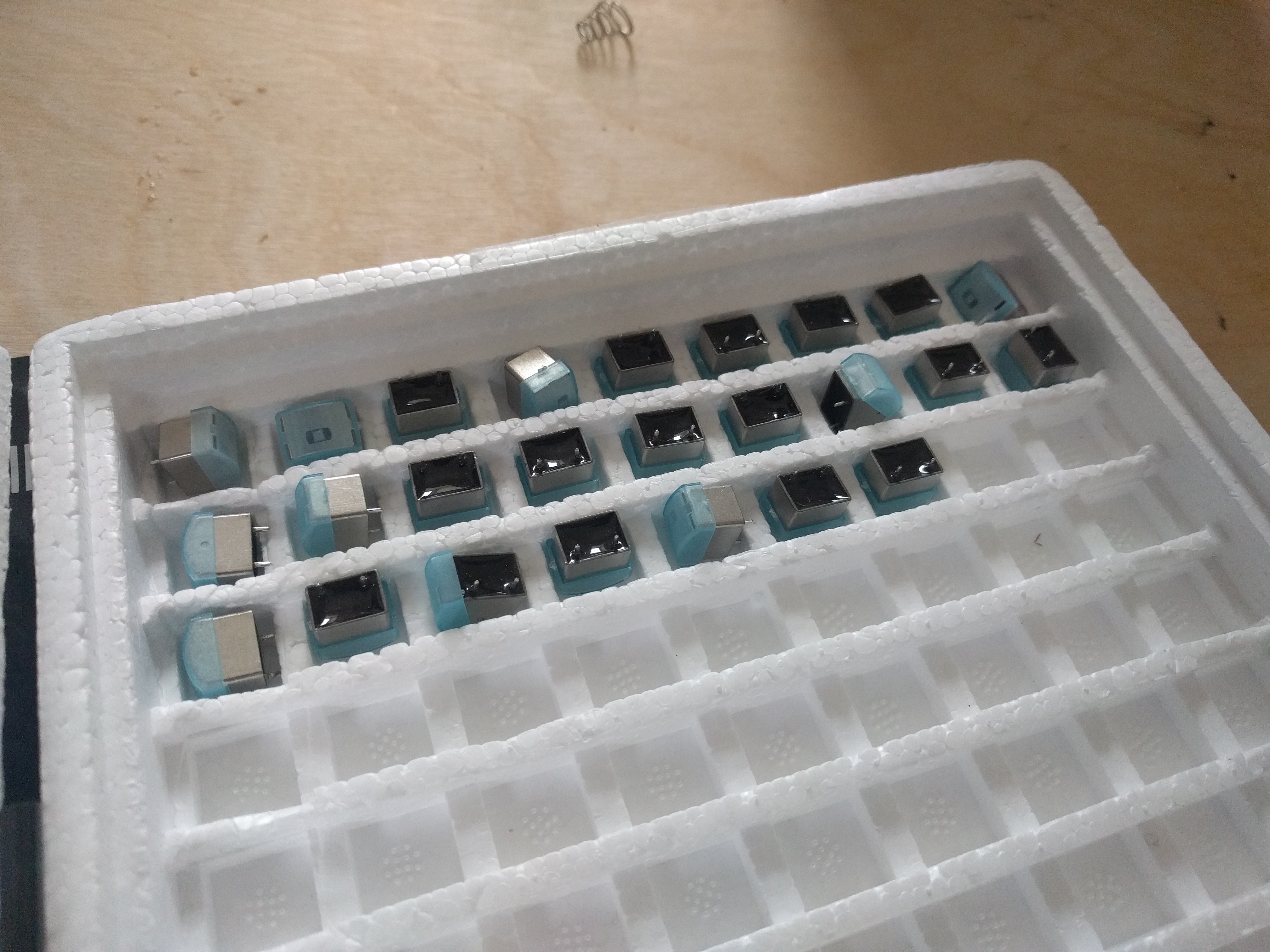
It's been a while since I did an update; I received the magnetic heads I ordered.
I've been collecting parts to prototype various amplifier circuits but got distracted learning about crystal radios, I know they don't seem related but there seems to be some relationship...
Anyways, various test circuits will follow.
-
Fork
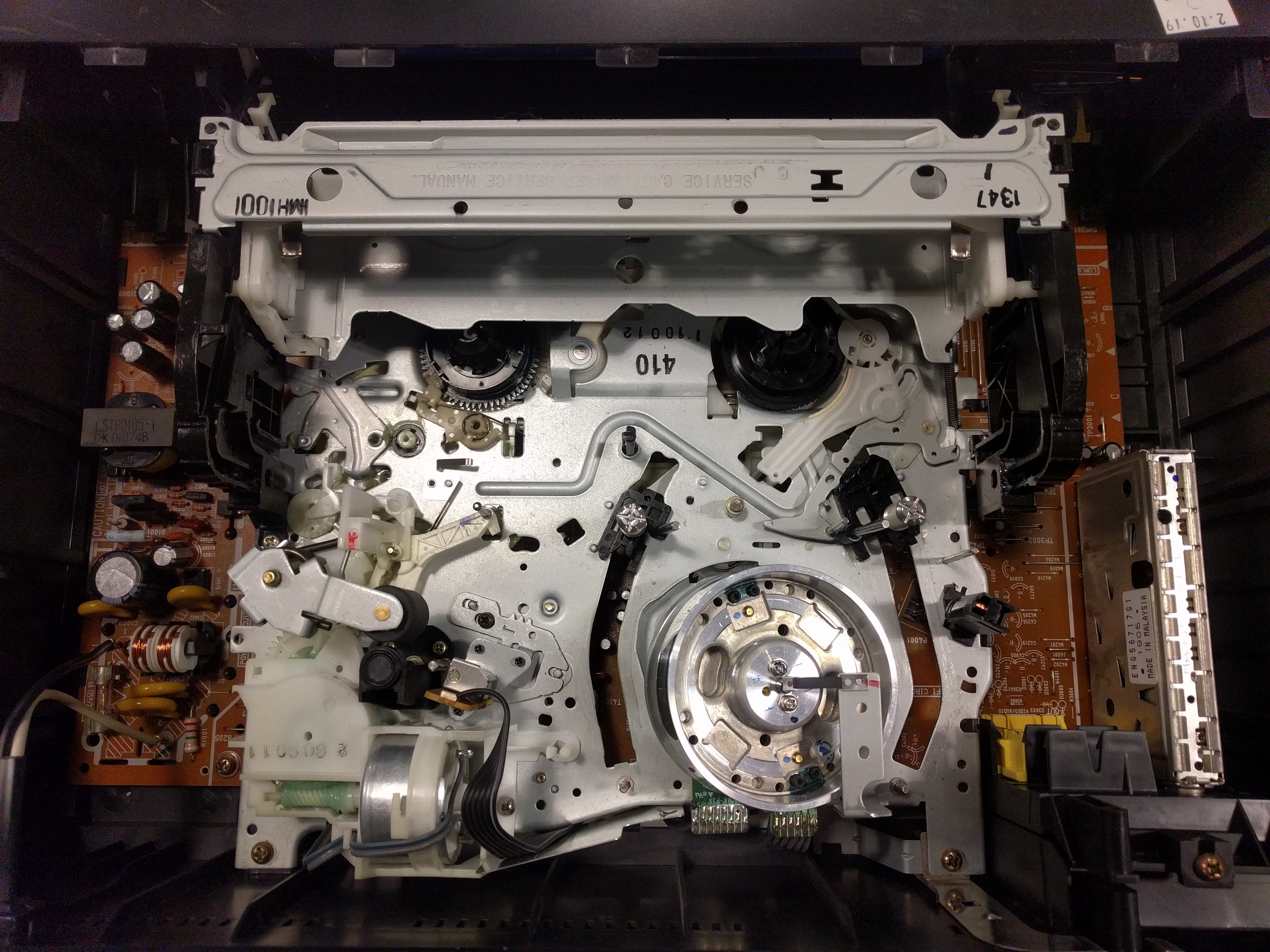
02/18/2019 at 14:13 • 0 commentsI think I made some noises a while back about wanting to do a similar project, but with a VCR for video.
Well, I started working on it; documentation can be found at: VHS EMF Project
![]()
Continuing with the cassette system, hold tight! Should be getting in components this week so I need to cobble together some test circuits. Assuming all goes well I will be able to compare their performance.
-
Quote
02/14/2019 at 21:28 • 0 comments![]()
Got the quote; the unit savings at this scale are small so I will likely go small to minimize risk at this stage.
Still planning on making a new board from scratch, so things are about to start getting interesting.
I've found a couple potential circuits so that's next.
I also got my hands on a VCR so that's been forked to another project of mine, hopefully crazy visuals? Going to check that out tomorrow.
-
Single element head info
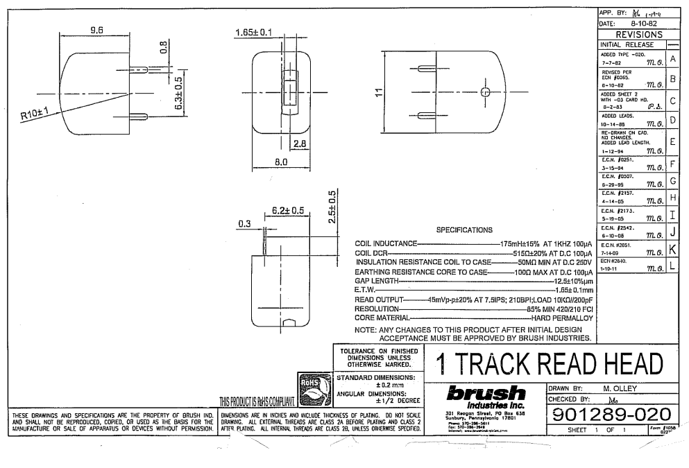
01/24/2019 at 18:48 • 0 commentsI finally got the specification sheet from Brush industries:
![]()
no price yet, likely dependent on volume.
So.... I guess I need to test an amplification circuit with my current coil heads and get a resistance reading to see if this would be compatible. If anyone has any advice on this please holler at me.
I recently learned about baluns and wonder if this might help in some way or be a way to completely side step this kind of specialized sensor by building a general purpose antenna.
-
Sourcing unusual parts
01/18/2019 at 23:26 • 0 commentsI called a company which manufactures tape heads today since that seems to be the hardest part of moving forward with this project. https://www.brushindustries.com/ fortunately seems to have something in stock and is semi-local. We'll see if this might work for this project, so hopefully they forward the needed documentation soon.
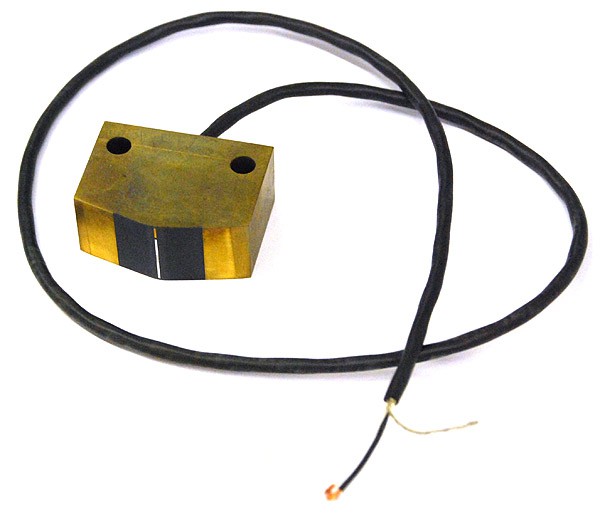
During the course of the conversation though I learned that some of the heads they make are pretty amazing, such as for this piece:
![]()
Apparently this is rated for 7 million swipes! But comes to the tune of ~$500 and is for transit systems and such.
Fortunately, they have something much more reasonable for our purposes.
I found some amplifier circuits and audio bits in the electronics bin and am going to fiddle around trying to kludge together something which makes noise but is smaller.
-
PCB Design
01/07/2019 at 19:57 • 0 commentsOkay; I'm doing it.
I still plan on fixing design files for previous designs but I'm going to try and make a new PCB for this thing. I keep finding contradictory information though, based off of the square reader it would seem that a tape head transducer could just be hooked up to an audio processor circuit and played, but its difficult (for me) to find decent plans for such a standalone contraption.
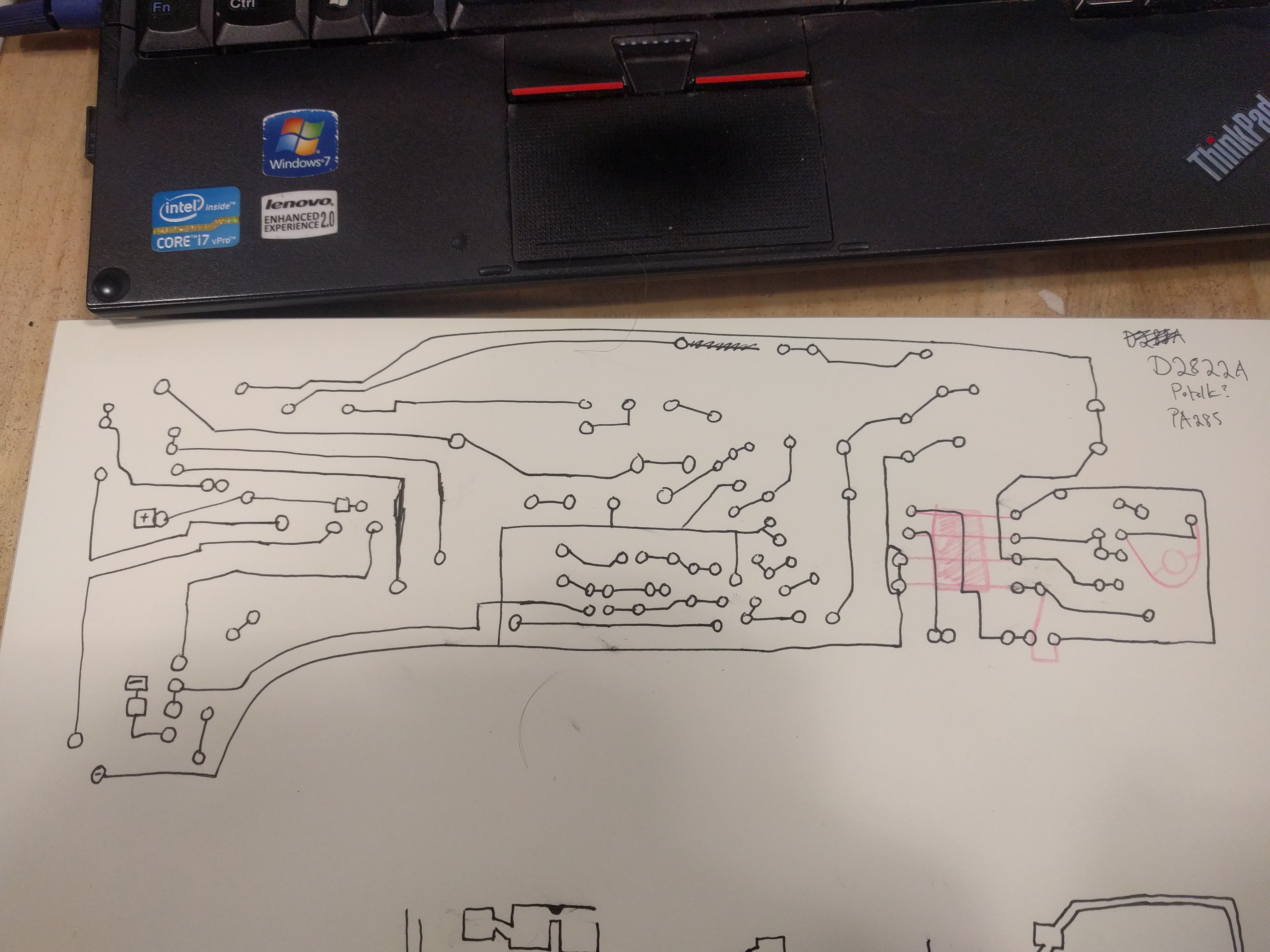
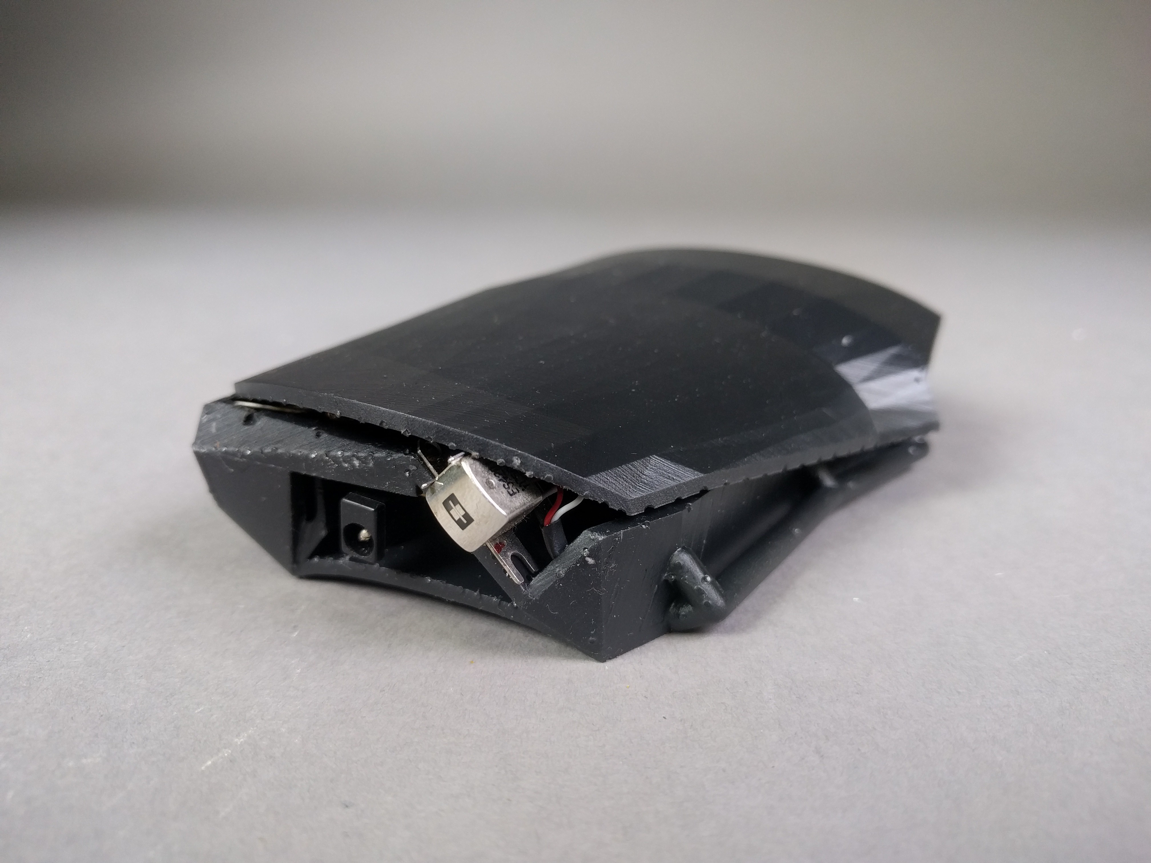
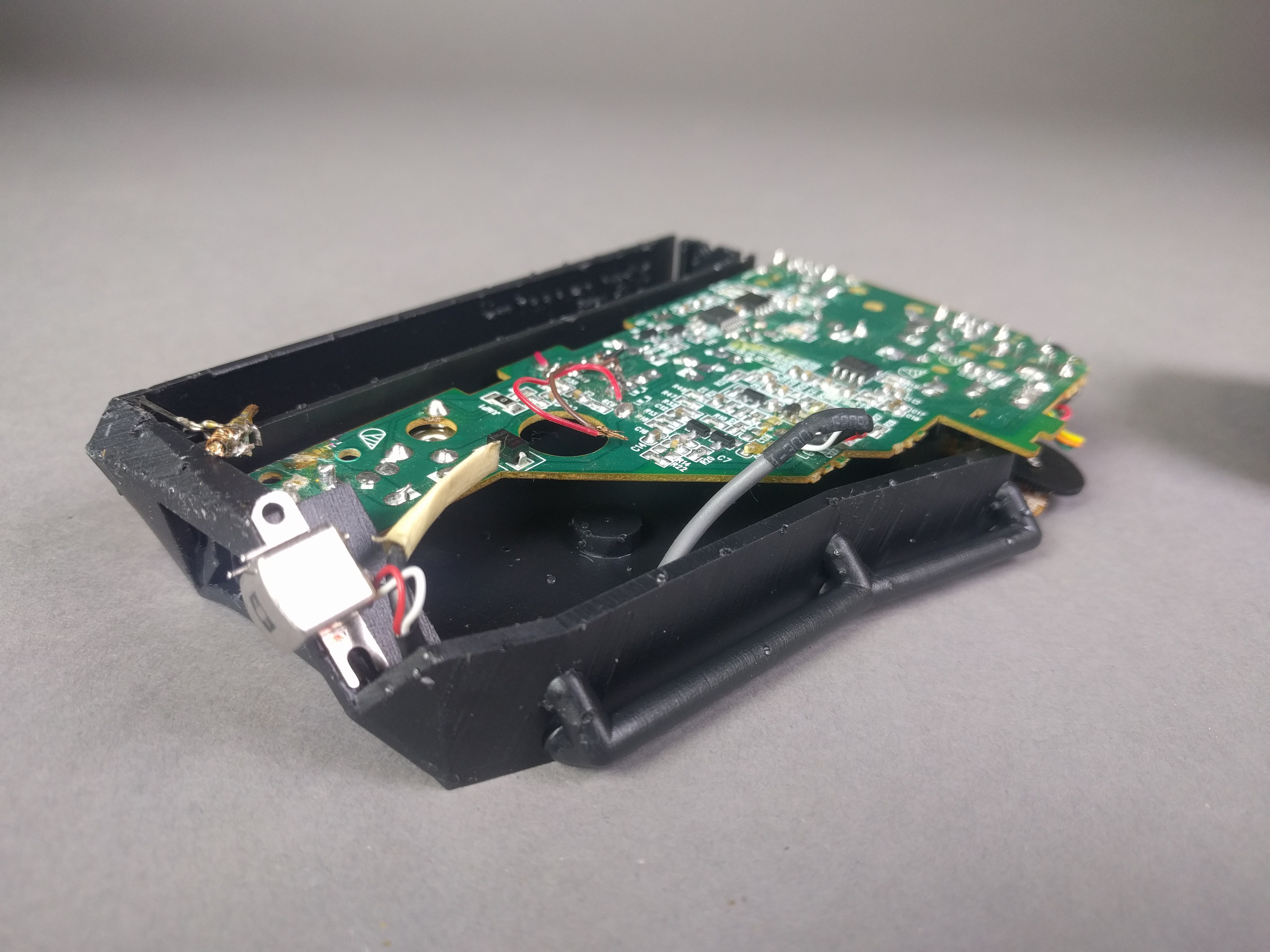
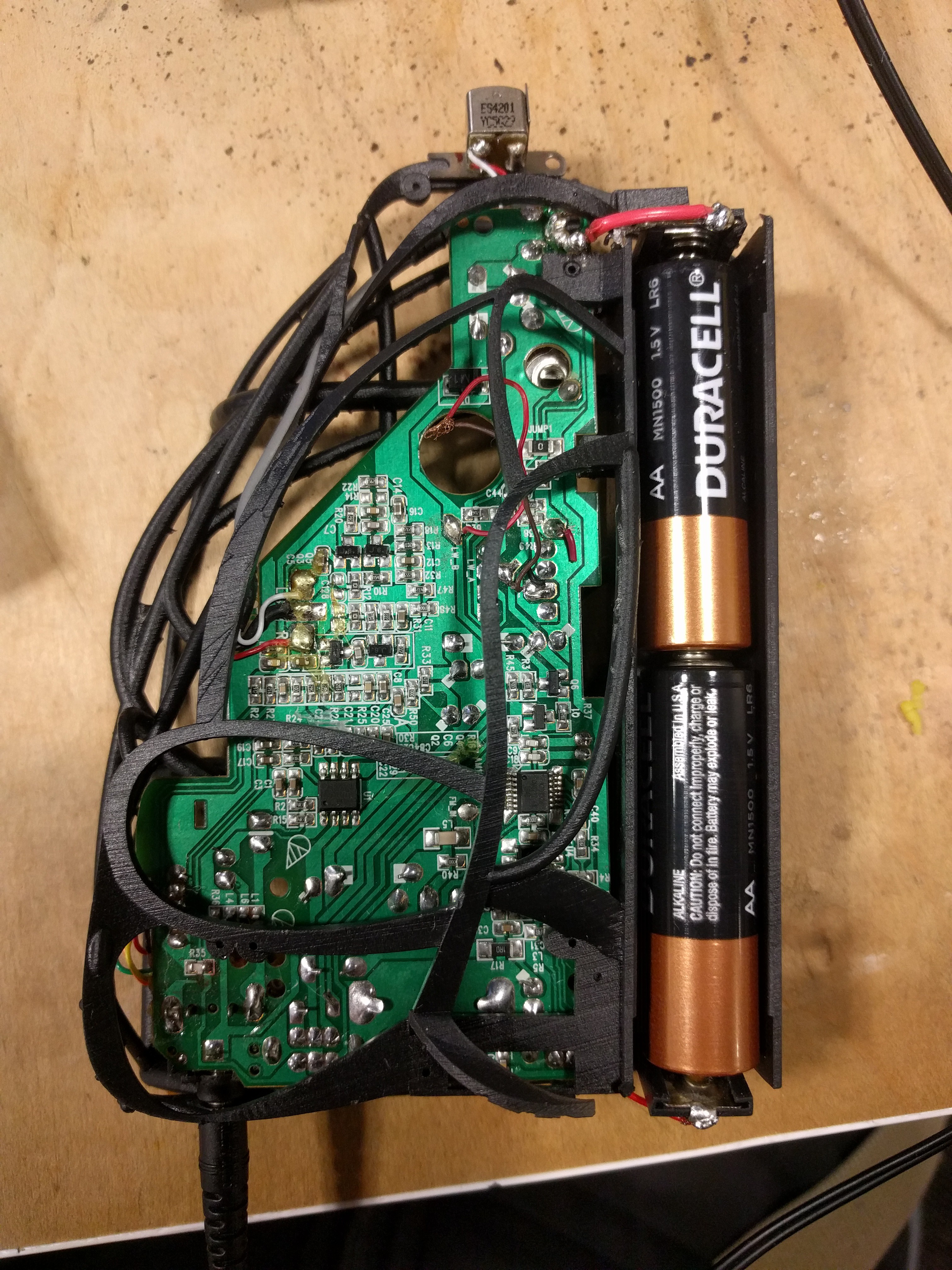
I started reverse engineering the MS 01-118S-01 board but almost immediately ran into a roadblock trying to find the read head.
![]()
And..... NO.
Fortunately I seem to have found plenty of alternatives to what they used:
http://www.durascanheads.com/standard/index.html
http://www.apolloelectronics.com/en/products_show_3_16_178553607.html
Again though, I don't really know which would be ideal other than that it should probably be single track... Although if it was two track it could potentially be used for stereo?
I know that I need to amplify this circuit and that the SCR uses the https://www.electroschematics.com/4375/tda-2822-stereo-amplifier/
Others have used the http://www.ti.com/product/lm833-n which is about $1 each.
On the processing end.... https://www.electroschematics.com/12327/simple-sound-processor-circuit/
Ultimately I'm not looking for any noise cancelling features, a delay might be useful but isn't really required.
The smaller this can be the better for obvious reasons, the current models are a little too wide in my opinion due to batteries and stuff..
Cool, so what does all of this mean?
This project is taking a step in a slightly different direction:
1) A new project page will be started soon detailing a preliminary design of a new circuit board and subsequent designs. This will likely take on the form of a kind of watch like processor and finger tip sensor section. This is a fairly ambitious undertaking as far as I'm concerned since I'm basically winging this.
2) This page will get updated with updated designs, but only for one board probably. I just don't see the point in working around the existing MS board, its too sloppy in its construction (sorry, but not sorry.)
3) A third project will likely spawn from the new board, assuming I can get it to work. This will be more oriented towards actual data acquisition and sampling rather than sensory augmentation.
-
The big update
01/04/2019 at 20:23 • 0 commentsOkay! Sorry for the delay; both cases came out okay and actually function BUT, as expected there are issues which will need to be fixed. For one, the Suntone board has clearance issues in both models so cannot be used, I think I just modeled the board too quickly and missed some features (it's a lot more sloppy in its construction.) The more solid version:
![]()
Note the extra space for future Suntone board and volume placement which will be carried over to the wire-frame case in later version.
![]()
And the more wire-frame version:
![]()
![]()
![]()
And..... A video of it working! Unfortunately with a pitiful speaker and video.
As you can hear... poorly, each light although appearing to be identical emits a different frequency likely related to power instability and rate of decay. The power cable for the light box emits a fairly constant tone that can be heard from most power cables. The printer has a touch screen, which obviously has a lot going on. A lot of samples could be collected just in one room.
Anyways, moving on to actual cases and technical stuff.
Realize that if you print these cases right now there will be a number of issues (although obviously not enough to stop you.) I will fix these issues between now and sometime next week, some other projects are occupying my time. Known issues at this time:
-Battery compartment should be unibody and sealed, the end tabs flex too much.
-Battery compartment needs larger overhang to retain batteries (note the hot glue in pictures.)
-Pilot holes for screws must be enlarged by 1mm.
-Remove more material around positive and negative battery connection to board, annoying to solder.
-Wireframe case needs to be taller to allow for Suntone board to slide in, too tight!
-Wireframe case needs volume relocated to left side as done with the solid, otherwise wires must be extended.
-Front-most wireframe element needs reinforcement.
-Rear-most batter side wireframe element needs removal.
-Solid case needs mounting posts for Suntone board.
-Solid case lid needs smaller secondary post removed/relocated.
-Solid case needs base and lid extended to the rear.
-Solid case needs larger side cut for board protrusion and volume reach.
I think that's it for now.
I'm thinking I'll put up both prototypes for sale on Tindie once they are more stable if anyone is interested, money will go towards next iteration.
-
Done printing!
01/01/2019 at 22:15 • 0 commentsBUT; I couldn't get into the lab today.
I'll update with photos, etc. tomorrow.
![]()
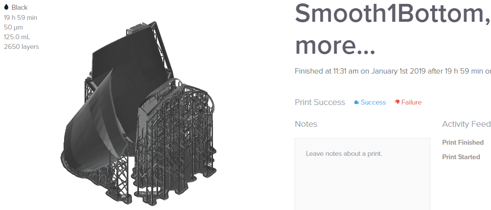
Yes, it took 20 hours to print both cases on a Form2 at medium resolution 0_0
Probably would have been way faster to do one at a time and with different orientation.
-
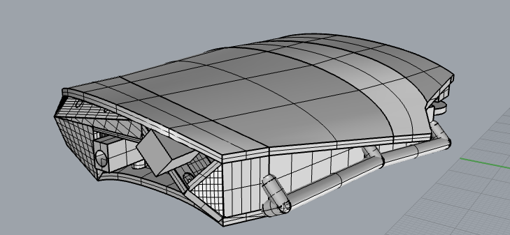
Another Case
12/30/2018 at 04:50 • 0 commentsThis one is for the SCR_68C PCB720 only (for now)
![]()
![]()
![]()
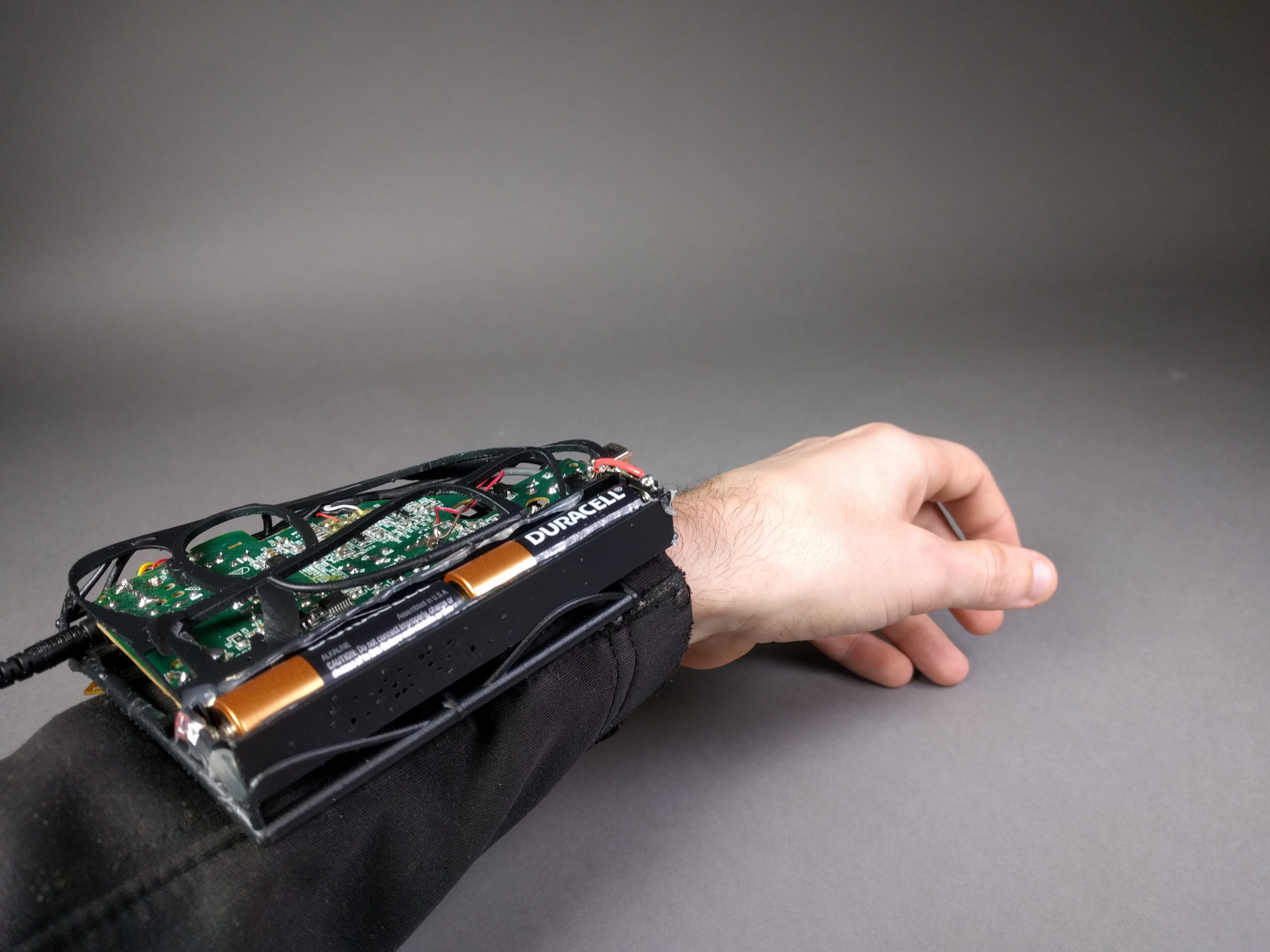
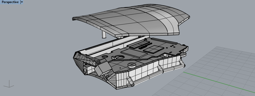
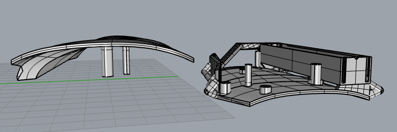
This is definitely a lot more material; I tried to hide mounting screws and the bulk of components. Sensor and volume have been moved to the left of the case. My thinking is that you are less likely to bump the sensor when flexing your wrist back in this case.
I again opted for an elastic band or velcro strap system for rigging.
Although this is much more... robust it will likely take less time to print and might use less resources than expected.
BUT, like the previous version I still haven't printed one myself to test.
My only real concern is the battery compartment which can thankfully be swapped out fairly easily. Besides that the drill hole taps might be a little small, but better smaller than too large when it comes to mounting hardware and I provided ample material to drill out further as needed.
Files are named Smooth1Top and Smooth1Bottom respectively. As usual, ask any questions if you have them! -David Troetschel
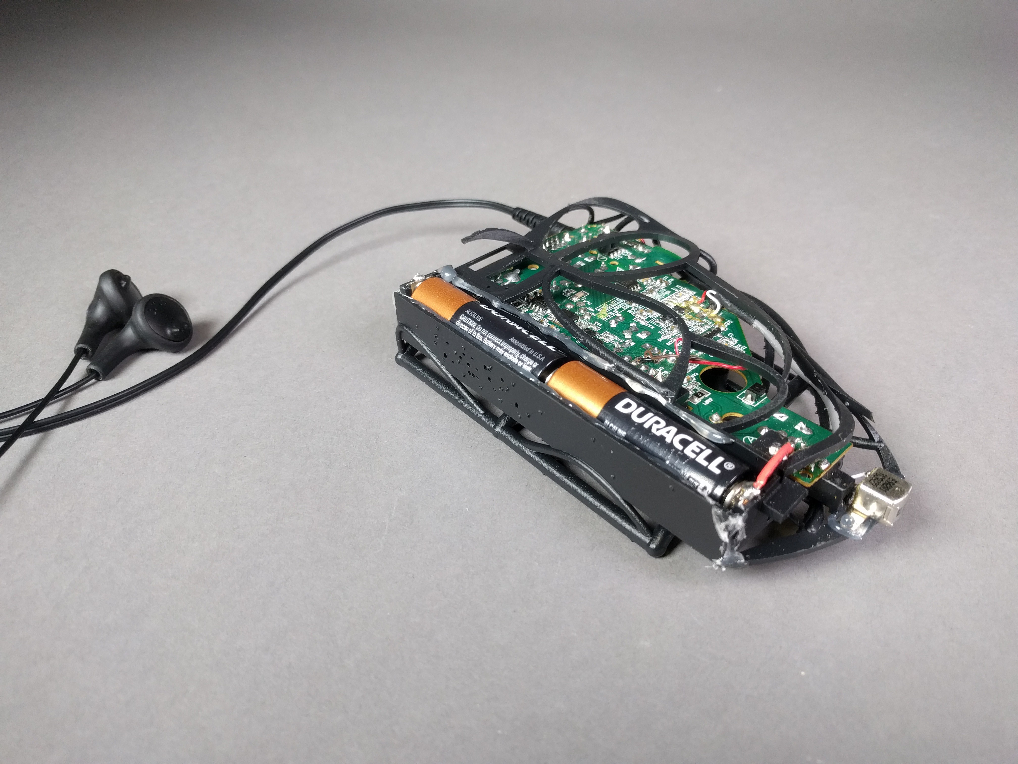
EMF Pickup Device
An enclosure for a hacked cassette player pickup and processor so you can listen to EMF waves
 I've been testing some circuits with a little success.