Amos
Amos-
Building Some New Colourful Blocks!
04/13/2019 at 08:32 • 0 commentsFirst up, an apology for the lack of updates since I received my last batch of PCBs. There have been a few things going on in my life that I am not willing to discuss here, but it has been a rather trying time. I have been focussing on my family and my studies (in that order) and all of my projects have taken somewhat of a backseat. I'm slowing getting back into the swing of things...
Secondly, another apology is due. I had recorded the unboxing of my PCBs and an initial investigation into the quality, but I am a doofus and the recording was all but unusable. The audio was ruined by a neighbour's intermittent, loud music and the video was affected by a big, clumsy doofus knocking the tripod. After trying to cut around the damage and re-record the voice over, I have decided to give up - it was taking me too long and I am not a videographer. I will try o chop what I have up and reuse some pieces if I can, but the whole unboxing experience was a non-event - sorry about that.
Some Colourful New PCBs...
As you may know, I recently received a batch of PCBs from JLCPCB, who kindly provided them free of charge. This was a great boon, because I am a (mature-age) student, currently living off student payments (Austudy) and as such I don't have a lot of disposable income. JLCPCB recently dropped the price of their coloured PCBs and I thought it would be neat to see how the colours worked for my program blocks. In my original prototype I used coloured breadboards to represent different programming constructs. For example, Red, Green, Blue and Yellow blocks were variables, White blocks were output blocks. Now that colourful PCBs are affordable, I could implement a similar colour scheme again instead of having all green PCBs.
![]()
I quite liked those colourful blocks, and have preserved a set of them for posterity. 8^)
At around the same time I had been experimenting with the ATTiny841 as a replacement for the Arduino Pro Mini clones in my blocks. The '841 is a neat little chip - it has two serial ports, which I can use for the incoming and outgoing connections, and 12 GPIO pins ('though I am using four of those for the serial ports). A bit of ugly breadboarding proved the chip was up to the task, so I decided to take the leap and use the chip in the next iteration of the design.
![]()
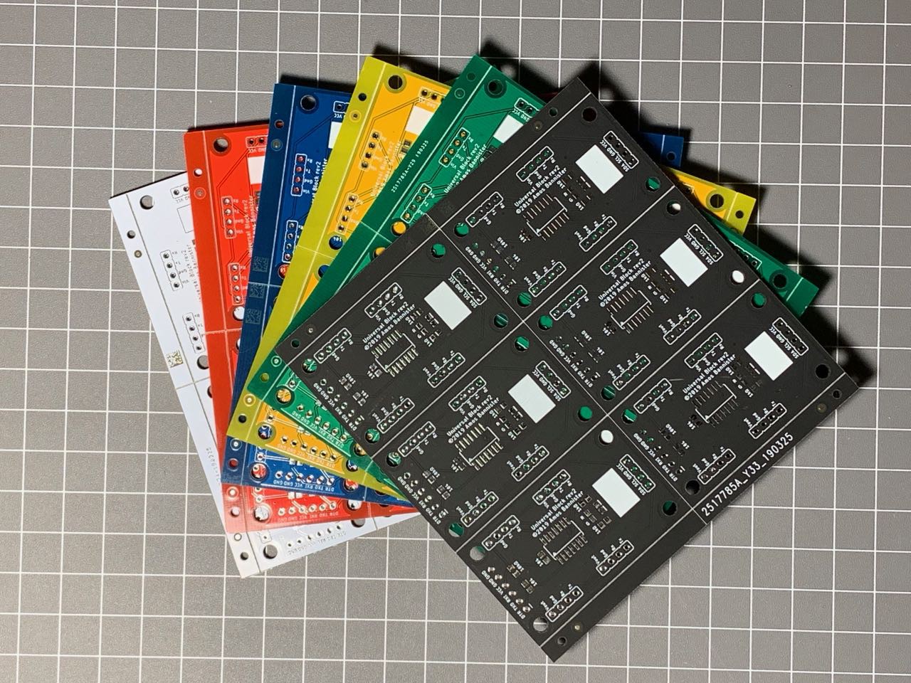
I somewhat cheekily reached out to JLCPCB via Twitter and their representative offered to pay for my next batch of boards, so I went about designing a new PCB layout using the ATTiny841 and placed my order for a small batch of five panels of each colour - Green, Blue, Red, White, Yellow and Black. The new boards would be quite sparse compared to the previous iteration - the '841 is much smaller than an entire Pro Mini and the reduced number of available GPIO pins (out of the 12 available, four are used for 2x serial, 2 for I2C and one for the reset pin, leaving 5 free) meant I had to drop the jumpers for the block id. The lack of block id jumpers means I have to hard-code each block's id, which is not that big a deal IMHO.
Unfortunately (for me) the '841 is only available in an SMD package, so I went the whole hog and used all SMD in the new design. I included an FTDI-compatible programming header on one end of the board so I could easily program the blocks when needed.
Examining the New PCBs
The new panels indeed looked quite sexy!
![]()
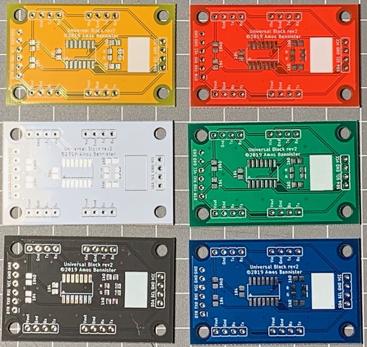
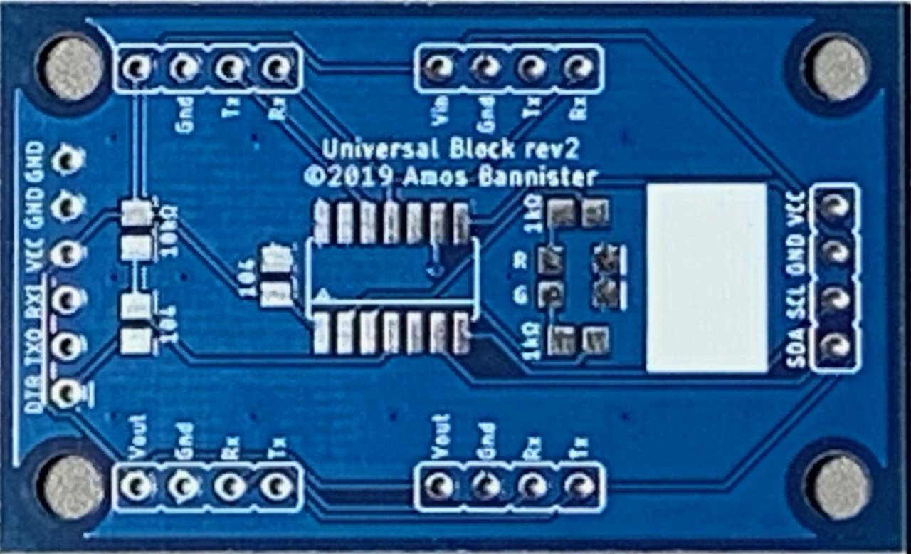
And breaking the boards apart leaves some very sexy, tiny modules!
![]()
And here is where I discovered my first mistake (thankfully a tiny one) - the Vin label on the first connector was missing. I don't know how that happened, but it is an easy fix.
![]()
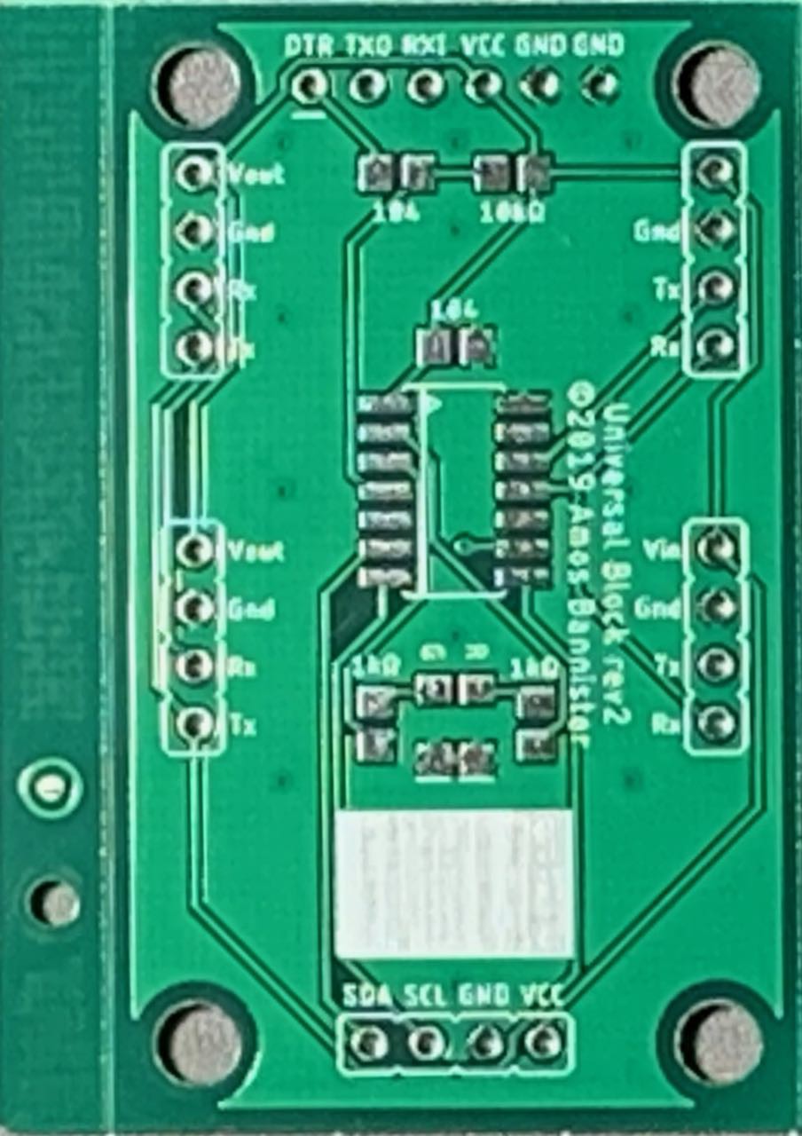
A close inspection of the boards showed them to be very nice. The matte black boards in particular look gorgeous, but all the colours are quite nice. One complaint I have however is the white silkscreen is a little streaky on a small number of the panels. This is really only obvious on the space I put for a block label (the white square at the bottom of the PCB below) and it only seems to affect a small number of boards. Still, it is not ideal. 8^/
![]()
A final note on the quality of the coloured PCBs: While the matte black is definitely a very nice looking PCB, I think I might prefer a glossy black to match the look of the other colours. Unfortunately JLCPCB no longer offer glossy black as an option. It would also be nice to have the option of a black silkscreen for the yellow PCBs - the white silkscreen can be a little hard to make out at times, especially for ageing eyes like mine. 8^P
Building the New Boards
Before I document the build procedure, I will state upfront that I have no intention of filming the build - you really don't want to hear a grown man curse the teeny-tiny, little SMT resistors and capacitors. Man those things are small and difficult to wrangle! >_<
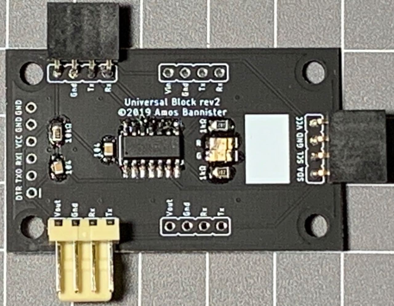
The first block I built was a black one - naturally. I had to get the sexiest one built and tested. I didn't use the stencil I had ordered for the first few builds - I just used a syringe to lay down some solder paste and then blasted it with my hot air gun after I placed the components. One minor issue with the black boards showed here - the flux residue looks bad on the matte black, but that should clean up okay with some IPA.
![]()
And here was where I discovered two other flaws in my design. 8^(
The first, most obvious flaw was the placement of the LEDs. I am not sure how I managed it, but they are too close. The spacing between the resistors either side was as it should be, but the LEDs had been moved in towards each other. I was able to solder them carefully, but they are a fraction too close for my liking. Checking my Eagle files I must have nudged the two components together at some stage and didn't pick it up in time. I have since fixed the layout in Eagle.
The second flaw is not immediately visible. When I went to program the ATTiny841 it became all too apparent - while I had the FTDI header, I didn't have an ICSP header to flash the bootloader. 8^(
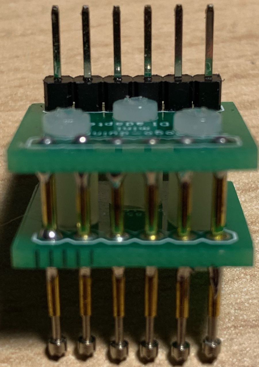
Luckily five of the six pins required for ICSP were available on the pins on the edges of the board, but the Reset pin was not so easy to get to. In the end I was able to hold a jumper onto the reset pin while I flashed the bootloader. It was awkward, but it worked. I am not sure if I will put a full, six-pin ICSP header on the next board, but I will at least break out the Reset pin. Then I will probably make a small programming adapter to plug into the board using the available pins already there.
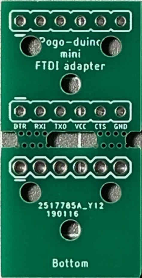
After flashing the bootloader (Spence Konde's ATTinyCore) I was able to upload my code using an FTDI adapter and a pogo-pin adapter I built.
![]()
I was somewhat surprised to see that everything worked as expected! In my excitement I decided to build another board - a white one this time. This time however, all did not go as planned. When it came time to flash the bootloader Avrdude just couldn't see the ATTiny841. I tried reflowing the solder, checked for shorts but nothing worked. I am not sure if the '841 was DOA or if there was another problem with the board. 8^(
Next I built a green board and this one worked perfectly.
After the two successful boards and one failure, I was not entirely confident, but I decided to push ahead and build a batch of boards. I broke out the stencil - it was HUGE! The JLCPCB stencil order form is poorly designed, with a drop-down list of stencil sizes at the top of the form and a "custom size" checkbox down the bottom. I had missed the custom size box and ordered the smallest preset size, which was about A3 size for a 30x50mm board!
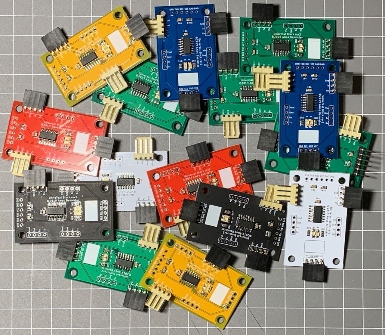
I rigged up a stencil holder and started applying paste to four or five boards. I populated the components and hit them with my heat gun. I manually touched up the LEDs to make sure they weren't touching, but all the boards turned out okay. I then made another batch of boards and I ended up with a small collection...
![]()
... And they all work, with the exception of the first white board I made. So, I'm pretty happy with the outcome here.
Design Flaws
While I am happy with the overall outcome, there are some flaws with the design that I want to address for the next revision. I will expand on these in a future log entry, but for now here's a brief list:
- Vin silkscreen error
- Need to breakout the Reset pin for ICSP
- Placement of LEDs.
- The LEDs are too close - need to be slightly wider apart
- I haven't really thought about the placement of the LEDs until now, but I think they prolly belong at the front of the board, between the FTDI header and the '841
- I2C pullup resistors should be on this board, instead I have them on the Value/Expression modules
- I should add headers (and an IO expander?) to the board to avoid the need for a separate Value module. Variable, Output, Loop, and If blocks all need a value (and optional expression) to operate, so it would make sense to incorporate the value onto the board.
The colours I am very happy with and I am generally happy with the ATTiny841 (apart from the Reset pin issue). There are some code-related issues I need to debug, but the project is definitely taking shape.
In future logs I will talk about some of these design flaws and how I might fix them, some issues I have encountered with the code and the other boards I received in the same order. Any questions or comments so far would be greatly appreciated. 8^)
-
Colourful PCBs!
04/02/2019 at 08:52 • 0 commentsAfter JLCPCB dropped the extra charges for coloured soldermasks, I decided to order a batch of PCBs in several colours to allow for quick and easy identification of program blocks. I (somewhat cheekily) pondered aloud on Twitter whether someone might sponsor this order - I am currently a student and even though JLCPCB's boards are cheap, when ordering six different colours of two designs, it still adds up. Alice from JLCPCB replied and kindly offered to cover the cost of the boards (and shipping!). 8^)
After trying the new, ATTiny841-based design on a breadboard, I finalised my new PCB layout and sent off the Gerbers. A week later a courier was knocking on my door with a nice big parcel. I resisted the urge to tear into the box and waited until I was able to film the unboxing (I need to tidy up the footage before I post it) and get a good look at the new boards.
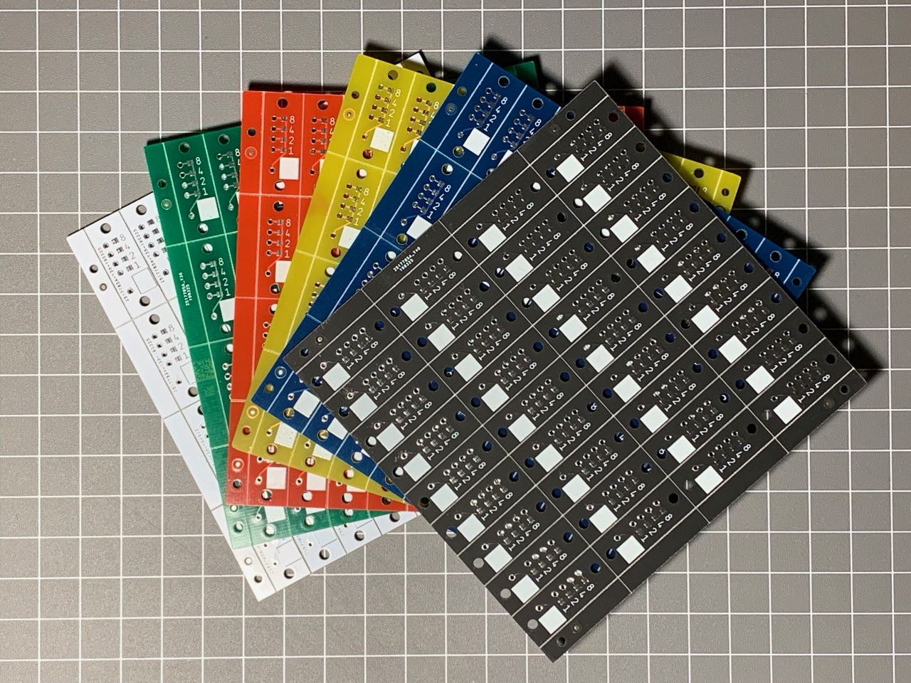
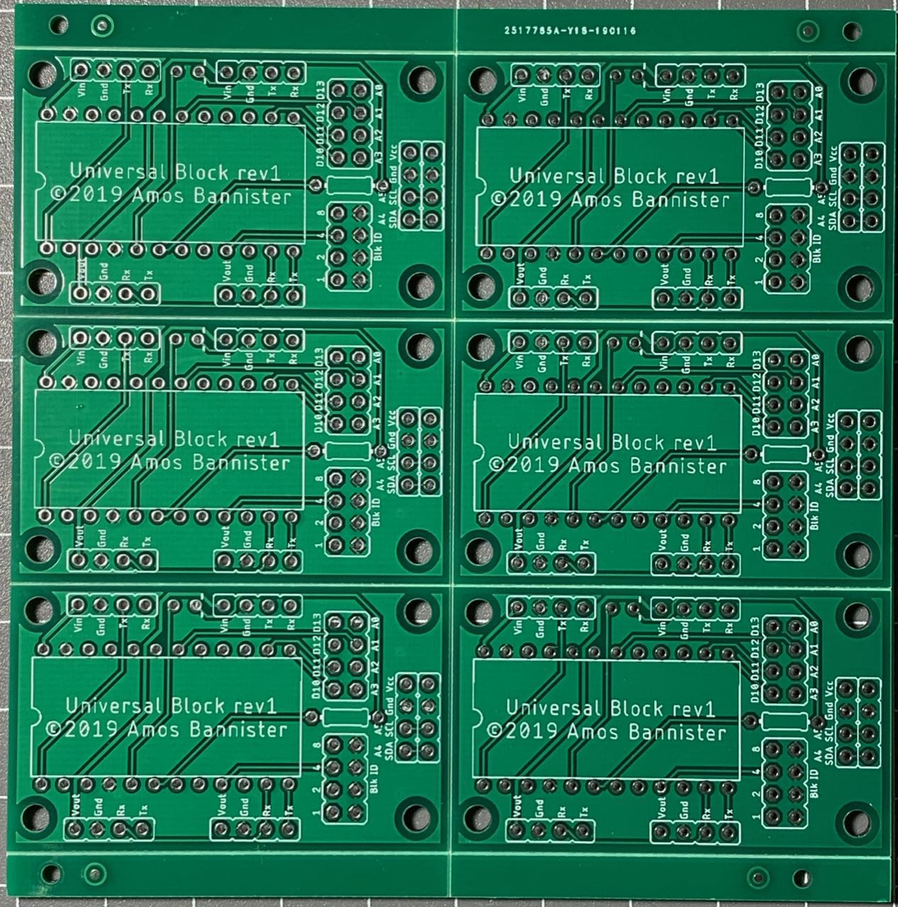
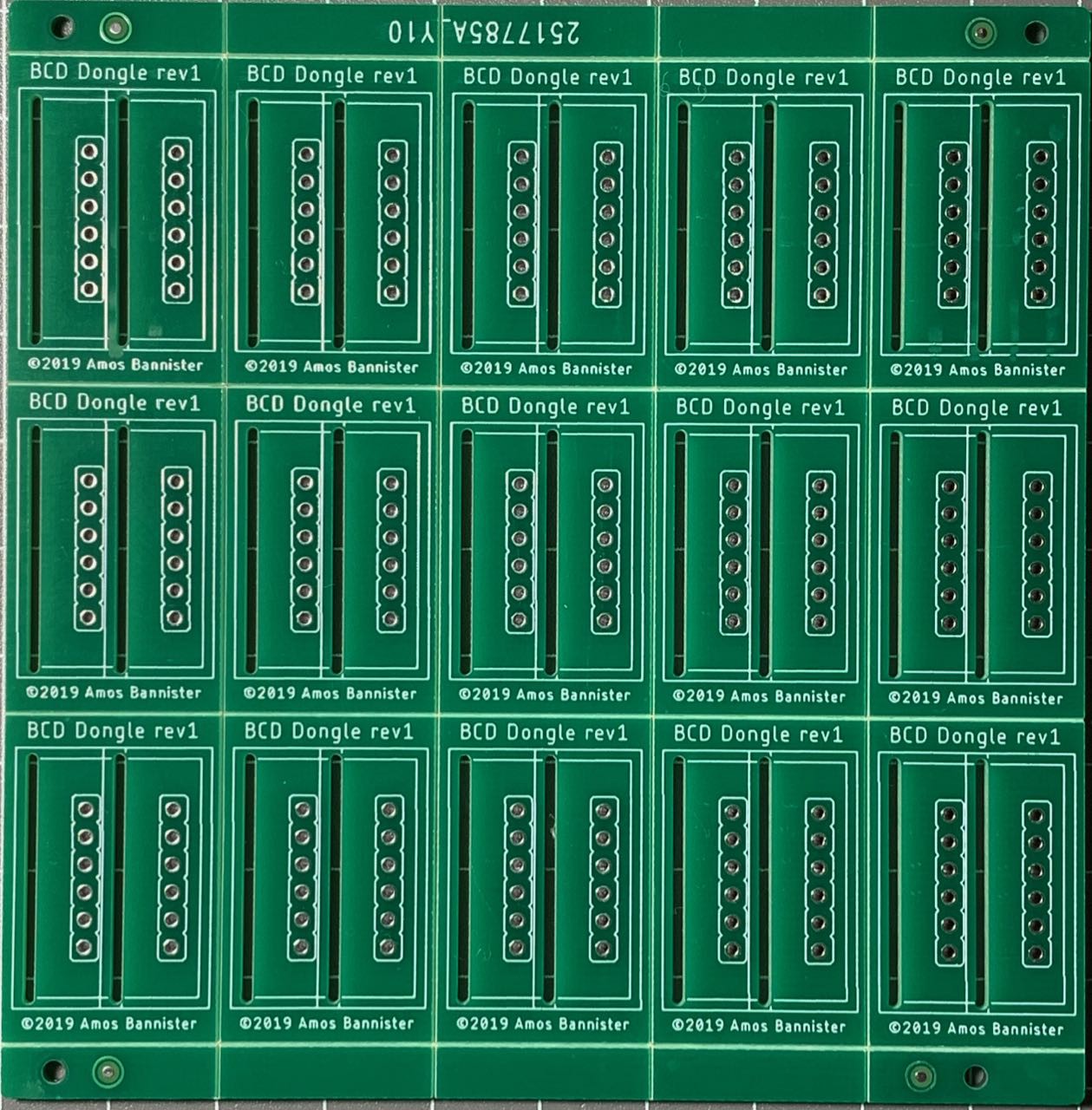
So far I am impressed. There are some slight silkscreen issues on a few of the boards, but overall the quality seems excellent. I will post a follow up with a detailed review of the boards and the results of a test build, but for now I'll leave you with two pictures of the boards...
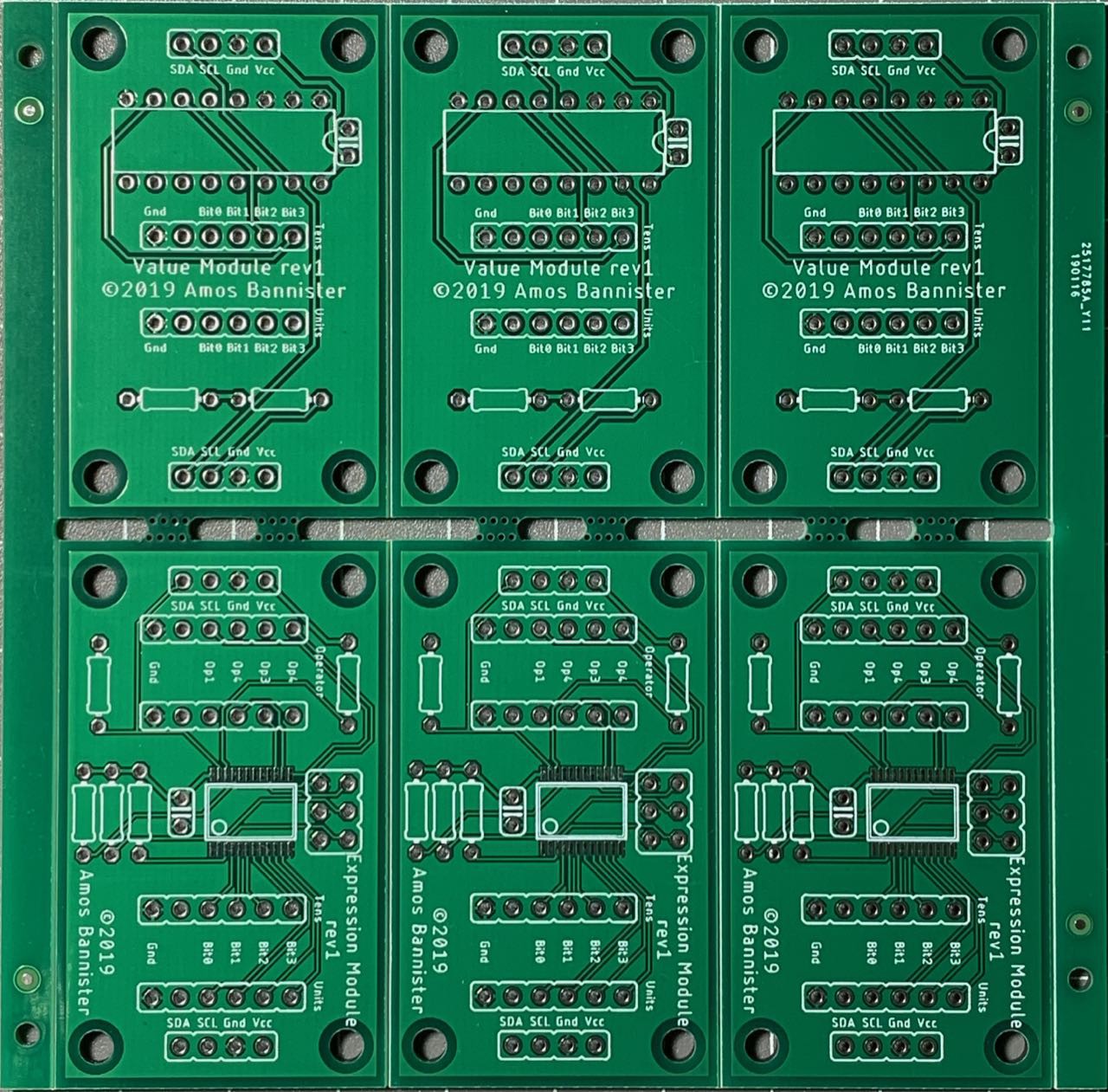
![]() And here are the digit/variable dongles...
And here are the digit/variable dongles...![]()
I can't wait to build some of these babies! 8^)
-
Using an ATTiny841 for the blocks
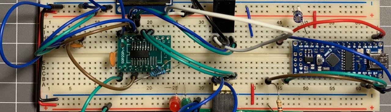
03/23/2019 at 12:22 • 0 commentsThe past week or so I have been exploring the use of the ATTiny841 for my programming blocks in place of the Arduino pro Mini clones I was using. There is nothing inherently wrong with the Pro Mini and they are cheap enough to use, however plopping a chip directly on the PCB will make for a more robust (and even cheaper) system. Brian Lough was experimenting with the '841 on his YouTube channel a few weeks ago and it looks to be an impressive little chip. It has 2 USARTs (which will be handy for the incoming and outgoing serial data for this project) and comes in a 14-pin package. SpenceKonde's ATTinyCore supports the chip and provides software I2C master support, although for now I am using an external library for the I2C. (I need to determine if I can change the default pins for the built-in soft I2C support - my initial attempts were not overly successful.)
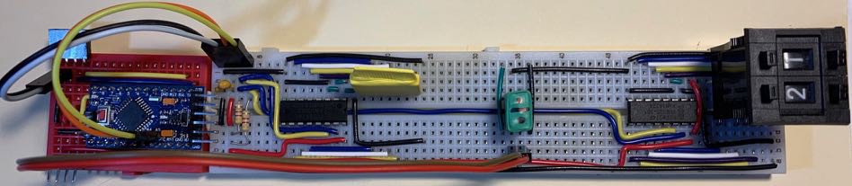
I successfully breadboarded an ATTiny841-based block today and happily it seems to work fine. It looks a bit messy on the breadboard, but looks aren't everything. ;^)
![]()
Now that I have the breadboard prototype working, it is time to commit it to a PCB. Due to the relatively low GPIO pin count, I have decided to switch to a hardcoded block id, which simplifies the PCB design. I'm keeping the same form factor as the Pro Mini based design and the final product will look quite stark in comparison! Apart from the connectors, everything is now surface mount. This was not an easy decision for me, as I am through-hole through and through, but the '841 only comes in an SMT package and it just felt odd surrounding the SMT chip with a couple of THT capacitors and a handful of THT resistors and LEDs.
With luck I will be able to get these new PCBs in multiple colours so I can use the board colour to visually identify the block function. (NB: I envisage the final version of this product will be housed in coloured cases, with each case having a different shape , so the function of a block will be identified by colour and shape (and possibly texture?) so as to cater for colour-blind users. I also want to key the connectors based on block type if possible so it will be difficult (or impossible) to plug the "wrong" blocks in to each other...)
-
Thinking about PCBs and colours...
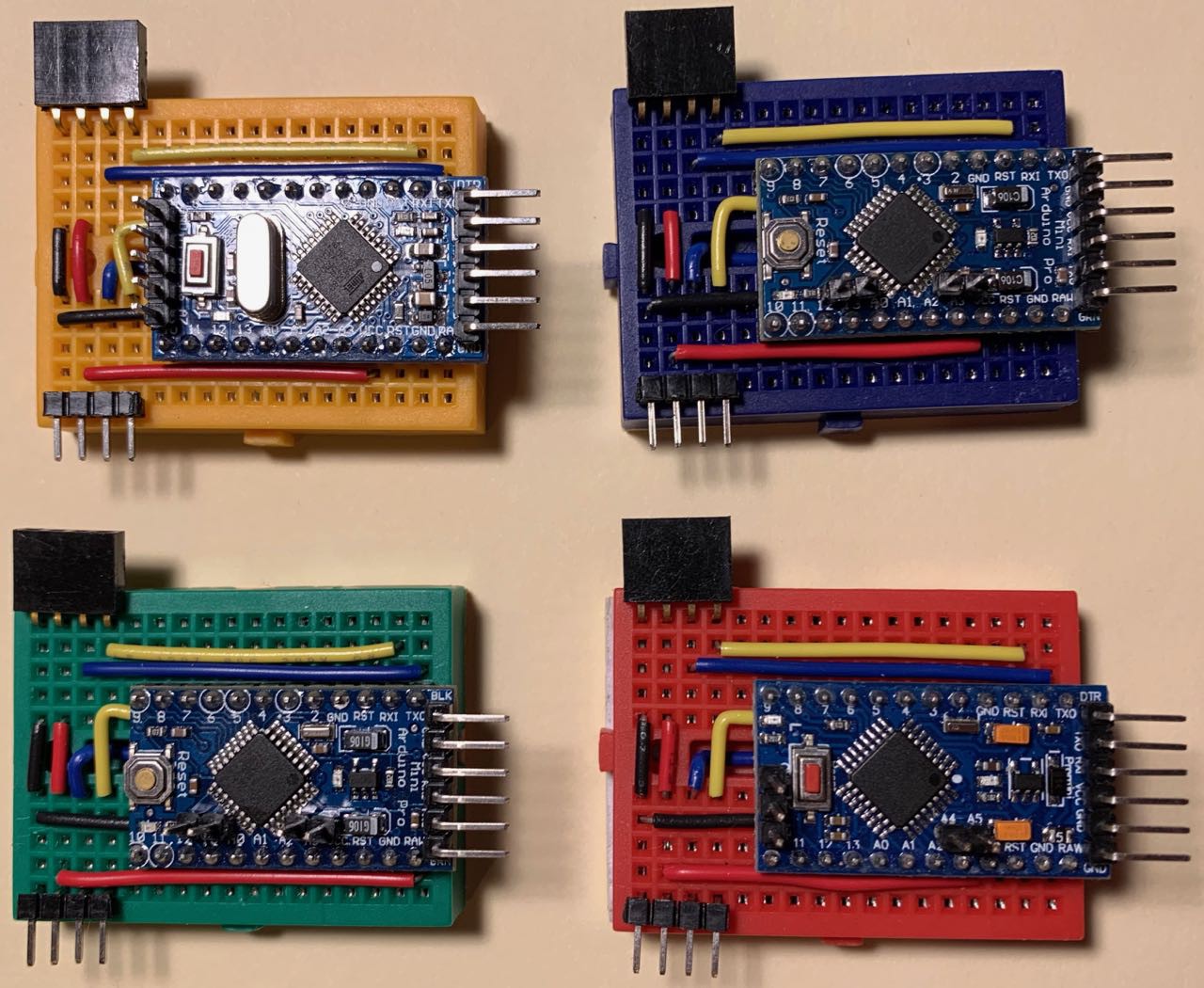
03/17/2019 at 10:40 • 3 commentsWhen I started this project, it was simply a university assignment. I had no thoughts of taking it any further than just enough to get a decent grade. However, as I started preparing prototypes and experimenting with different options I realised that there was some serious potential in this concept. This could form the basis of an interesting way of teaching kids how to program in a very tactile manner. I was lucky in a way, that early in the prototyping stage I realised that the mini breadboards I had were almost the perfect size for the modules. And by "almost the perfect size", I mean they were exactly one row of holes larger than I needed. (Notice the empty row of holes between the Pro Mini and the four in/out pins.)
![]()
The perfect sizing immediately introduced the idea of using colour to distinguish the programming blocks. The mini breadboards I had came in six different colours - yellow, blue, green, red, white and black.For my prototype I chose yellow, blue, green, and red as variables, white for output and black for "end program". (I also used slightly longer breadboards for loop/end loop as I needed some extra rows to "indent" the code blocks.)
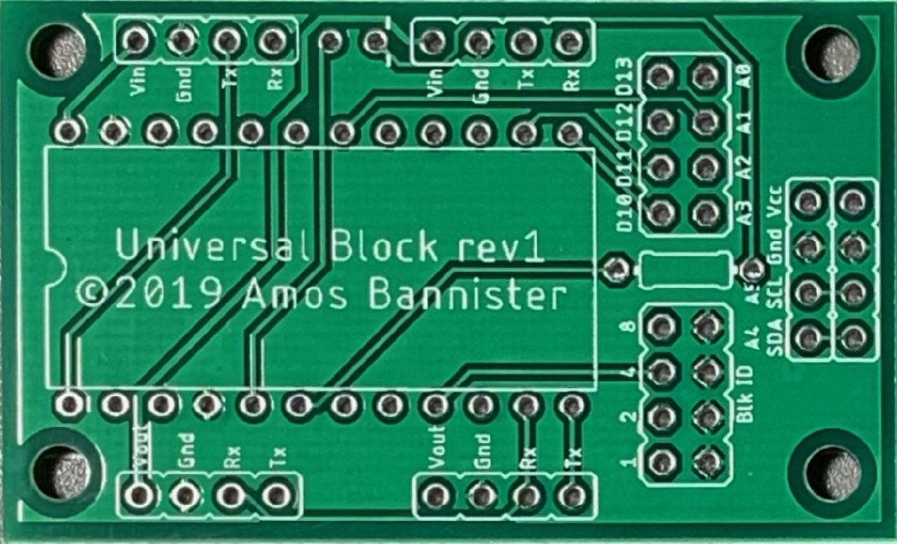
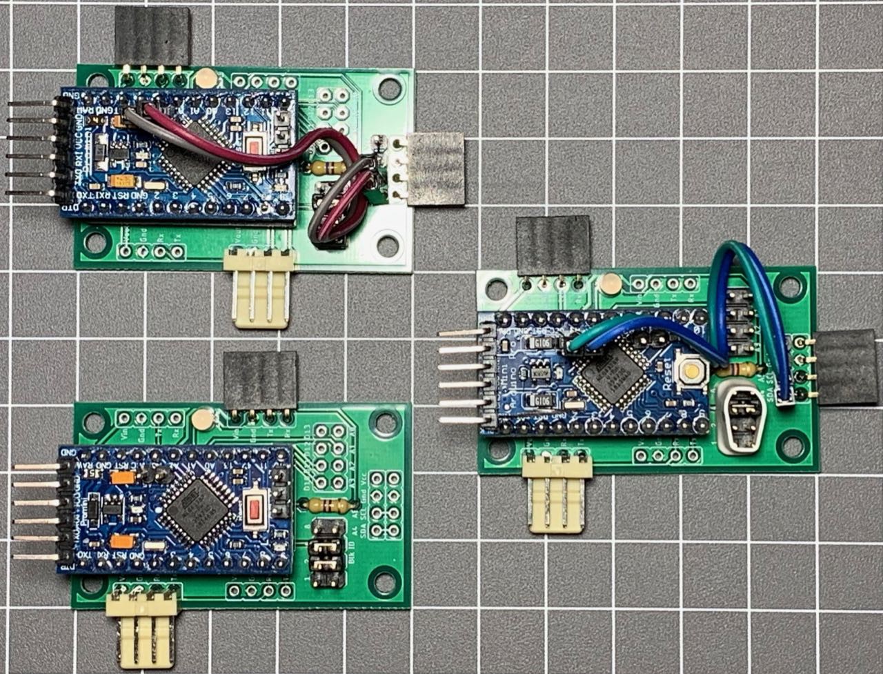
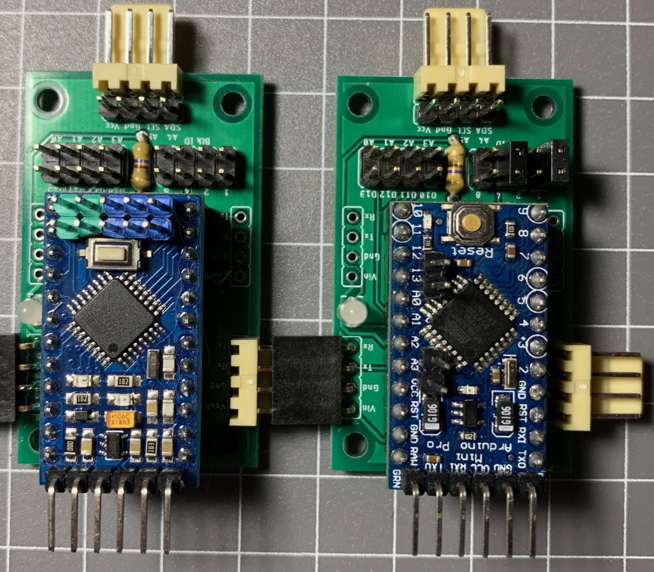
I liked the idea of colour-coded blocks, although using distinct colour blocks for each variable is a little hinky, but it worked well enough for the prototype - I am now considering having a single variable assignment block that takes a dongle to indicate which variable it is modifying. When I made my first batch of PCBs for this project (one problem with the breadboard prototypes was the four pin male/female headers are too easy to rip out of the breadboard) I had to (temporarily) ditch the idea of colour-coded boards. Instead, I planned to eventually create colourful cases for the blocks. JLCPCB (who I used for the PCB fab) do offer coloured soldermasks, but the cost was prohibitive for my meagre budget - effectively doubling or tripling the cost of the PCBs just for choosing colours other than green. Instead I chose plain green and to further reduce costs I made my boards multi-purpose. The boards have a socket for an Arduino Pro Mini, two sets of input pins at the top so you can choose to "outdent" code (for example, an ELSE, or END LOOP block), a corresponding pair of output pins at the bottom to optionally "indent" code (LOOP or IF blocks), a set of block ID jumpers to set the block type, I2C output pins at the right and jumpers for any spare GPIO pins "just in case".
![]()
![]()
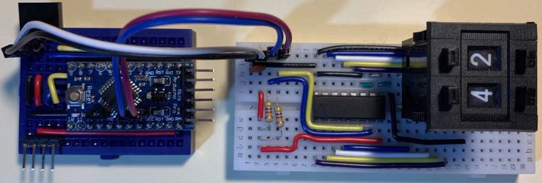
Adopting this approach has allowed me to drastically reduce the costs of the PCBs - one design can be used for almost any block type. However, while I only need a single PCB design for the blocks, I need ancillary modules for values, expressions and other block-type-specific functions. As I design later revisions of the PCBs, I am moving towards having distinct designs for specific types of block. Variable assignment, IF and LOOP blocks all require a variable and/or expression - for these blocks it might be best to build-in the initial value component and then allow the addition of an expression module to build up more complex expressions. I have started down this path and while I lose the "universality" of the blocks, it allows me to think about custom code for specific module types and offers some other advantages. I have a set of PCBs designed along these principles and I do think this is the right path to take moving forward. The block below has an integrated MCP23008 and headers to plug a value or variable dongle into. (I realised after I had soldered up this batch that I didn't need to MCP23008 - I could have used the broken out GPIO pins A0-A3 and D10-D13 instead - doh!)
![]()
My next step will be to remove the Pro Mini and use either an Atmega328PB (this variant has two UARTS!) or an ATTiny841 (again - TWO UARTS!) soldered directly on the board. Removing the universality (or limiting it to a degree) and using custom firmware for each block type (so I can remove the Blk ID jumpers) would allow me to reduce the size and complexity of the boards. Of course, it also means more different types of board, which will increase the PCB fab cost, but I think I have come to terms with that idea now.
Which, in a roundabout and meandering way (as is my wont) beings me back tot he thought of coloured PCBs. JLCPCB has just removed the extra cost for coloured PCBs, so a batch of 10 boards is now $2USD for the first design ($5 for subsequent designs in the same batch) in any colour (green, red, yellow, blue, white or black - the same colours as my mini breadboards). Maybe I won't get the program block boards in too many different colours, but I could definitely get some variable dongles in the different colours.
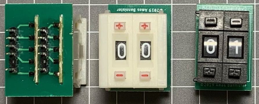
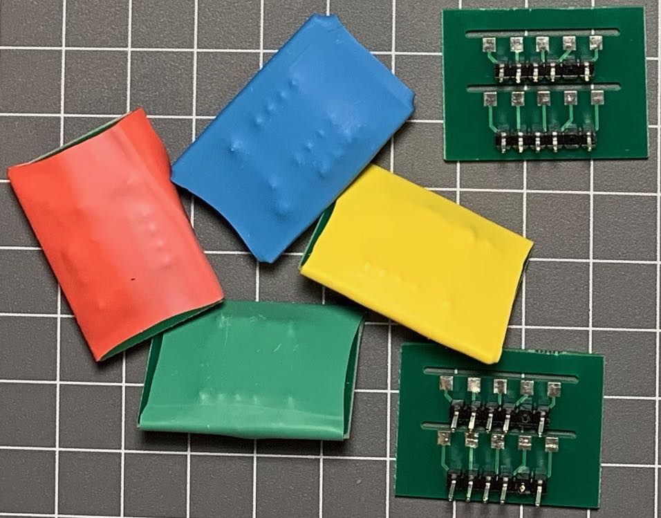
Did I mention my variable and value dongles yet? I have been using some BCD thumbwheels for numeric constants and have a small PCB to mount a pair of wheels so they can be plugged into a value block (or the combined board above) and read via a GPIO port extender. I think they are quite nifty, if a little expensive to source. To represent variables, I am currently using the same PCB with some jumpers soldered to hard-code a value (10 or greater, so it is easily recognised as being different to a regular decimal digit) and then use heatshrink to identify different variables. This scheme works quite well, but I am considering dropping the thumbwheels and use a modified dongle PCB with jumpers for digits from 0 to 9. Not as neat as the thumbwheels, but a darn sight cheaper. ;^) I could very easily get a set of dongle PCBs in each colour and avoid the ugly heatshrink...
![]()
![]()
So, I guess I need to make my mind up whether to get some coloured block PCBs or just the coloured variable dongles. If I do opt for coloured blocks, which colours for which block types? How many unique block designs will I need? Will the ATTiny841 work for this project, or will I need to extra memory/pins of the 328PB? And finally, how will I pay for all these new PCBs? Any want to sponsor a university student making pointless electronics? ;^)
-
Building and Coding the Initial Prototype
03/02/2019 at 12:19 • 0 commentsI mentioned earlier that this project started as a university assignment. For the assignment, I chose to implement a small subset of the language I had defined, namely: Variables; Output; and Loop/EndLoop. To simplify detecting the end of a program I also included an END_PROGRAM block.
For the variables, I used the four brightly coloured breadboards in the mini-breadboard pack I had. That gave me an easy way to refer to the variables - use the colour of their breadboard - giving me four variables, Blue, Red, Green and Yellow. The four variables defaulted to a value of 0 and could be assigned the value of another variable, a two-digit integer, or a simple expression comprising two operands and an operator.
Output was quite simple - it would output the value of a specified variable.
Loops could be programmed to repeat a set number of times.
For both Output and Loop, their input parameters were dongles I created to represent each of the four variables. These dongles could be plugged into the breadboard of the Output/Loop module and read via the relevant GPIO pins. As a shortcut, I allowed variables to assigned using the same system, avoiding the need for too many PCF8574-powered value blocks and expression blocks.
While it added complexity to the Arduino sketch, I decided to use a single codebase for all the programming blocks. Therefore, when a block is first powered up, the code checks for some jumpers on three GPIO pins to determine the block's type which is stored in a block_id variable. Then it checked to see if there were any I2C devices at addresses 0x20 and 0x21 - the addresses of the PCF8574 ICs. If only one device was found, that must be a single value module, if both addresses were found we have a full expression module. The block then enters its loop() loop, waiting for any incoming messages on both the hardware serial port and the software AltSoftSerial port.
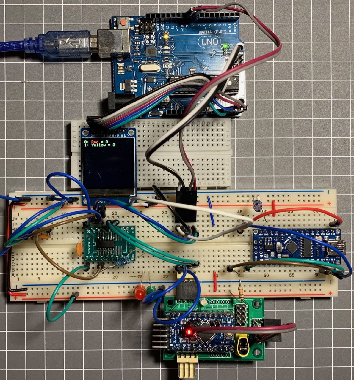
The master controller (I used an Arduino Uno with a small OLED display for this) would send a broadcast message (WHO_IS_THERE) on the serial port asking any attached modules to identify themselves and then enters its own loop() to wait for any replies.
When a block receives a WHO_IS_THERE request, it will respond depending on its internal block_id:
- Variable blocks determine their value by reading values via the attached PCF8574 IC (if any) or if no PCF8574 is detected they will read the value of a dongle plugged into the breadboard using GPIO pins. Having determined the current value of the variable (or its expression), a response is sent to the Master Controller containing the operands and operator of the expression, or a single value as appropriate.
- Loop and Output blocks responded with their block_id and their associated value.
- EndLoop and EndProgram blocks simply respond with their block_id.
After sending the WHO_IS_THERE command, the Master Controller waits for responses until it receives an EndProgram, storing the block_ids and their parameters in an array. Once the EndProgram has been detected, the Master Controller switches to execute program mode.
To execute the program, the Master Controller steps through the program array, interpreting each command as it goes, maintaining an internal representation fo the four variables. To indicate the progress of the execution, the Master Controller will instruct the currently executing block to display its green LED. All Output commands cause the respective variable's name and value to be displayed to the attached OLED display. Execution continues until the EndProgram block is reached, or an error is encountered. If an error is detected, the relevant block will be instructed to blink its red LED to let the programmer know where the problem is.
And that is pretty much all there is for now. The blocks are really only "dumb" placeholders and all the smarts lives in the Master Controller.
Postscript:
Since the successful completion of this initial prototype I have created some PCBs to build some more permanent, robust modules. I have also been giving some thought to how I would improve the code. I have also given some detailed thought into how I could improve the hardware. On the hardware front, I am still using Arduino Pro Minis (they are dirt cheap) but I am considering making custom boards based on either the Atmega328PB or ATTiny841 chips. These chips have two hardware serial ports, which will make the bi-directional communication easy and are relatively inexpensive. Moving the ATTiny841 would mean I will have to move away from a single codebase for all block types, as the size of the code is becoming a bit too large to fit in such a small device. I don't think this will be a huge problem - the communications protocol is already in a library, so I could create a library for the common module operations so I am not doubling up on too much code.
One big software change I want to implement is I want to flip the program execution on its head and have the blocks take control of their own destiny - calculating values and updating the Master Controller as appropriate. The blocks could pass an "Execution Token" around to indicate which block is currently executing. The output could be handled by having an Output Controller, which has an attached display. Each Output module would then send a message to the output controller, telling it what to output. Similarly, an "Input Controller" could be added, allowing for user input via a keypad or other device. This would allow for interactivity during program execution.
When I get some spare time I will be playing around with my first (and second) batch of PCBs and will update my explorations, however I am about to start a new semester at university, so free time may be a bit tight for the foreseeable future...
-
Defining the programming language
02/25/2019 at 05:00 • 0 commentsSo far I have explained how I connected the modules together and got them talking. There is one more significant piece of hardware I need - a way of setting values (constants) and creating expressions, so the programmer can create some code like:
x = y * 3
Or even just simply, specific a number of times to loop, as in:
for x = 0 to 3
First however, I should step back and spend a bit of time designing the programming language that we are creating. Knowing what form the language will likely take can help inform the design of values and/or expressions.
My initial aim for this project (apart from satisfying the requirements of my university course 8^) ) was to create a tangible programming language that could be used to teach children the basics of programming. One of the keys will be to keep the programming language as simple as possible. I decided that strings would end up getting too messy - how would the programmer create constants? And how would I hook up a keyboard and display to an Arduino to allow entry of strings (and other data)? How will the string handling work? What string functions should be included? That's all too much for now.
So to simplify things, I decided that the programming language will only support numbers. Simplifying even more, I am initially only going to implement integer values. A final simplification, considering the target audience's age and likely mathematical ability, I will keep the numbers to two digits.
Supported Datatype(s):
- Integer - initial values ranging from -99 to +99
That seems like a reasonable compromise for now. When this is all working, floating point numbers (aka decimals) can be added and after that, strings could be considered.
The next question is: What types of programming operations will the language support? Obviously we need some way of setting and manipulating variables. Given that this is only a learning tool, I figure that we could implement a limited number of pre-defined variables. Each variable could be represented by a colour. I had some red, blue, yellow and green mini-breadboards, so I arbitrarily chose those colours to represent four variables. If I add more variables, I can pick some other colours later.
There also needs to be some form of looping construct; a way of displaying results of calculations; and finally branching. Future additions could include functions, extra input/output options; and perhaps even integrating with Arduino modules and sensors.
Supported Programming Constructs:
- Set/change variables
- Loops
- Output
- Branch (if/then)
With this basic language specification in mind, how do I implement it? The main language commands can be implemented by a programming block, which we already have talking to one another. Setting variables will require something extra however.
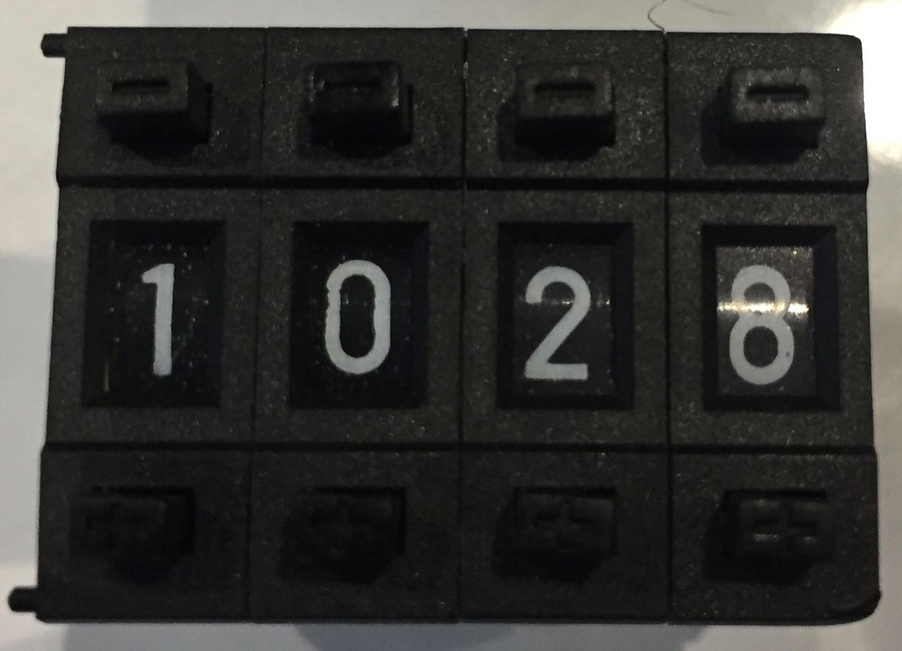
Having decided to limit the variables to two-digit integers, I looked around for some suitable input devices that would allow the programmer to set values for the variables and expressions. I ended up settling on using a 0-9 BCD (Binary Coded Decimal) thumbwheel as shown below. The thumbwheel switch lets you select any digit from 0 to 9 and outputs a BCD value, which takes up four bits per digit. Two of these digits could be combined to allow numbers from 0 to 99 to be entered quickly and easily.
![]()
A value module could have sockets for two digits, which could be read by the Arduino to get the current value. As each digit is from 0 to 9, but a single digit requires four binary digits to represent it, there are six values (10 to 15) which are unused. I realised I could use these extra values to specify variables - I only need four variables for now, so Blue could be represented by a digit value of 10, Red could be 11, etc. Two 4-bit digits would require 8 GPIO pins to read, which should be available on our program blocks.
To implement an expression however, I would need more than this. An expression would take the form of <number or variable> <operator> <number or variable>. For example:
Yellow + 5
Or:
15 * Blue
The operator of an expression must support at least the four basic arithmetic operations: plus, minus, multiply and divide. Other operators might be needed, especially for comparisons in an IF/THEN block. For comparisons we might need equals, less than, greater than and maybe some others.
A simple expression with two operands and one operator would therefore require 8 bits per operand and let's say 4 bits for the operator. We simply don't have enough GPIO pins on the Arduino to read all these bits, so I chose to use the PCF8574 and PCF8575 IO expander ICs to give more available inputs. The IO expander ICs use I2C to communicate with the Arduino, which drops our GPIO requirement down to two pins for the I2C protocol.
My initial value prototype fit nicely on a half-length breadboard and seemed to work well.
![]()
I initially implemented the expression module with two PCF8574 ICs, although a single PCF8575 could have done the job. The operator for the prototype simply used two pins from the Arduino, allowing four different operators. (I reasoned that a variable assignment would only use +, -, *, / while an IF/THEN would translate the four values as ==, <, and >.)
The expression prototype comfortably fit on a de-railed breadboard:
![]()
This example of an expression is equivalent to the code:
red = yellow / 21
I revisited some of these design decisions when I created the PCBs, but the principle has survived mostly intact.
Next up I will briefly (ha!) describe how I implemented the language in code.
Any questions or comments are more than welcome. 8^)
-
PCBs are here!
01/24/2019 at 01:57 • 3 commentsMy first JLCPCB order arrived yesterday - I am so excited! 8^)
I will be soldering some of these up later today...
![]()
![]()
![]()
I also have a pogo-pin programmer so I can re-program the Arduino Minis in place without needing the 6-pin headers soldered on. (I messed up with the placement of the screw holes here, but I can work around that...)
![]()
... and the "Universal Block" module works perfectly! 8^) (I will upload a demo video in the next day or two.)
![]()
-
PCBs Ordered!
01/16/2019 at 08:56 • 0 commentsThis is quite exciting! I have just submitted the order for my first batch of PCBs for this project! Four separate boards plus a bunch of components. I can't wait to get these and start building some (soldered) prototypes. 8^)
-
Implementing bi-directional comms part 2 - coding
01/14/2019 at 06:28 • 0 comments[My attention was briefly diverted by the arrival of some PCBs for this project, but I'll try to get the documentation back on track...]
In a previous log I detailed how the bi-directional communications will work: Blocks will listen for incoming data on both the hardware Serial port and a software (AltSoftSerial) port. 7-byte data packets have been defined, which should hold enough information for now, although the packet size may need to be increased, or ideally made variable length, in the future. When a packet is received, the destination is checked - if it is 0 (addressed to the current block) or 255 (broadcast) the packet is acted on and if not, the destination is decremented, the source is incremented (unless it is from the Master) and the message is sent on via the opposite port that it arrived on. (i.e. If the packet was received via the Serial port, it will be forwarded to the next node on the AltSoftSerial port.)
One minor issue with the protocol as defined: It uses a "BEGIN_TRANS" value, but that value could very well be a legitimate data value. I really need to come up with a better "start message" indicator, but I will leave that problem for another time... Suggestions for how to appropriately handle this are more than welcome!
So let's look at some code: (NB: I am not going to show all the code here, only parts that are different from the precious sample, or particularly interesting snippets.)
First of all, let's define some constants
// Some message constants
#define LEDS_OFF      0
#define RED_ON        1
#define GREEN_ON      2
#define WHO_IS_THERE  3
#define MODULE_ID     4

#define START_MSG     '#'

// Some address constants
#define MASTER_ID     254
#define BROADCAST_ID  255

// Set the number of bytes we need to read per message
#define MESSAGE_LENGTH  7
And we'll use a STRUCT for the message:
// A struct for the messages
struct Message {
  byte destination;
  byte source;
  byte messageType;
  byte data1 = 0;
  byte data2 = 0;
  byte data3 = 0;
  byte data4 = 0;
  bool recvInProgress = false;
  byte receivedBytes = 0;
};
The recvInProgress and receivedBytes fields are used when receiving a message via a serial port - it is not guaranteed that the entire message will be read at once, so some state needs to be kept to allow the messages to be received in several chunks.
Finally, declare a couple of variables to hold messages coming in on each port:
// Variables to hold the up and downstream messages...
Message upstreamMessage = Message();
Message downstreamMessage = Message();
For this sample, I am using a simple struct, but later on I will turn Message into a full class, but for now I'm keeping things simple-ish.
Now I should warn you, I tend to use pointers quite a bit in my code...
Sending a message is as simple as sending the START_MSG value, then each byte of the message struct:
void sendMessageOnPort(Stream* port, Message msg)
{
  port->write(START_MSG);

  port->write(msg.destination);
  port->write(msg.source);
  port->write(msg.messageType);
  port->write(msg.data1);
  port->write(msg.data2);
  port->write(msg.data3);
  port->write(msg.data4);
}
Because we are listening on two different ports, but the process is identical for each port, I created a function to listen on an arbitrary port:
bool checkForData(Stream* port, Message msg) {
  byte incomingByte;

  // If there is data waiting on the port, process it...
  while (port->available() > 0) {
    incomingByte = port->read();
    if (incomingByte == START_MSG) {
      // Initialise the message and start the receipt...
      // Note: if we are already receiving a message, but haven't received the full 7 bytes, we discard it.
      clearMessage(msg);
      msg.recvInProgress = true;
    } else if (msg.recvInProgress) {
      // We're receiving a message, stick this byte where it belongs...
      // incremented the bytes received
      msg.receivedBytes++;
      switch (msg.receivedBytes) {
        case 1:
          msg.destination = incomingByte;
          break;
        case 2:
          msg.source = incomingByte;
          break;
        case 3:
          msg.messageType = incomingByte;
          break;
        case 4:
          msg.data1 = incomingByte;
          break;
        case 5:
          msg.data2 = incomingByte;
          break;
        case 6:
          msg.data3 = incomingByte;
          break;
        case 7:
          msg.data4 = incomingByte;
          return true;
          break;
      }
    }
  }

  // If we get here, we haven't received a full message...
  return false;
}
The while loop here checks to see if there is any data on the nominated port, if there is, a single byte is read. If a message receive is not already in progress, the msg passed in is cleared with a helper function and the recvInProgress field is set to true. If a receive is in progress, the number of bytes received is incremented and the value read is placed in the appropriate field of the msg. If the byte received is the seventh byte of the message, the function returns true, otherwise the while loop checks again for any waiting data and does its thing all over if so...
Sometimes several bytes of data will be received into the Arduino's buffer while the code is doing something else, so several bytes may be read at a time. This function allows us to process the data as it comes in, and lets us read a few bytes go off and do something else while more data comes in, then read the next few bytes.
The main loop for the blocks is now:
void loop() {
  // Check for something coming from upstream (the direction of the MC)
  if (checkForData(&Serial, upstreamMessage)) {
    // we got a complete message from upstream!
    handleMessage(upstreamMessage, &Serial, &altSerial);
  }

  // Check for something coming from downstream (the direction away from the MC)
  if (checkForData(&altSerial, downstreamMessage)) {
    // we got a complete message from upstream!
    handleMessage(downstreamMessage, &altSerial, &Serial);
  }
}
We keep looping around, checking for data on the Serial port, then checking for data on the AltSoftSerial port. If a full message has been received on either port, the message is handled by a helper function. This function gets given the message, and it is told which port the message came in on (the first port parameter) and which port the message should be forwarded on if it is not for the current block.
A simple implementation of handleMessage might be:
void handleMessage(Message msg, Stream* inPort, Stream* outPort) {
  switch (msg.destination) {
    case BROADCAST_ID:
      // If the source is NOT the MC, increment the source for the next hop...
      if (msg.source != MASTER_ID) msg.source++;
      sendMessageOnPort(outPort, msg);
    case 0:
      // let's process the message...
      switch (msg.messageType) {
        case RED_ON:
        case GREEN_ON:
        case LEDS_OFF:
          showLED(msg.messageType);
          break;
        case WHO_IS_THERE:
          // Send my module id...
          Message reply = Message();
          reply.destination = msg.source;
          reply.source = 0;
          reply.messageType = MODULE_ID;
          reply.data1 = moduleID;
          sendMessageOnPort(inPort, reply);
          break;
      }
      break;
    default:
      // Increment the source and decrement the destination
      if (msg.source != MASTER_ID) msg.source++;
      msg.destination--;
      sendMessageOnPort(outPort, msg);
      break;
  }
}
Here, if the message is a broadcast message, it is first forwarded on to the next block and the execution of the switch is allowed to fall through to the next case, which is if the message is addressed to the current block. If the message is for the current block, the messageType field is checked and handled appropriately. In this case, the LEDs are turned on or off, or the block replies to the sender with its moduleID. (The module id of my blocks can be hardcoded, or set via jumpers, but that is a tale for another day...)
Woah! That is more code than I expected to include here - sorry about that. This code works fine, but it does have a couple of issues. There is no error checking or correction for starters. Some kind of CRC value may need to be included in the packet for this.
Secondly, the START_MSG sentinel value may appear as a legitimate data value in a message, so a better way of flagging the start of a message is needed. Why do we need a START_MSG indicator? Quite simply, not all the blocks in a chain will necessarily wake up at the same time. It is possible that a block may be slower to start up than the Master unit and it may miss the first byte(s) of a message. We need some reliable way of detecting when a message begins so that partial messages can be discarded. Maybe a string of bytes would be better instead of a single byte? I'm not sure how to approach this just yet...
Another issue is that not all message packets will need the full four data bytes, and some may even need to send more than four bytes of data. Variable length messages would be needed to solve this. A possible format would be destination, source, length, messageType, [data bytes]. I am not yet at the stage where I need more than four data bytes in a message, but I can see that day approaching, so I will definitely need to address the possibility of variable length messages sooner rather than later.
I'd be glad to hear other people's thoughts on these issues, or any other comments you may have on this project in general.
Next up I will start to describe the actual programming language and show how I have implemented it so far.
-
Implementing bi-directional comms
01/14/2019 at 03:44 • 0 commentsLast time I implemented a simple serial communications protocol, allowing the Master Controller (MC) to send commands to connected blocks. While this works well as it is, the MC has no idea which modules are connected, nor their topology. I need a way for the modules to identify themselves to the MC. The serial protocol as currently implemented only listens on one port and sends on the other - now I need to add the ability to reverse the direction on both ports. In order to do this, I need to add some more information to the data packets that are being sent.
At the moment, the data packet simply contains a destination address and a command value. While this worked for the blinky light demo, it really isn't good enough. At a minimum we need to know who sent the message, especially if the message is a request for identification or configuration data. So a source address byte needs to be included in the packet. Further, if the MC is querying the blocks, the blocks need to respond with their function. This could be done by using a special command code, but some blocks will also need to send extra information, such as their identifier and/or current value. For example, a variable block would need to convert not just that it is a variable, but which variable it represents and the value or expression that it contains. For now, I'll simply variable expressions to be a number (or variable), an operator (+, -, *, /) and another number or variable. So a variable block would need to send the MC up to four values - one for the variable identifier and up to three for an expression assignment.
With all the above in mind, I decided the data format should be:
Byte Value Description 1 Destination Address 0 == the current block, 254 == MC, 255 == Broadcast 2 Source Address Set to 0 when sending, this value is incremented with each hop 3 Command Command or response code 4 Parameter 1 Optional parameter 5 Parameter 2 Optional parameter 6 Parameter 3 Optional parameter 7 Parameter 4 Optional parameter In the last log I explained how the destination address is used in this protocol. The destination byte is effectively the number of hops a message needs to traverse before it reaches its destination. At each hop, the destination value is decremented, so when it reaches 0, the packet has reached its target. I use a similar approach for the source value but in reverse. At each hop, the source value is incremented, so when the packet reaches its destination, the source value will be the number of hops the message has traversed. Doing this will allow the MC to locate and identify blocks dynamically - simply send a "who are you?" message to all blocks and as each block responds, the source value of each packet will identify the position in the chain of the sending block.
Command values will be defined as needed. In the previous demo, the commands were LEDS_OFF (turn off the LED), RED_ON (turn the red LED on) and GREEN_ON (turn the green LED on). While being able to toggle the block's LED is great, we will need some more commands, the first two I will define are WHO_IS_THERE, which will ask all the connected blocks to identify themselves, and BLOCK_ID, which is the response a block sends along with one or more parameter values identifying the block and its configuration. The parameter values are optional and their use will vary depending on the command being sent. (To keep things simple for now, all data packets will include all seven bytes - a later enhancement to the protocol would be to include a data length in the packet.)
To make all this work, the main loop() will need to be modified. The demo code looped, waiting for incoming data on the hardware serial port and when it received a byte (the destination address), it looped waiting for a command byte and then acted on it. While this worked for the blinky lights demo, it is not really ideal and have several problems. For one, it is only listening for transmissions on one port, but we now need to listen for incoming data on both the hardware and software serial ports. Another problem is that it blocks while waiting for data after receiving the initial byte in a transmission - if data is coming in on both ports simultaneously this runs the risk of dropping data on one of the ports. Yet another issue if how do we really know where the start of a transmission is? What if a byte somehow gets lost in transit? Or if a block starts sending before the next block has fully booted?
To solve this last issue of where a transmission begins, a begin transmission value should probably be used. Then the loop could watch for a BEGIN_TRANS value on a port and start collecting the data. This should help keep message synchronised somewhat. As for the other issues, instead of grabbing an entire message at once, I use two variables to store an in progress message (one for upstream and one downstream) and as a byte is received on a serial port, the appropriate message is updated until it has been completely received. When the message is complete it can be acted upon. In the next project log I will start writing the code to implement this.