Amos
Amos-
Starting work on a simple serial protocol
12/18/2018 at 12:27 • 0 comments![]()
Having decided on serial communications for the blocks, I now need to devise a protocol so the blocks can communicate with each other and the master controller. What follows is some of the reasoning I used in devising the protocol I ended up using.
The Commodore 8-bit computers used a serial bus for their peripherals. Each device had two serial ports - the first device would be connected to the computer via one port, and the next device would be connected to the first via the first device's second port. Each subsequent device would be similarly connected to the previous device's second port, giving a long chain of connected disk drives and/or printers. Commodore's solution to identifying devices was to give each device a device id (sometimes set using DIP switches) which allowed for a small number of devices on the bus. (The address ranges used allowed for two printers, one (or two?) plotters, up to eight disk drives and a handful of other devices.) Hard-coding device ids won't work for a programming language (even with DIP switches) so I will need another way of identifying blocks, but the serial topology is a definite possibility.
One drawback with this design is that I need two serial ports and the Arduino Pro Mini only has one serial port available (on pins D0 and D1) so where to find an extra serial port? For that I turned to Paul Stoffregen's AltSoftSerial library. This allows you to add an extra software controlled serial port to your Arduino and should give me the extra port I need. On the upside, I would only need four wires connecting each block (power and ground and RX and TX) which would make for a neat layout.
![]()
The next thing I needed to do is determine some way of identifying blocks on the serial bus and for that I looked to the WS2812 LEDs. I discovered that you can purchase WS2811 ICs, which are the same as the chips in the WS2812 LED packages and I thought they might prove useful. For the longest time I tried to find a way to use the Worldsemi WS2811 IC to handle the serial communications, but I killed that idea as the WS2811 is designed for LEDs and only outputs three analog signals (one each for red, green and blue channels) where I needed a digital value. So I needed to come up with my own protocol.
Apart from the analog output, another problem with the WS2811 IC protocol is that to send a message to a specific device, you need to send data for every device in between you and the target. Each device in the chain gobbles up three bytes of data. To send a signal to the 10th device in the chain, you need to send 30 bytes of data (three bytes for each device). So while WS2812 LEDs are touted as individually addressable, they really aren't - you need to output the RGB values for every LED in the strip each time you want to change the colour of a single pixel. I wanted a truly individually addressable protocol...
My first, simplistic approach was to use relative addressing. Instead of assigning a unique id or address for each block, what if I used relative addressing? So instead of an absolute address, use the number of "hops" between you and the device you want to send the message to. To send a message to the next block, use an address of 0. The block after that is address 1, the one after that is 2 and so on. When receiving a message, each block will look at the destination address of the message and if the destination is 0, then it must be for you. If it is greater than 0, decrement the address and forward it on to the next block in the chain. There may be times when you need to send a broadcast message and blocks need some reliable way of communicating with the control unit, so why not use a coupe of special reserved addresses for this? 255 can be a broadcast id - if a block receives a message addressed to 255, then the block must act on that message and forward it without decrementing the address. Similarly, if the address is 254 it is for the control unit, so it is forwarded up the chain, again without decrementing the address.
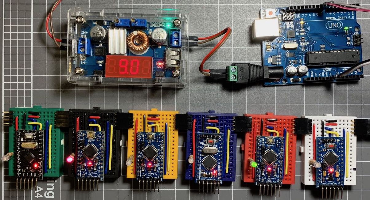
So I decided to see if I could get this relative addressing scheme working. I decided on the convention of connecting the hardware serial port (pins D0 and D1) to the "upstream" (i.e. going towards the control unit) and the AltSoftSerial port (pins D8 and D9) heading "downstream" (i.e. "away" from the control unit). For this initial test, I would only implement sending messages from the control unit "downstream" with no replies coming back from the blocks. Blocks will only forward messages (if required) downstream and not back towards the control unit. (For now.) I wired up some blocks (as seen above) with a red/green LED on pins A2 and A3, so I could toggle between red or green display. I decided that for now the message would be a single byte which would tell a block to either light the RED LED, the GREEN LED or to turn the LED off.
The initial setup code (identical for the control unit and the blocks):
#include <AltSoftSerial.h>

AltSoftSerial altSerial;

// Set some GPIO pins for LEDs
#define BICOLOUR_RED A2
#define BICOLOUR_GRN A3

// Some message constants
#define LEDS_OFF 0
#define RED_ON 1
#define GREEN_ON 2

#define BROADCAST_ID 255

void setup() {
  // put your setup code here, to run once:
  Serial.begin(9600);
  altSerial.begin(9600);
}
Sending a message is simple:
// Sends a numeric message over a number of hops (0 means the message is for the next in the chain)
void sendMessage(int hops, int mesg) {
  altSerial.write(hops);
  altSerial.write(mesg);
}
Note: This is a simple proof of concept, so I am not worrying about start or end message indicators and error checking? Who needs error checking? ;^)
For the blocks, the loop() is just waiting for a message on the Serial port, which it interprets as the first byte being the address and the second byte the message. If the message is addressed to block 0 or 255, the appropriate LED is lit, if not the message is forwarded.
void loop() {
  if (Serial.available()) {
    // read the incoming byte:
    int hops = Serial.read();

    // Wait for another bit of data...
    // Not really good practice, but let's roll with it for now...
    while (Serial.available() == 0) {}

    int msg = Serial.read();

    switch (hops) {
      case BROADCAST_ID:
        forwardMessage(hops, msg);
      case 0:
        switch (msg) {
          case RED_ON:
            digitalWrite(BICOLOUR_GRN, LOW);
            digitalWrite(BICOLOUR_RED, HIGH);
            break;
          case GREEN_ON:
            digitalWrite(BICOLOUR_RED, LOW);
            digitalWrite(BICOLOUR_GRN, HIGH);
            break;
          case LEDS_OFF:
          default:
            digitalWrite(BICOLOUR_RED, LOW);
            digitalWrite(BICOLOUR_GRN, LOW);
        }
        break;
      default:
        hops--;
        forwardMessage(hops, msg);
        break;
    }
  }
}
Note: Again, there is no error handling at all here and the code is far from production quality, but if it works I know I can continue down this path...
So with that code (or something very similar) loaded onto the blocks (Pro Minis) I decided to test it out. The control unit for this test was an Arduino Uno, and I set up a simple loop that told the blocks to flash their LEDs in a bit of a pattern like so:
  sendMessage(BROADCAST_ID, RED_ON);
  delay(500);

  sendMessage(BROADCAST_ID, GREEN_ON);
  delay(500);

  sendMessage(BROADCAST_ID, LEDS_OFF);
  delay(500);

  for (byte i = 0; i < NUM_BLOCKS ; i++)
  {
    sendMessage(i, RED_ON);
    delay(500);
    sendMessage(i, LEDS_OFF);
  }

  for (byte i = NUM_BLOCKS - 1; i > 0 ; i--)
  {
    sendMessage(i, RED_ON);
    delay(500);
    sendMessage(i, LEDS_OFF);
  }

  for (byte i = 0; i < NUM_BLOCKS; i++)
  {
    sendMessage(i, RED_ON);
    sendMessage(NUM_BLOCKS - i - 1, GREEN_ON);
    delay(500);
    sendMessage(i, LEDS_OFF);
    sendMessage(NUM_BLOCKS - i - 1, LEDS_OFF);
  }
  for (byte i = 0; i < NUM_BLOCKS; i++)
  {
    sendMessage(i, GREEN_ON);
    sendMessage(NUM_BLOCKS - i - 1, RED_ON);
    delay(500);
    sendMessage(i, LEDS_OFF);
    sendMessage(NUM_BLOCKS - i - 1, LEDS_OFF);
  }
Again, not pretty, but if it works, it works.
And the proof is in the pudding...
-
Initial design decisions
12/12/2018 at 12:12 • 0 commentsSo, I decided to create what I started to call a "physical block-based programming language" (I need a better name - any ideas?) and had tentatively selected the Arduino as the core of the project. A big factor in this decision was that I already had a handful of Arduinos (Nanos and Pro Minis) and they are relatively inexpensive - around $2USD for Pro Mini clones. My budget as a student could stretch that far at least. ;^)
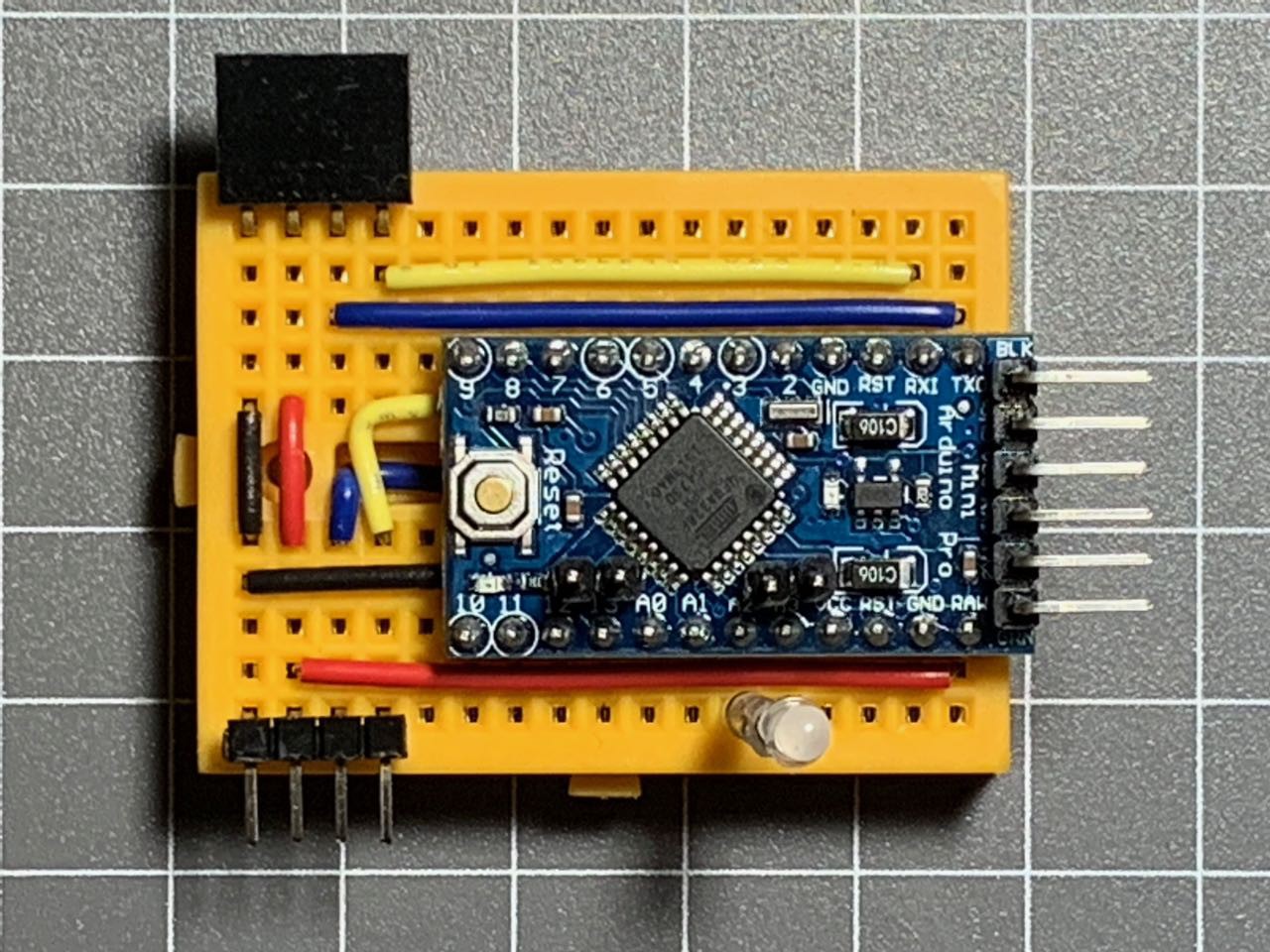
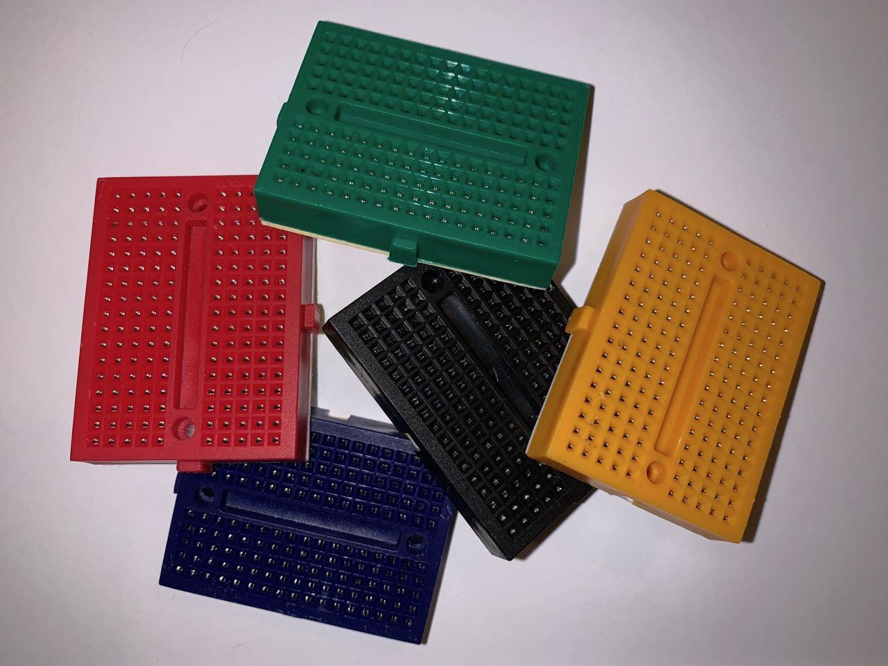
I had purchased some tiny breadboards in the past and I thought they might be useful for this project. The boards have 170 tie points (17 rows x 10 holes (2 lots of five)) and a Pro Mini fits nicely leaving 5 unused rows. Alternatively, 400 tie point boards could also be used if I need more space. I do like the look of the tiny boards though - the colours could be used to represent different programming constructs...
![]()
Picking the platform (Arduino) and the form factor (170 tp breadboard) was the easy part - now I need to work out how to connect the blocks/modules and get them to communicate. There needs to be some way for a control unit to query all the blocks/modules attached to it to determine their order and functions.
(Aside: I tend to use the terms block and module interchangeably with this project. I am still not quite clear myself if there is a distinction between the terms (in the scope of this project) and if so, why. I _think_ a block should represent a programming construct - a variable, IF, THEN, ELSE, output, etc. - and a module probably also includes things like expressions and any input or output devices. That seems to make sense and is how I will try to use the terms, but forgive me if I slip up and switch the terms around every now and then...)
I want(ed) to keep the blocks (and modules) as simple as possible and minimise the wiring, while maximising the flexibility of the designs. Each block should represent a single programming construct and should therefore know what thing it represents. (i.e. "I am a blue variable" or "I am a FOR loop".) The connections between the blocks needs to be standardised, no matter the function of the individual blocks. For example, I want to avoid having a FOR block requiring 6 input connections and a variable only needing 4 inputs.
My initial thoughts were I2C, SPI or serial connections. I2C was ruled out early on, as that would require each block getting a dedicated address (although I think I have a neat way of dynamically assigning I2C addresses that I want to try out) and I couldn't find an easy way to work out the order that the blocks were connected. SPI was also rejected early on, leaving serial as a likely possibility.
I grew up with Commodore computer (the Vic 20 followed by the Commodore 64) and these wondrous devices used a serial bus for their peripherals. Peripherals could be daisy-chained together, with each device having a pass-through port to connect the next in the chain. This seemed like a good fit, although with Commodore's serial bus, each device had a unique id used to address the device - I needed to allow blocks to be connected in an arbitrary configuration.
If I connect the blocks using a serial connection, I still needed a way to determine the order the devices were connected. For this I took inspiration from the WS2812 LEDs (aka NeoPixels) that are so popular. When using these LEDs, you can send a stream of data out and the first LED takes the first few bytes as its command and passes the remaining data through, the next LED takes the next few bytes and passes everything else on, and so on. The only problem with the WS2812 protocol is that it was unidirectional - data was sent by the microcontroller, but the LEDs did not send any response back upstream. I thought this scheme might be worth exploring if I could solve the unidirectionality...
(Note: While my proof of concept works, I am revisiting the whole process while documenting it here to see if there is anything I would do differently to improve the project. I already know some changes I want to make, but trying to document my thought processes might help me discover other changes I might want to include.)
-
Sneak Preview
12/10/2018 at 02:54 • 0 commentsHere is a short, un-narrated video of the proof of concept in action:
-
How it all started...
12/10/2018 at 02:52 • 0 commentsThis project started as a major project for the unit FIT3146 - Emergent Technologies at Monash University. I was studying this unit in semester 2, 2018 as part of my Bachelor of Information Technology degree. The unit was like one big hackerspace - we had a range of technologies to explore and play with, including eTextiles, Arduino, BBC Micro:Bit, virtual reality, LittleBits, Makey-Makey and Sphero. For our major project we were asked to "create an artefact - i.e. create something cool using the technologies and techniques we had explored in class.
While pondering what my final project could be, I was reminded of an idea I had in the early 90s, but never had the resources to realise at the time. Back then, I had wanted to create a learning tool, similar in principle to LittleBits, however focussed on logic blocks (AND, OR, NOT, XOR, etc) and discrete components. I even planned on creating "exploded" versions of common 4000 and 74xx series ICs, so you could see how they worked "under the hood". Unfortunately PCB fabrication was quite expensive and components cost a lot more than they do these days - I simply couldn't afford to put my ideas into practice.
Discussing the idea of a modular training tool with my lecturer and tutors, I had a flash of inspiration - what if I merged the concept of a modular toolkit with a block-based programming language like Scratch and created a physical programming language? (I would later discover that the term Tangible Computing described what I was proposing.)
Arduinos are almost a disposable commodity these days - less than $2USD for a Pro Mini clone. I did some initial planning and came up with the idea of a number of modules based around an Arduino, with each module representing a programming construct - a variable, an operation, a loop, a conditional (IF/THEN/ELSE), and output command, etc. These modules would be connected somehow (waves hands) and could be controlled by a "master controller". (I ended up using an Arduino Uno for the master controller, but did consider using a Raspberry Pi.) Once completed, you could plug the modules in to each other to create a program. Instead of using drag and drop on a computer screen, you would physically plug and play.
I might revisit my logic trainer idea one day - PCB fabrication is now super cheap and it would be a fun project, but for now I am committed to seeing how far I can push this tangible programming idea...