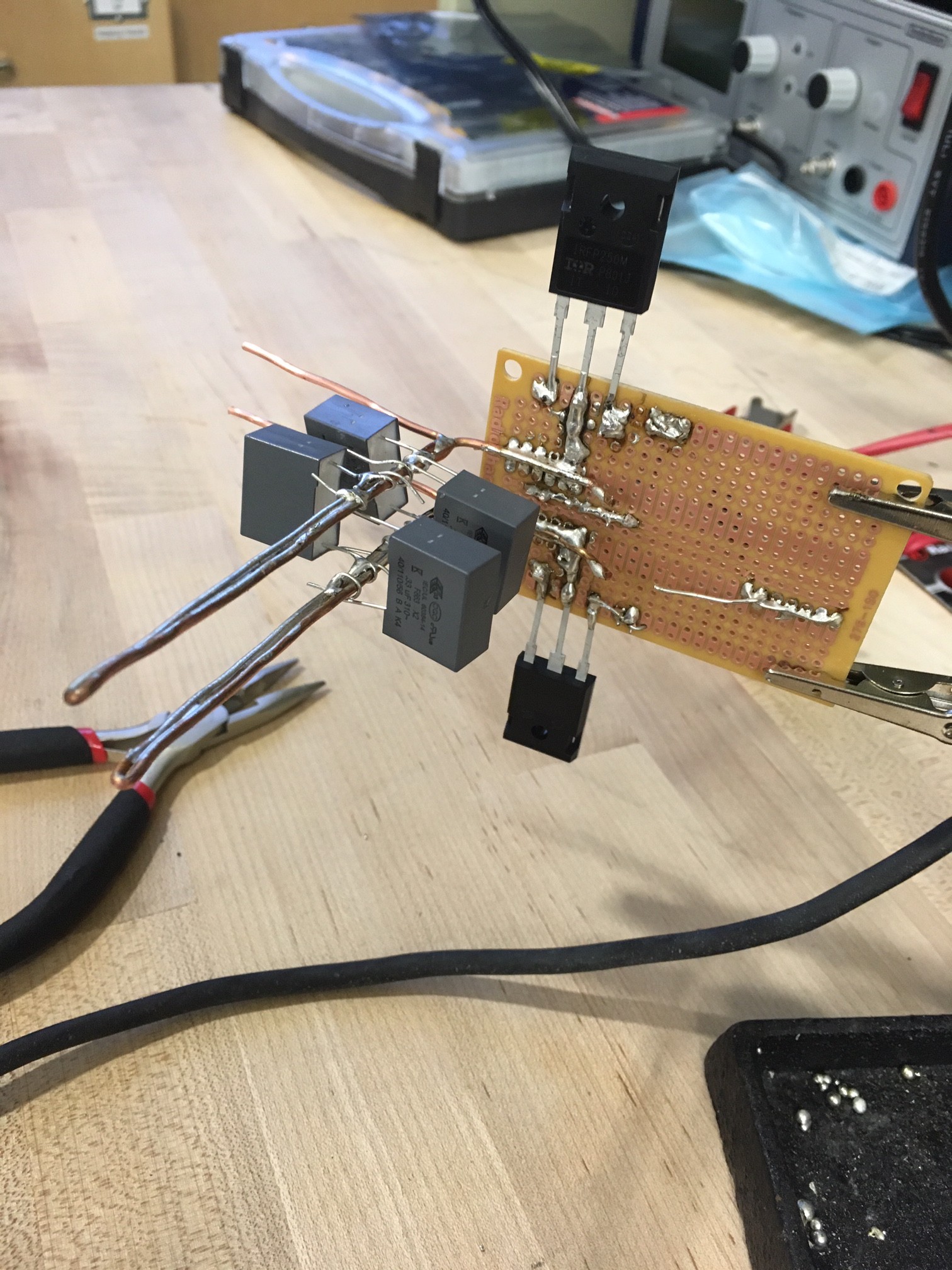
What got done:
- Soldered in fast diodes
- Disassembled premade choke assemblies to improve utility
- Bent and soldered in LC tank copper busbars (made from 14AWG solid copper wire), with connections available for work coil
- Soldered in 4 out of 6 initial capacitors for cap bank
- Sourced wire for work coil
Issues:
- Component side of board is crowded with crossed component leads; must monitor and inspect to avoid shorts
- Unconfirmed, but chokes may be wound with too thin of wire for the level of current they will be handling
Next steps:
- Solder on chokes and two more capacitors
- Form work coil and solder on
- Add power connectors
- Solder in power LED and its current-limiting resistor
- Test!
Current state of the board, with four capacitors soldered on capacitor bank:

 jdunbar360
Discussions
Become a Hackaday.io Member
Create an account to leave a comment. Already have an account? Log In.
Might be too late to add, but in high power circuits often there's a fuse component which acts as a safety switch, depending on the fuse's current ratings.
Are you sure? yes | no