Began to test heat dependance of current through PNP resistor on separate circuit, using a heat gun to safely increase the temperature of the base lead and using a micrometer to measure current. One transistor was fried, but we used a backup and repeatedly checked it to ensure that it was still functioning. Up through 300 degrees Celsius, we saw no leakage current through the transistor.
We later determined that this was because we were only heating the base lead of the transistor, rather than the head of the transistor itself. Once we began heating the head, we were able to source up to a mA of current (at around 220 degrees Celsius. We successfully used the PNP Transistor in the circuit to switch the relay on by the application of heat.
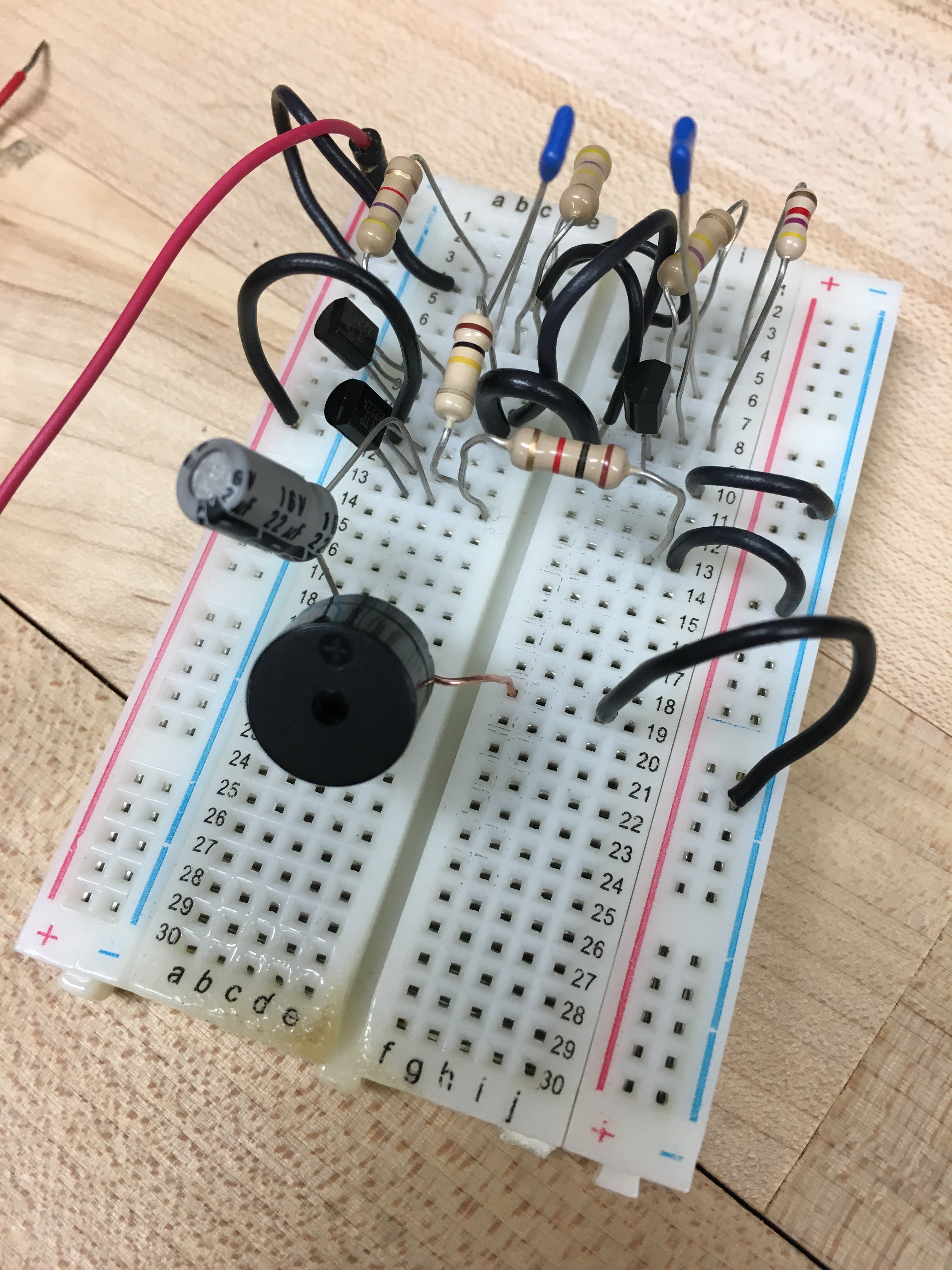
Next we tested the two audio transducers we have, and determined that one has a resonant frequency of about 1.8kHz, and the other has a resonant frequency of around 3.5kHz. Since we didn't have a power source that could produce an AC voltage at these frequencies, we built a small resonator circuit using 1 nF capacitors to generate a ~1.7 kHz frequency with the smaller transducer (see image). We plan to integrate this circuit into our final circuit board and use it to run the larger speaker when either half of the circuit switches the relay on--when either smoke or heat is detected.

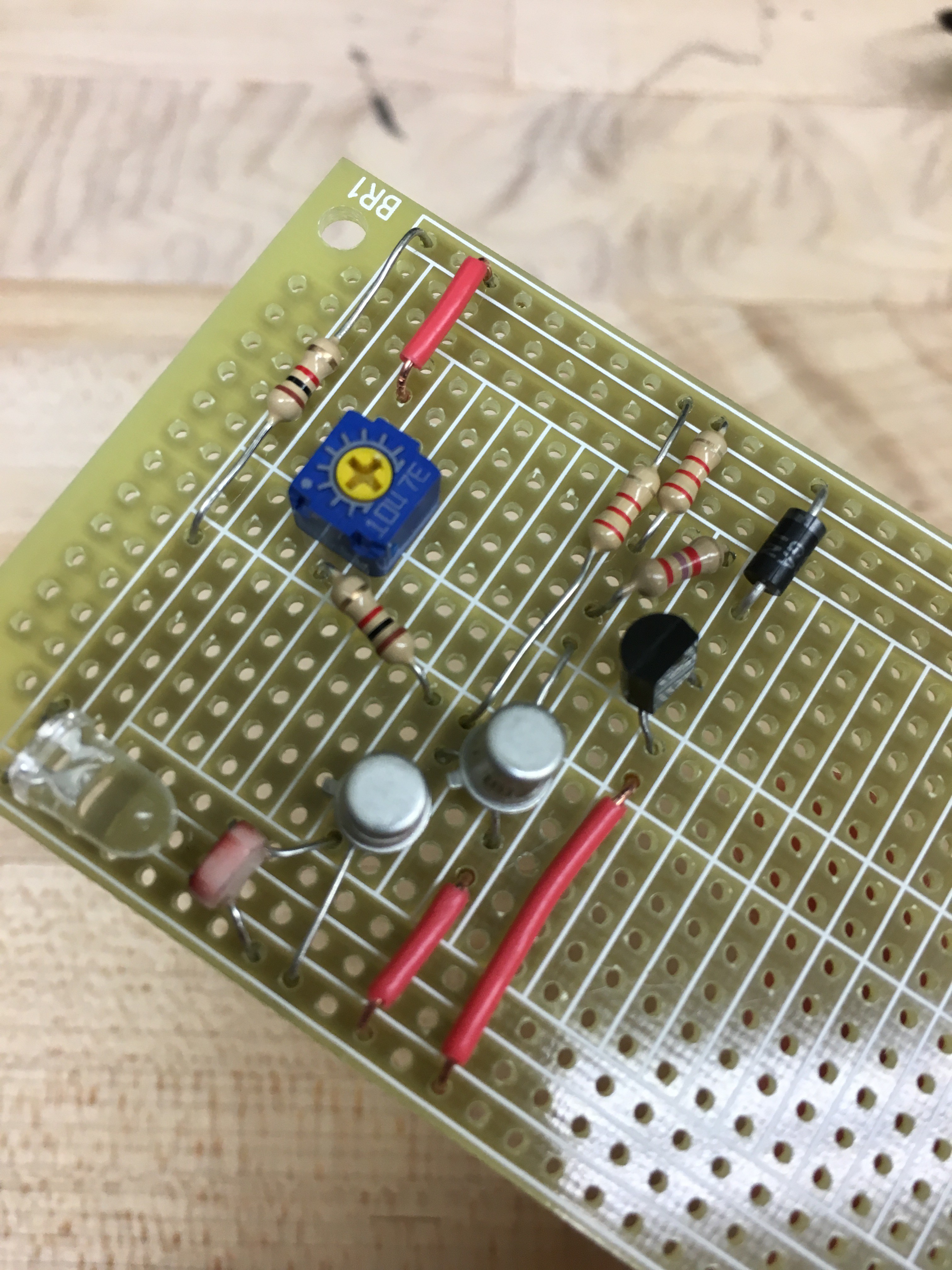
Finally, we began to solder the LDR section of the circuit onto the final breadboard. We finished all the components up until the SPDT relay (second image).

Discussions
Become a Hackaday.io Member
Create an account to leave a comment. Already have an account? Log In.