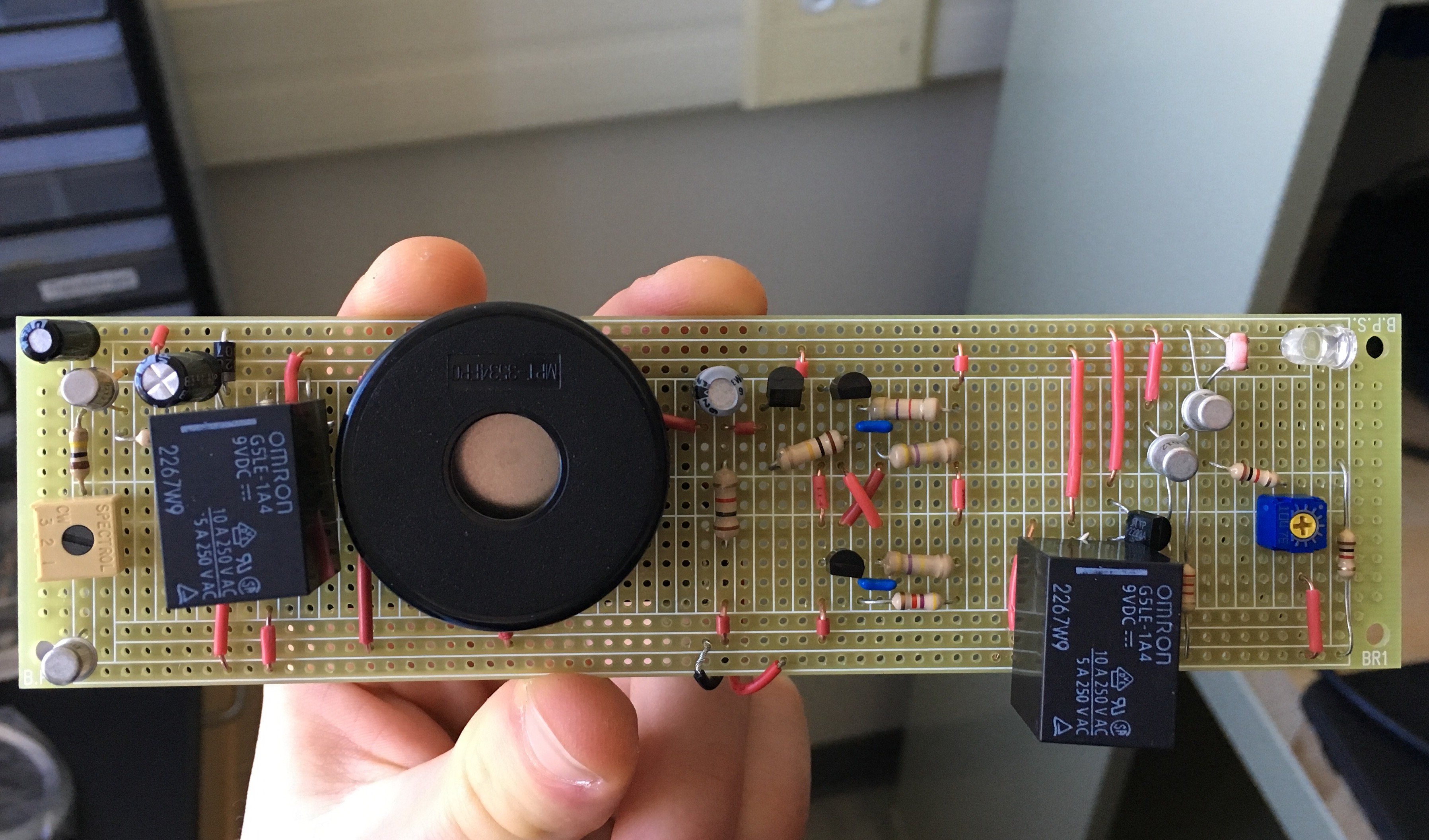
We continued to solder the third part of the circuit, which takes the 9V DC signal and converts it to a 1.7 kHz AC signal to feed into the transducer, onto the breadboard. Once we finished that, we wired up the transducer itself. We found that we had to create another ground line in order to ground the speaker. Finally, we glued a 9V battery socket onto the back of the breadboard and connected the power and ground leads to the power and ground lines on the top of the breadboard. (See image)

At this point, all the components of our project are in place, and so we're testing the various parts of the circuit again to verify that it is working correctly. Both methods of detecting fire are operating as designed; however, the speaker turns out to be much quieter when wired in parallel with the other two sections of the circuit.
Discussions
Become a Hackaday.io Member
Create an account to leave a comment. Already have an account? Log In.