Close
0%
0%

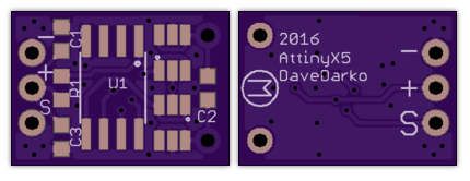
DC motor board with attiny13

finally soldered

Similar projects worth following
Help is highly appreciated.

Need common pitfalls and traps for young players, never really worked with a MOSFET before :D

Hand over tutorials.

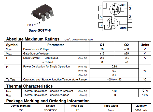
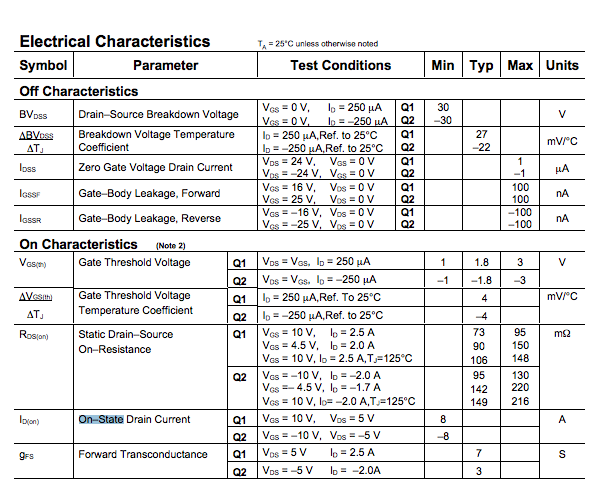
Does the MOSFET fdc6333c from fairchild I already bought make sense for this?

"Recently my dad made me buy some pwm to dc motor controllers (20EUR) for him, basically a servo motor setup but without the analog position and designed for a continuos motor mode. With that order I got me some attiny85s and some dual channel NP mosfets to start building something like that..."

- copied comment from myself on @Radomir Dopieralski s #Ensmarten Your Servos project.

Man I'm lazy.


Pricing Stuff

- I should (read: have to ) calculate this on every project

- 1.50 EUR per attiny85

- 2x 0.71 EUR for the MOSFETs

- some caps and resistors

- 1.50 EUR pcb yet to be designed but shouldn't be much more than

So around 5 Euros give or take. Sounds much better than 20 bugs. Software will be tricky though, but since it's hobby - it's free.

Fahrtregler.sch

sch - 344.66 kB - 10/22/2016 at 17:26

Download

Fahrtregler.brd

brd - 61.68 kB - 10/22/2016 at 17:26

Download

MOSFET.lbr

lbr - 11.56 kB - 10/22/2016 at 17:26

Download

View all 4 project logs

Enjoy this project?

Share

Discussions

agp.cooper wrote 10/22/2016 at 15:10 point

Hi,

I can't actually work out what you are trying to do!

A schematic of your board and a description of your project would help.

The MOSFETs will be fine for small motors that you are likely to be considering.

The rule with high powered MOSFETs is that both the upper and lower transistors are turned off before switching. You will see designs where each transistor is controlled by the MPU. Apparently (unlike Bipolar transistors) the transition current can kill them because the switching times are slow (and they can over-heat).

Probably not be a problem at your power level and with these devices as the gate capacitance is only 200 to 300 pF (pretty low) and switching time is in the order of 10 ns (pretty fast).

Depending on the motor and your power supply you may need to use PWM. So you will need to use the timers on the ATTiny85 (I hope you like reading the ATTiny85 datasheet) for PWM.

For the ATTiny85 I would suggest using a DigiSpark (at least to debug your project) as it can be used with the Arduino IDE (there are other ATTiny85 based produces like the DigiSpark you can use as well). You may have to hunt down libraries for the ATTiny85 unless you love to code!

Do some research on motor noise (electrical), it can make life difficult if precautions are not taken. Controlling motors with a MPU can be surprising hard (if you are unlucky).

AlanX

  Are you sure? yes | no

davedarko wrote 10/22/2016 at 17:24 point

Hey Alan, thanks for the input, I'm fine on the Attiny side I think, my main worries are with the mosfets. As you were saying the tiny85 is supported very well on the Arduino IDE for not leaving my comfort zone too much and I have accomplished some projects with the Attiny+Arduino already - my #USB cable tester would be the most "complex" one.

I'm going to upload the schematics now and post some screeners of EAGLE.

  Are you sure? yes | no

davedarko wrote 10/22/2016 at 17:28 point

btw. there's also a (quite long) discussion on the resources log. 

I've updated the picture and file sections.

  Are you sure? yes | no

agp.cooper wrote 10/23/2016 at 02:21 point

Hi Dave,

I can see from your USB cable tester that this project is "child's play" for you!

-

Another question for you is how do you intent to monitor your motor current or is it set the PWM duty and forget?

With regard to PWM frequency, if you don't mind the audio noise (~500 Hz) there is nothing stopping you from using analog out for this application.

And do you intent to control the motor speed?

-

Looking at your schematic I would make the following suggestions or comments.

Back EMF:

C1 & C3 may need a bulk capacitor (100uF?) across Vcc as well to absorb back EMF from the motor. C2 is usually for RF suppression only.

The motor capacitor (C2) is best on the motor rather than on the board but no harm having both.

*** I assume you are going to use a battery with no regulator for Vcc! ***

If you try and use a regulator (such as on the DigiSpark) and the peak motor current draw is more than say *** 1 Amp *** then likely you will DIE!   

If you insist on using a regulator then make sure it is able to handle the peak (loaded starting) current, add a 100uF or more bulking capacitor to Vcc, and a power diode from Vcc back to the battery. The Vcc line will still be noisy but at least it will not take out the ATTiny85!

At the end of the day, you may need to use a separate motor and MPU power supplies.

Switching MOSFETs:

I would have a pull down resistors on the MOSFET inputs in case the connections come loose or the software is buggy. I am not worried about having "dead-time" for these MOSFETS.

Inductive EMF:

If the motor leads are long then twist them to reduce the inductive currents. Inductive currents may upset your inputs.

Regards AlanX

  Are you sure? yes | no

K.C. Lee wrote 10/22/2016 at 17:40 point

Easy way is to drive the individual MOSFET - i.e. using 4 I/O lines so that delays can be controlled in the firmware for the transition to prevent cross conduction.  This also reduces the capacitive loads by factor of 2.

  Are you sure? yes | no

Eric Hertz wrote 10/22/2016 at 18:05 point

At that level I imagine you'd have to work at the register-level rather than the arduino-library-level, but the Tiny85 has two PWM channels *and* complimentary-outputs for each channel, *with* dead-time generators for exactly the purpose you've described.

  Are you sure? yes | no

Alex wrote 10/22/2016 at 20:36 point

This Timer1 looks perfect for this use case. Quite powerful timer on such a small controller.

  Are you sure? yes | no

K.C. Lee wrote 10/22/2016 at 21:21 point

You would only need to use 1 pair of complementary PWM for speed control.  The other H bridge control lines for changing direction are static.

Now that I think about it a bit more.  Forward looks like this and reverse is simply turning on Q3/Q2.


So to control speed, you only need to control the duty cycle of Q4 for forward and Q2 for reverse.

If you have Q1/Q3 or Q2/Q4 pairs turned on, you have dynamic braking.

If you want to get fancy, you can do regenerative braking by playing with the duty cycle and alternating between upper/lower MOSFET of H bridge in PWM.

http://www.modularcircuits.com/blog/articles/h-bridge-secrets/h-bridges-the-basics/

  Are you sure? yes | no

Similar Projects

Does this project spark your interest?

Become a member to follow this project and never miss any updates