-
Capturing the Data - Part 2
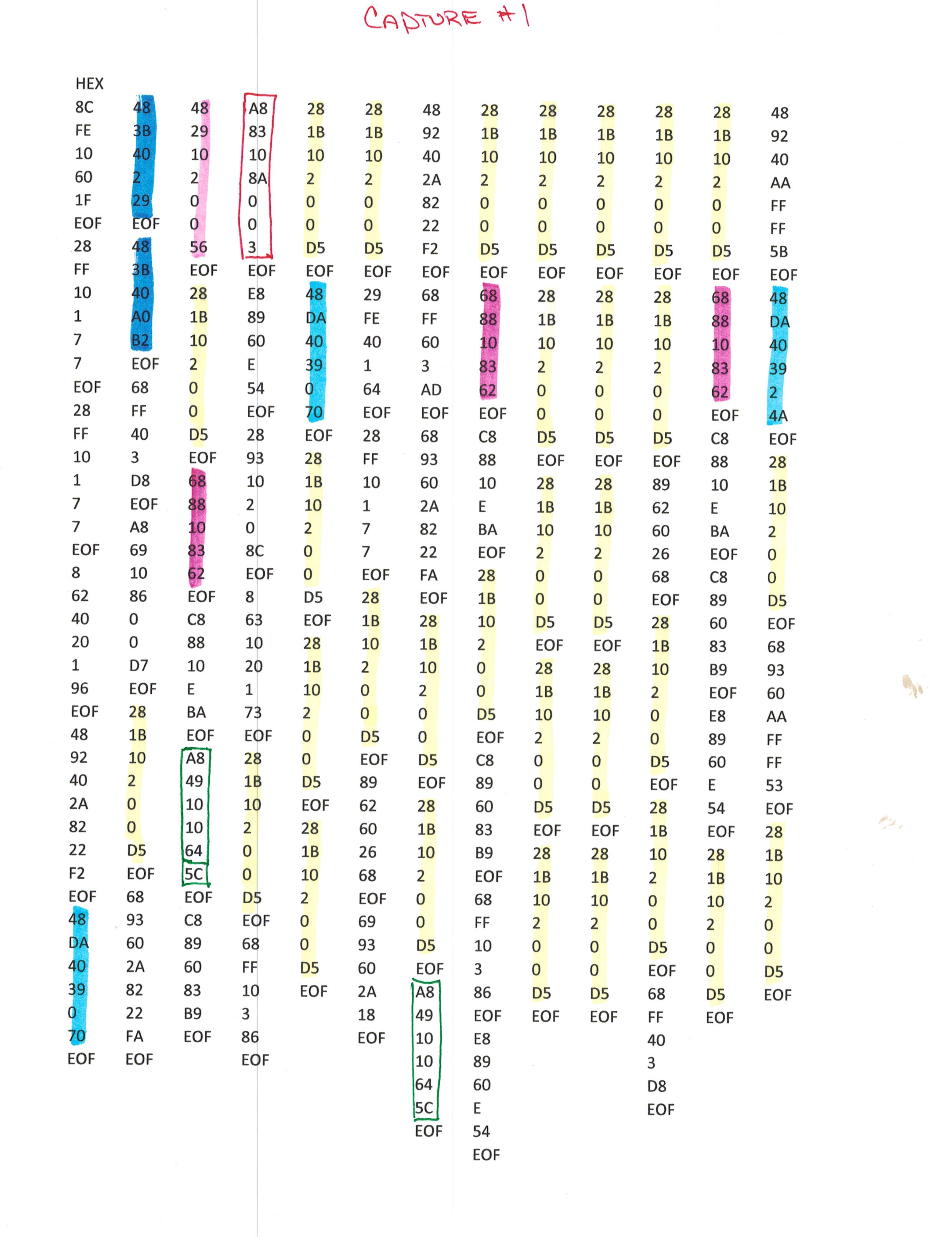
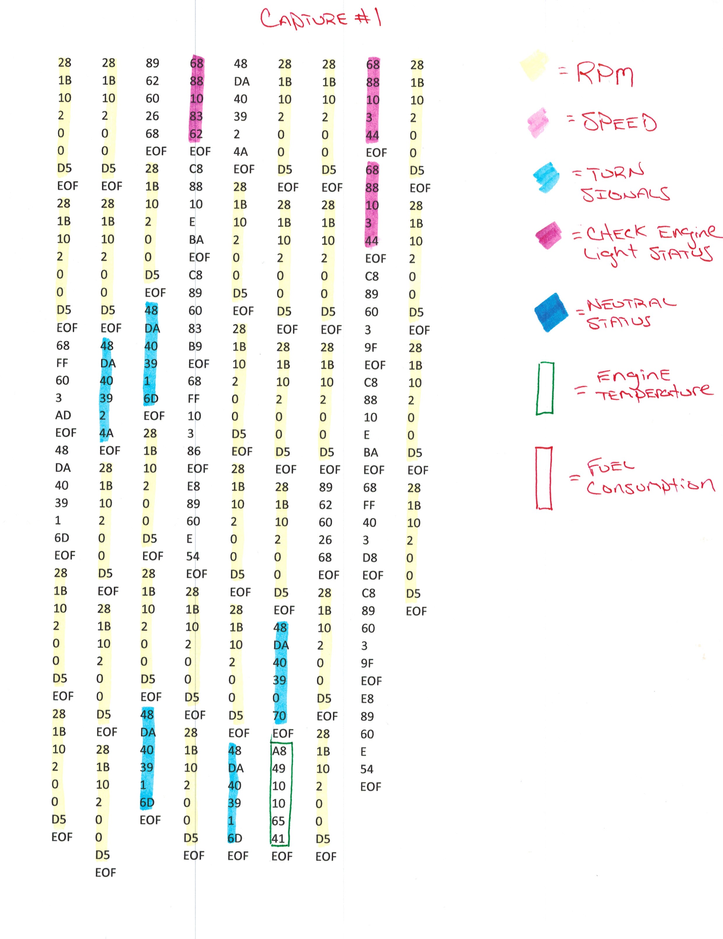
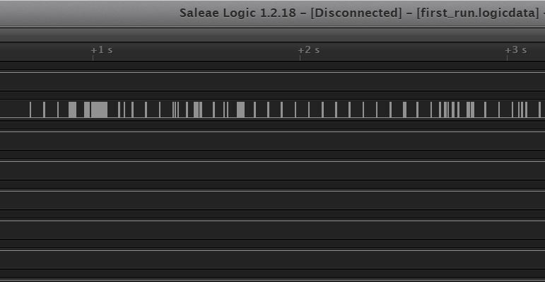
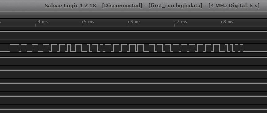
12/21/2018 at 11:57 • 0 commentsRather than writing code to read the data bus in arduino and then porting the code to Atmel Studio for use on another microprocessor, I've managed to capture the J1850 VPW data and decode it using my Saleae Logic Analyzer and Microsoft Excel. As a test, I captured 5 seconds of data using my logic analyzer shown below.
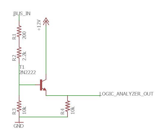
To interface the 5v logic analyzer with a signal from the data bus that had a high of 7v, I used an emitter follower, and took advantage of the fact that the output on the emitter follower would be a diode drop lower than the input on the base of the transistor. I used the below schematic to read the bus using the logic analyzer.
The +12v was connected to the motorcycle's +12 on the J1850 connector. The grounds between the motorcycle and the logic analyzer were connected together.
After I captured the data on my $10 logic analyzer, I exported to CSV, selecting "between the specified times" in the "samples to export" dialogue box. This way it only exported the change in state and timings rather than every sample that was collected.
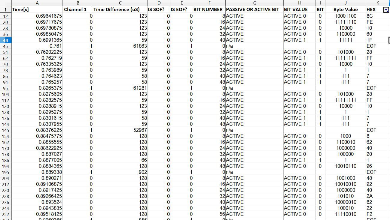
I opened the csv and created formulas within excel that would take the timings, determine if they were active or passive 1's or 0's, then combine every 8 bits within a frame, and finally convert the binary to hex.
SOF and EOF are Start of Frame and End of Frame, respectively. I've begun to decode some of the data, but there is extremely little documentation, and no official documentation on what the codes stand for and mean. This could take a while...
![]()
![]()
-
Capturing data from the bus
12/18/2018 at 11:52 • 0 comments![]()
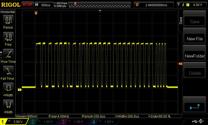
The first step in this project was to scope the signal on the data bus, which uses J1850 VPW, to verify I had the right source for the data, verify the voltage, and verify the signal itself. I had a few automotive 3-pin connectors lying around, so I spliced in a connector on the ECM tuning cable. The connector was 4-pin, but only 3 pins were used: GND, +12v, and Data.
In the above image you can see one transmission that was captured on the data bus. The high signal was 7 volts, as it should be.
![]()
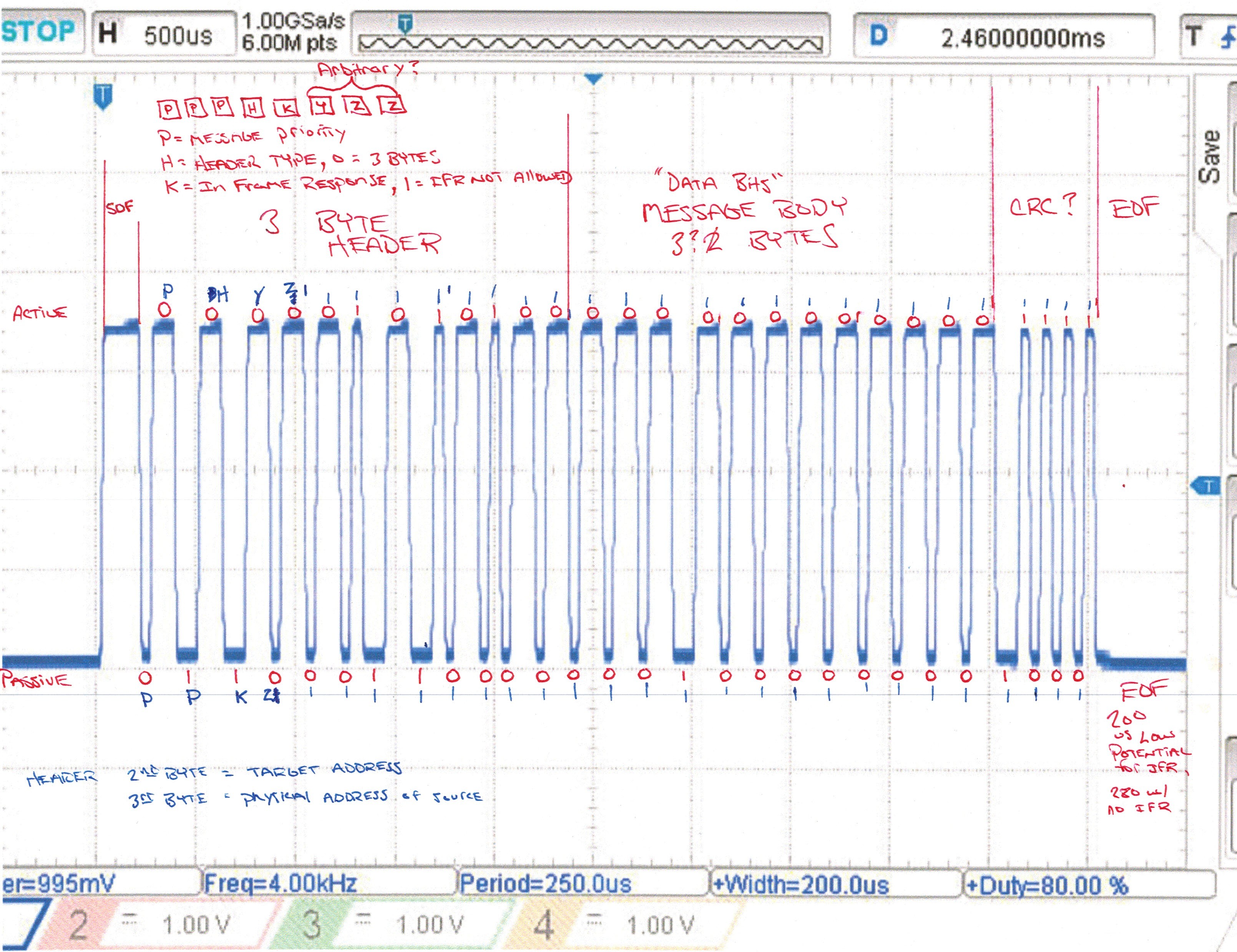
Inverting and printing the image, I was able to decode the signal, which was transmitted as a total of 7 bytes. The header was 3 bytes, the message was another 3 bytes, and there was 1 byte for CRC (cyclic redundancy check) which I have yet to figure out if I want to verify the integrity of the message received.
The next step in the project will be to create some code to automatically capture and decode this data, then send it via serial com (most likely using an Arduino for simplicity) so I can see the HEX values of the data that was sent.
The above binary:
00101000
00011011
00010000
00000010
00000000
00000000
11010101Translated to:
0x28
0x1B
0x10
0x2
0x0
0x0
0xD5The above is an RPM message sent from the ECM while the bike was off. I'm trying to find a good resource for the captured data, to determine what messages are what. So far I've found 1 example online of someone doing a similar project, http://momex.cat/en/HD-tacho-part1, and there is also a nice reference to the data on Github at https://github.com/stelian42/HarleyDroid/blob/master/README which shows the following data and its meaning:
        28 1b 10 02 xx xx : rpm, xxxx = rotations/minute * 4
    48 29 10 02 xx xx : speed, xxxx = km/h * 128
    48 3b 40 xx       : gear in neutral if (xx & 0x20),
                      : clutch engaged if (xx & 0x80)
    48 da 40 39 xx    : turn signals, xx = 1,2,3 for left/right/both
    68 88 10 03       : check engine indicator off
    68 88 10 83       : check engine indicator on
    a8 3b 10 03 xx    : current gear, xx = 1,3,7,15,31,63 for gears 1-6
    a8 49 10 10 xx    : engine temperature, xx = degrees Fahrenheit
    a8 69 10 06 xx xx : odometer, xxxx = ticks, each tick = 0.4 meters
    a8 69 10 86 xx xx : same as above, but a wraparound occured
    a8 83 10 0a xx xx : fuel consumption, xxxx = ticks, each tick = 0.000040 liters
    a8 83 10 8a xx xx : same as above, but a wraparound occured
    a8 83 61 12 dx    : fuel gauge, x = level (0-15)
Harley Davidson J1850 Visual Display Interface
Creating a visual display interface that communicates data captured from a motorcycle's data bus.
 George Gardner
 SOF and EOF are Start of Frame and End of Frame, respectively. I've begun to decode some of the data, but there is extremely little documentation, and no official documentation on what the codes stand for and mean. This could take a while...