Ben Peters
-
Final Tests 25.04.2019 - Project Completion
04/28/2019 at 09:32 • 1 comment![]()
Please follow this link to see the final testing videos. The project is finished now and I will upload all resources needed to build the prototypes very soon. The thesis will be uploaded for those who are interested the academic side of the project or want to see the project conclusions in more detail.
-
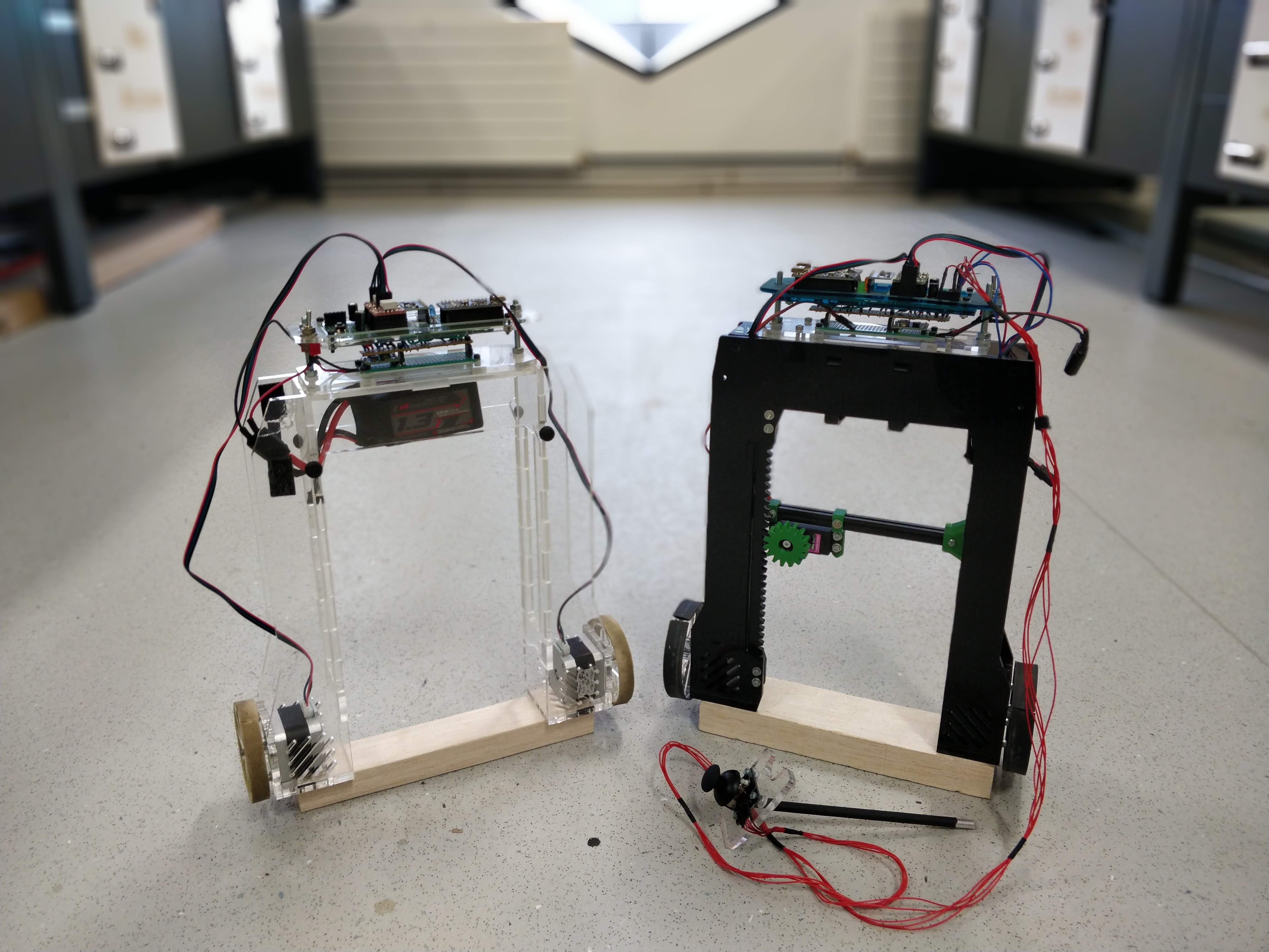
2nd Prototype Working Backpost 05.04.2019
04/18/2019 at 08:35 • 0 commentsI'm backposting here because I have been busy on my write up. I thought I should share the videos of the first tests of the 2nd Prototype on the day I managed to get the whole thing working. See this link for the google photos shared folder.
![]()
-
Final Designs for Prototype 1 and Prototype 2
04/18/2019 at 08:17 • 0 commentsI have taken a break from updating this log due to the looming thesis deadline (29th April). I have finished the design work for my project so I thought I would share renders so you can understand the two prototypes I designed and built on this project more clearly.
Prototype 1 final CAD render:
![]()
Prototype 2 final CAD render:
![]()
-
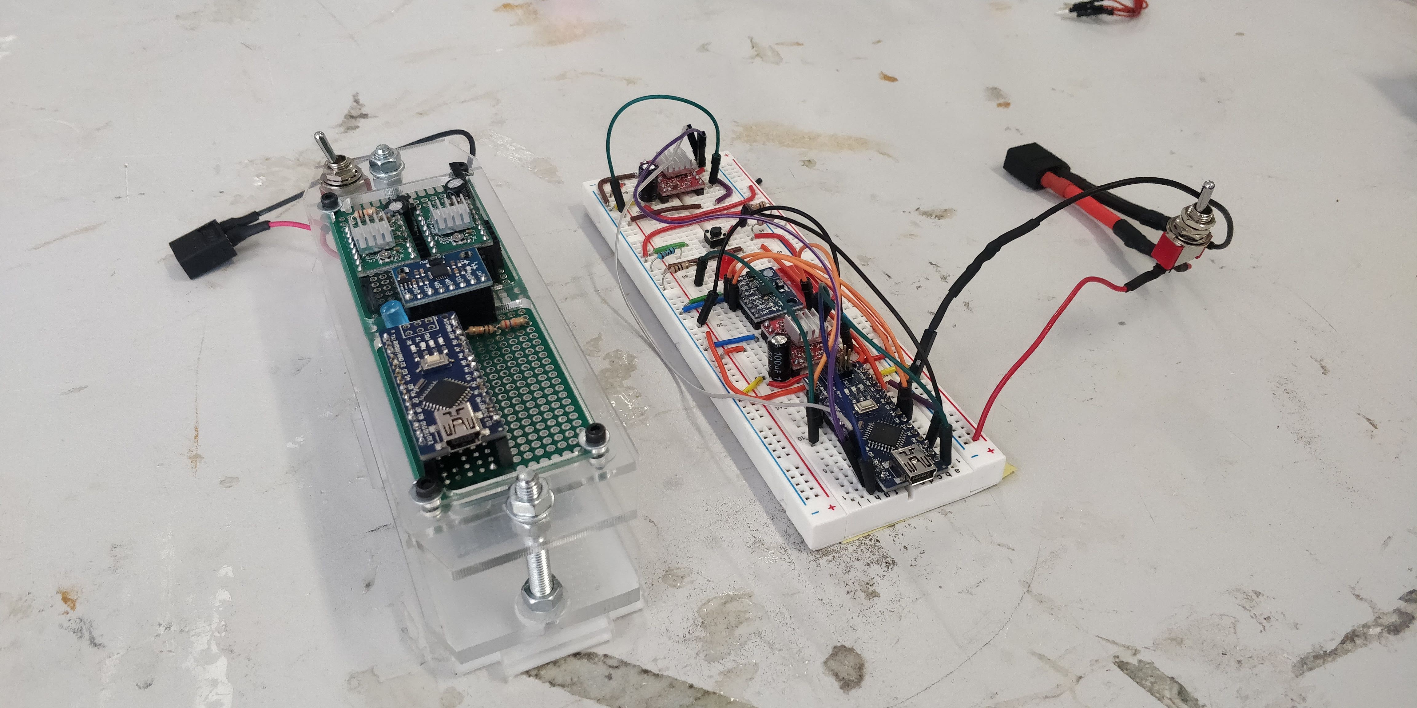
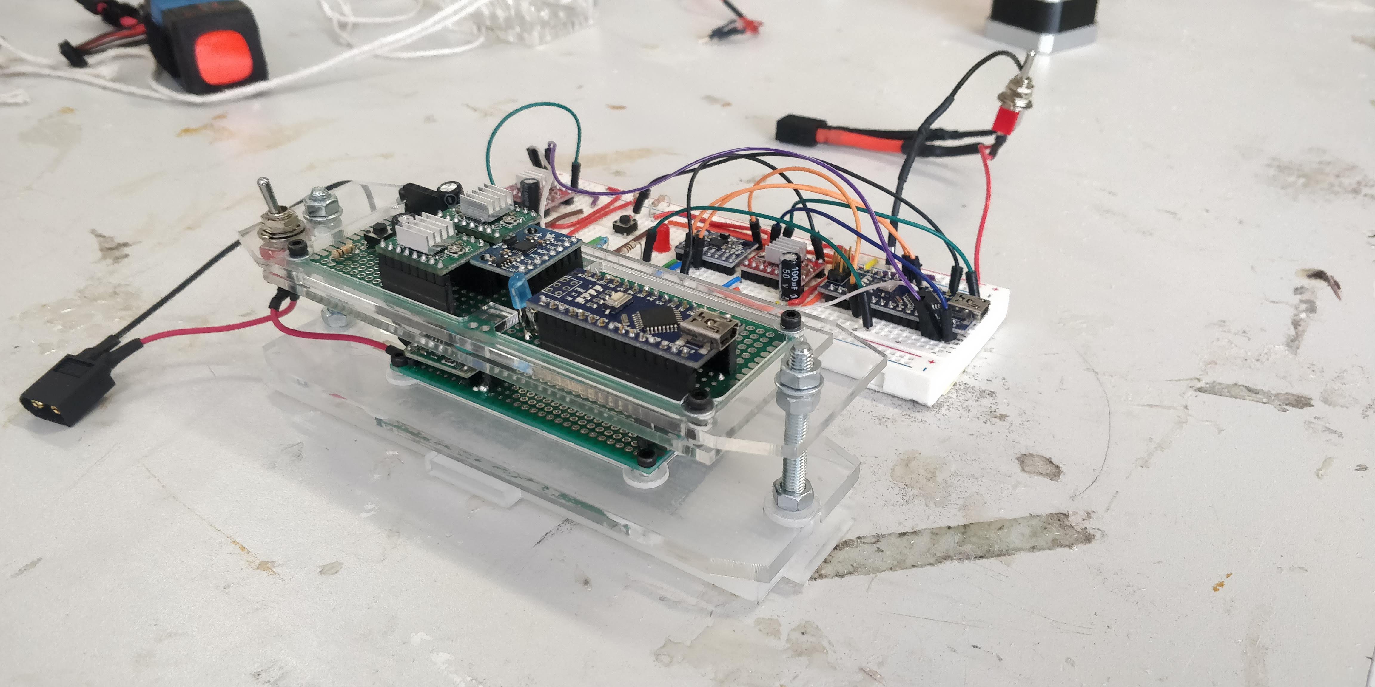
Building the Brain of Prototype 1 01.04.2019
04/01/2019 at 14:23 • 0 commentsSince last time, when I posted that I had completed the Prototype 2 chassis and crane design, I have been working on designing a robust soldered circuit to replace the breadboard (and all the trouble with shorting etc. it has brought). I have some nice time-lapses of the soldering and construction; once they have uploaded to my google photos I will post a link.
![]()
![]()
Breadboard and solered arrangement side by side... quite an improvement right? Circuit diagrams will be uploaded in due course. -
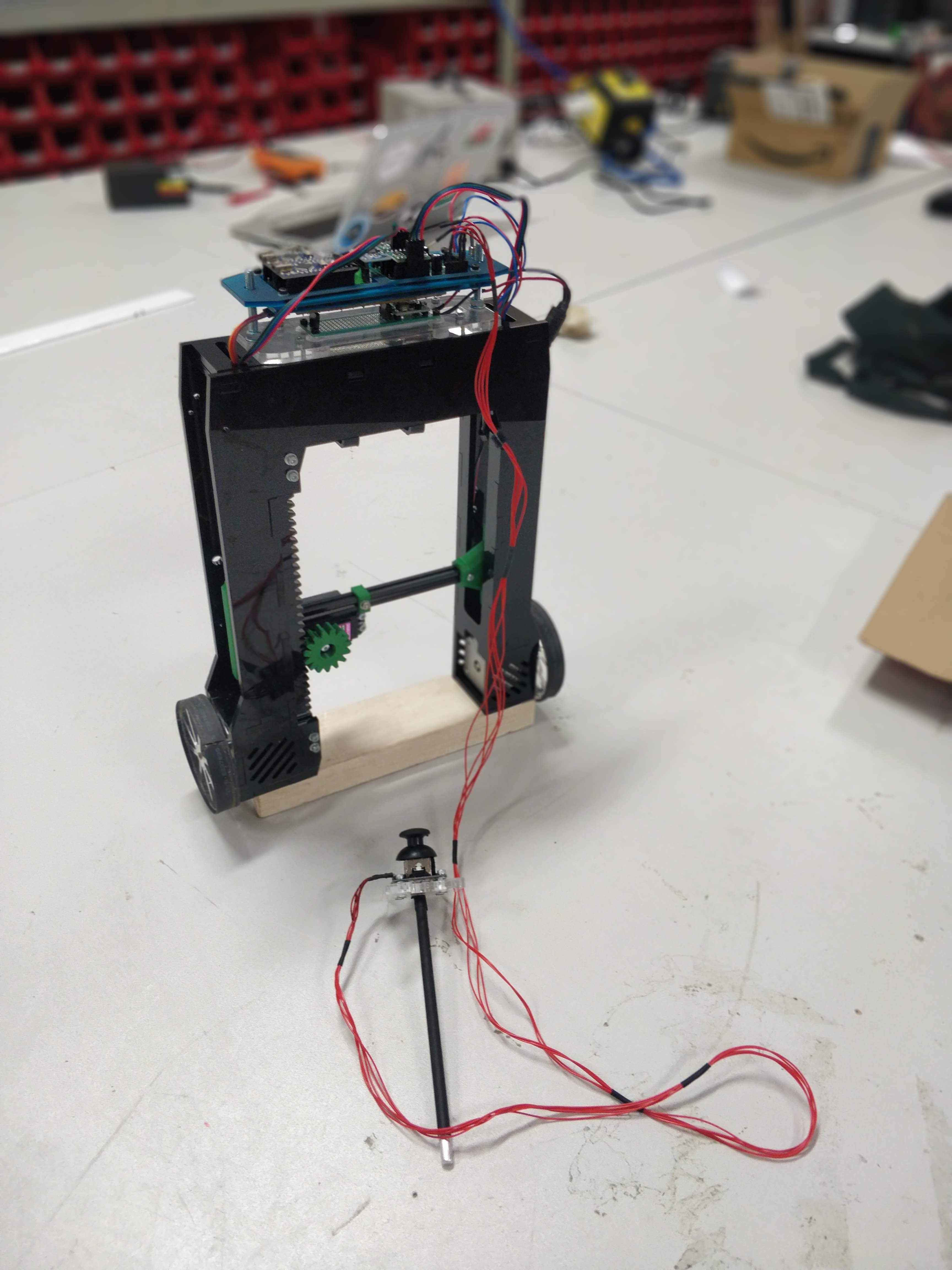
2nd Prototype Chassis Designed and Built 24.03.2019
03/24/2019 at 15:02 • 0 commentsWith the completion of the sliding mechanism, it was time to build the entire prototype 2 chassis.
The aim of this prototype was to integrate a crane boom into the chassis.
The secondary improvements based on critisims of the first prototype were:
- Clips to secure battery and reduce swinging about
- Wires from stepper to be easily routed
- Power switch to be connected to the robot frame rather than floating
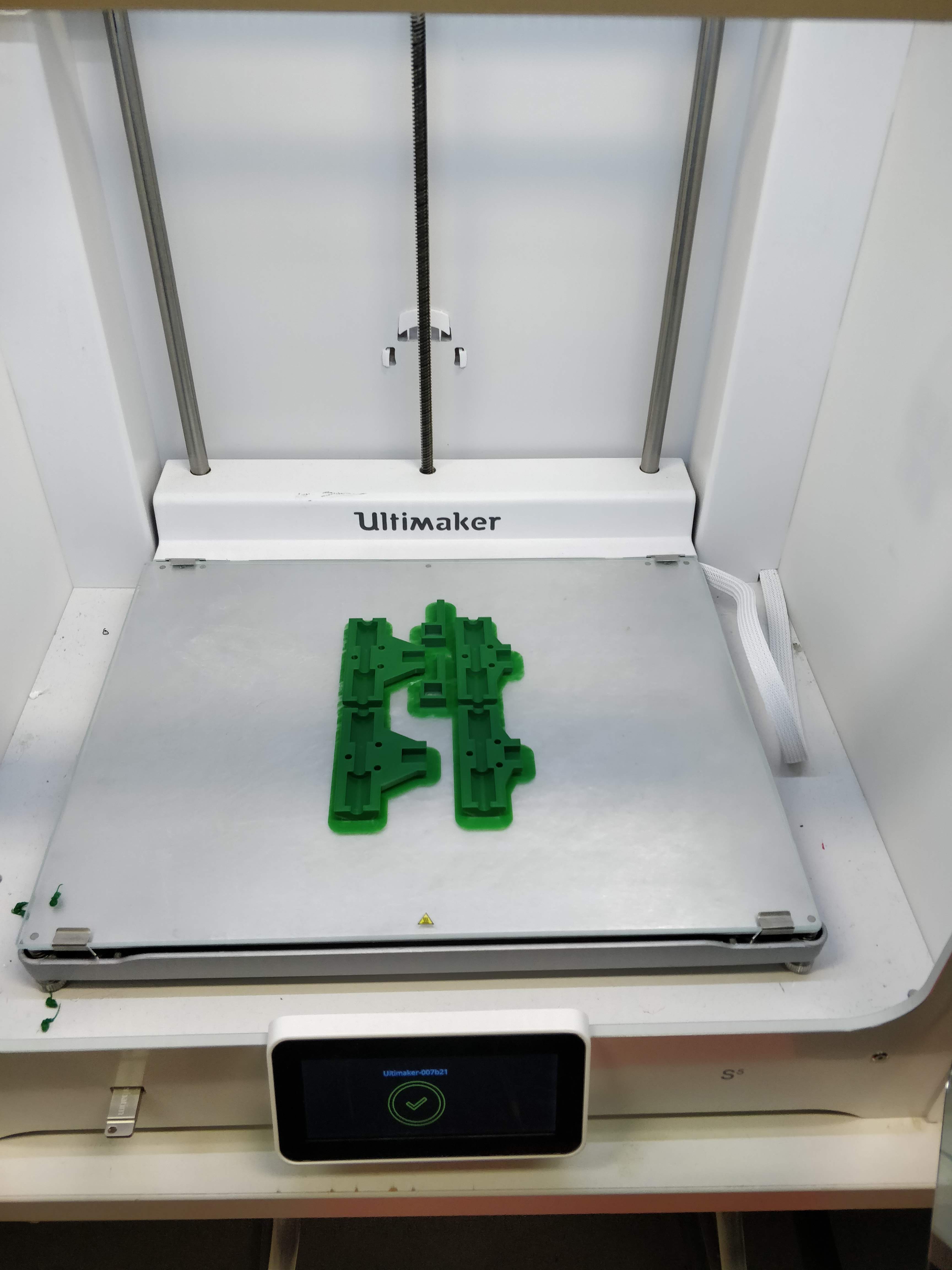
After many late nights, the picture below shows the completed result.
![]()
![]()
![]()
Please see the link to a video of the operational crane mechanism!! LINK
My main goal now is to integrate this with the self balancing capability of the first prototype. I also intend to move from a breadboard to a soldered stripboard because this has been causing me many issues.
-
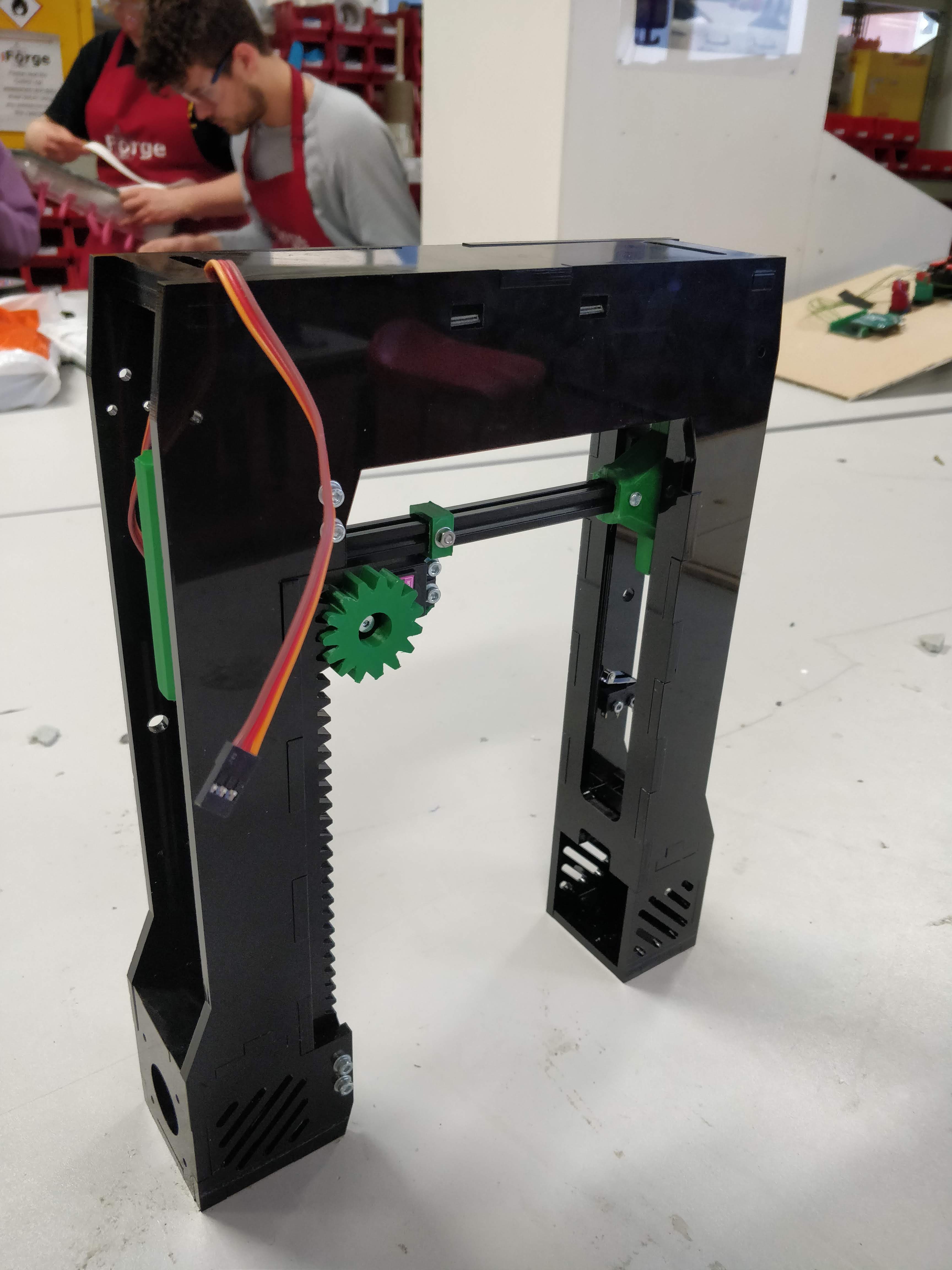
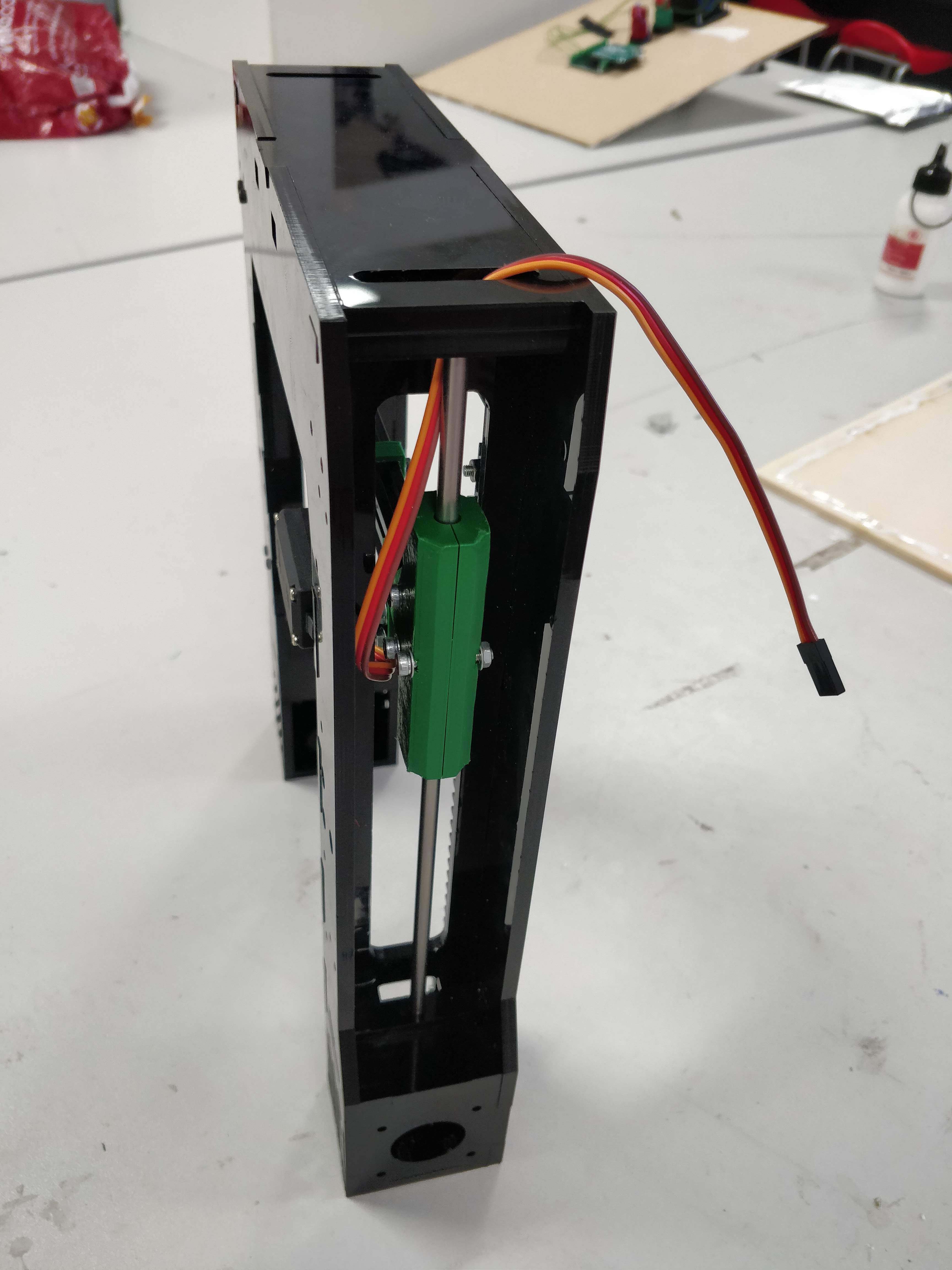
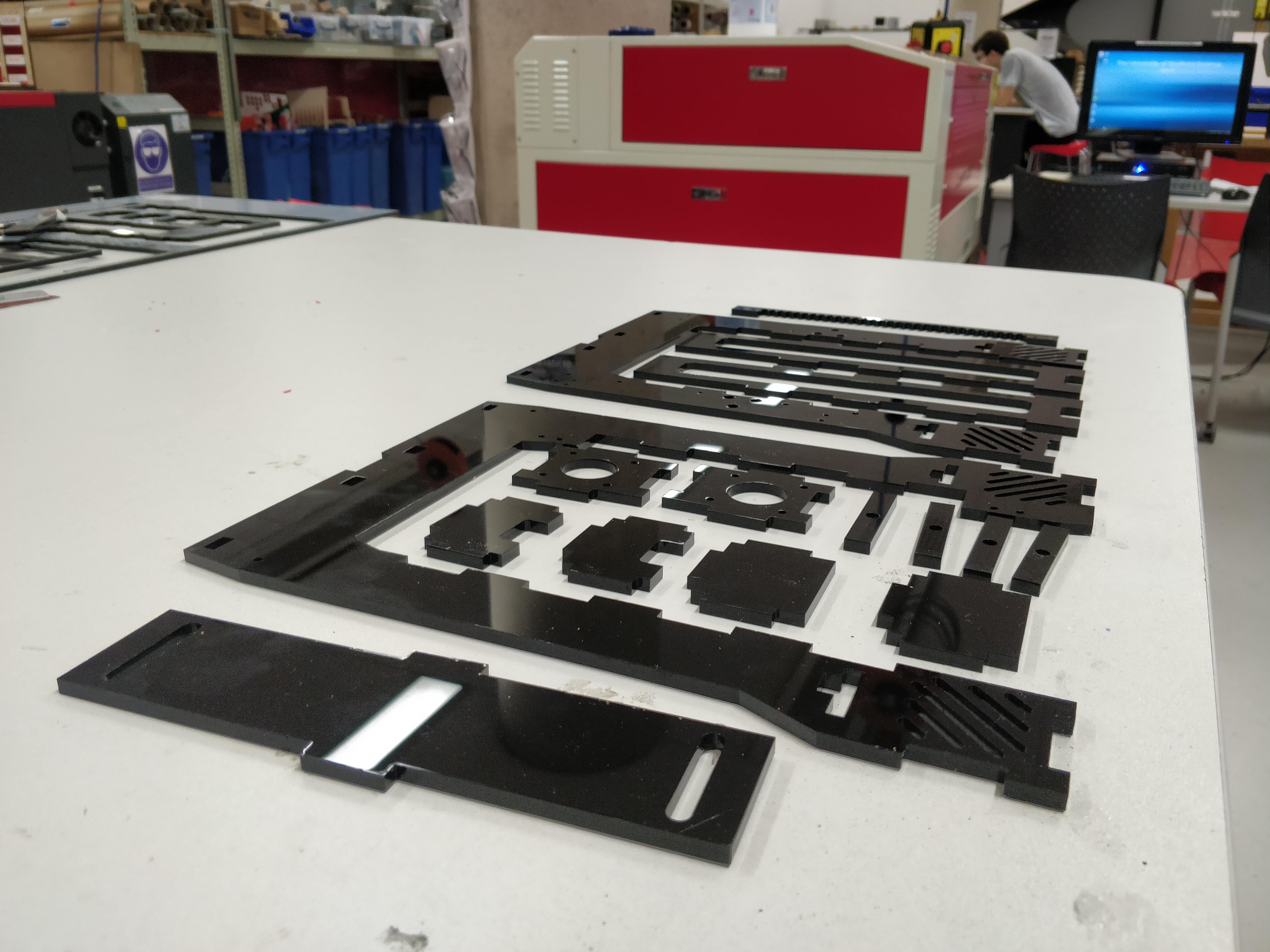
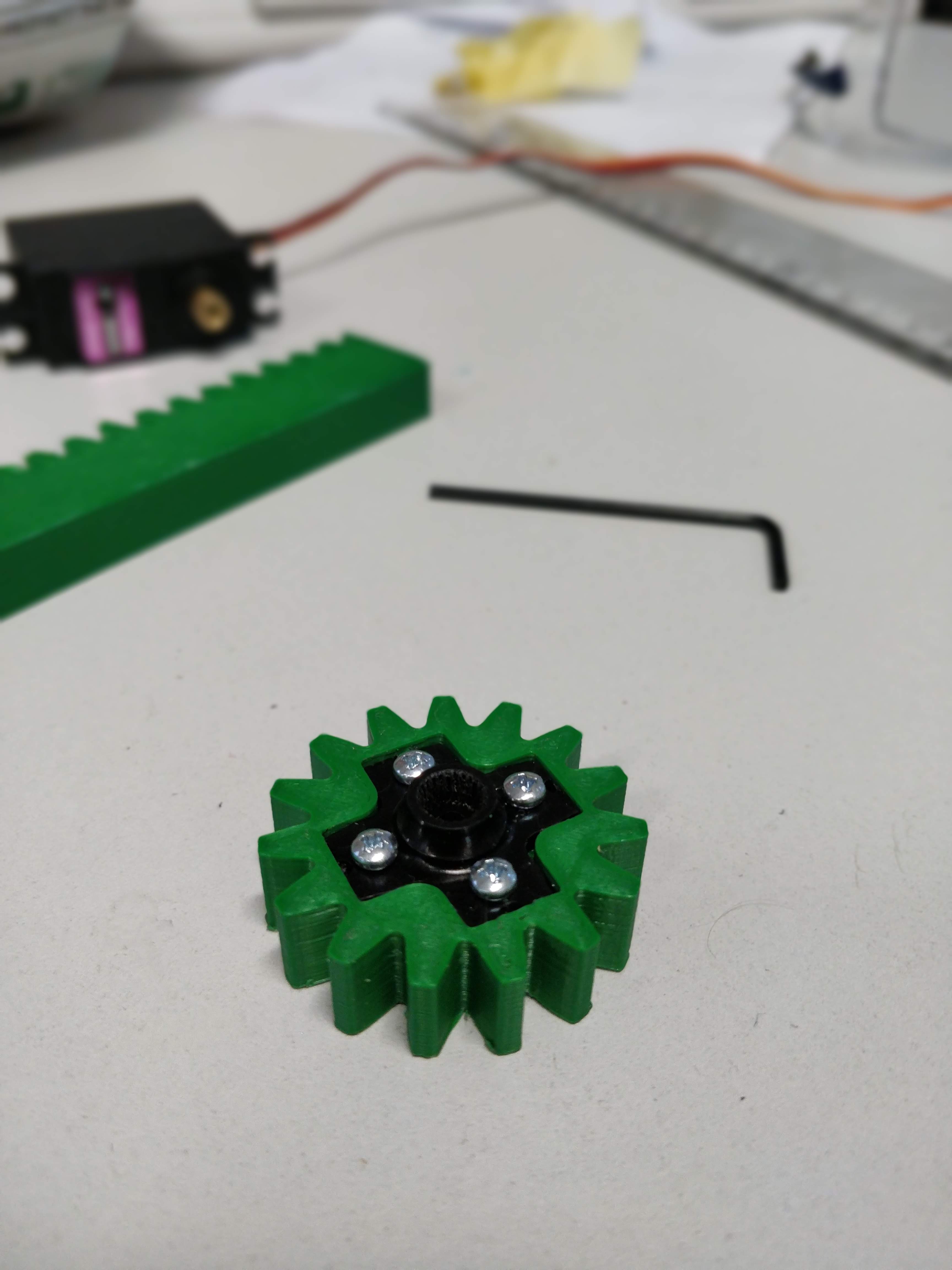
Crane Boom Designed and Built 24.03.2019
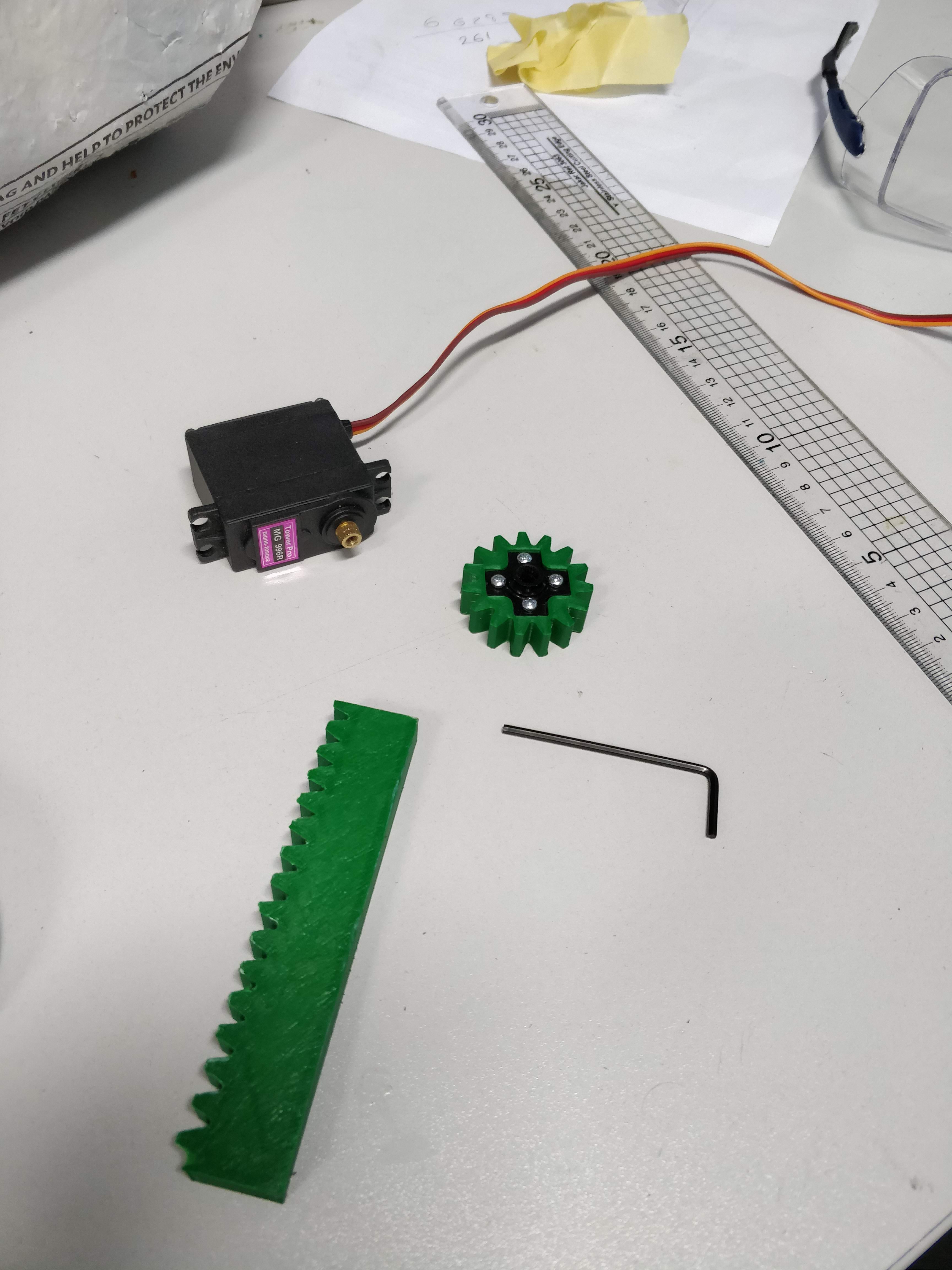
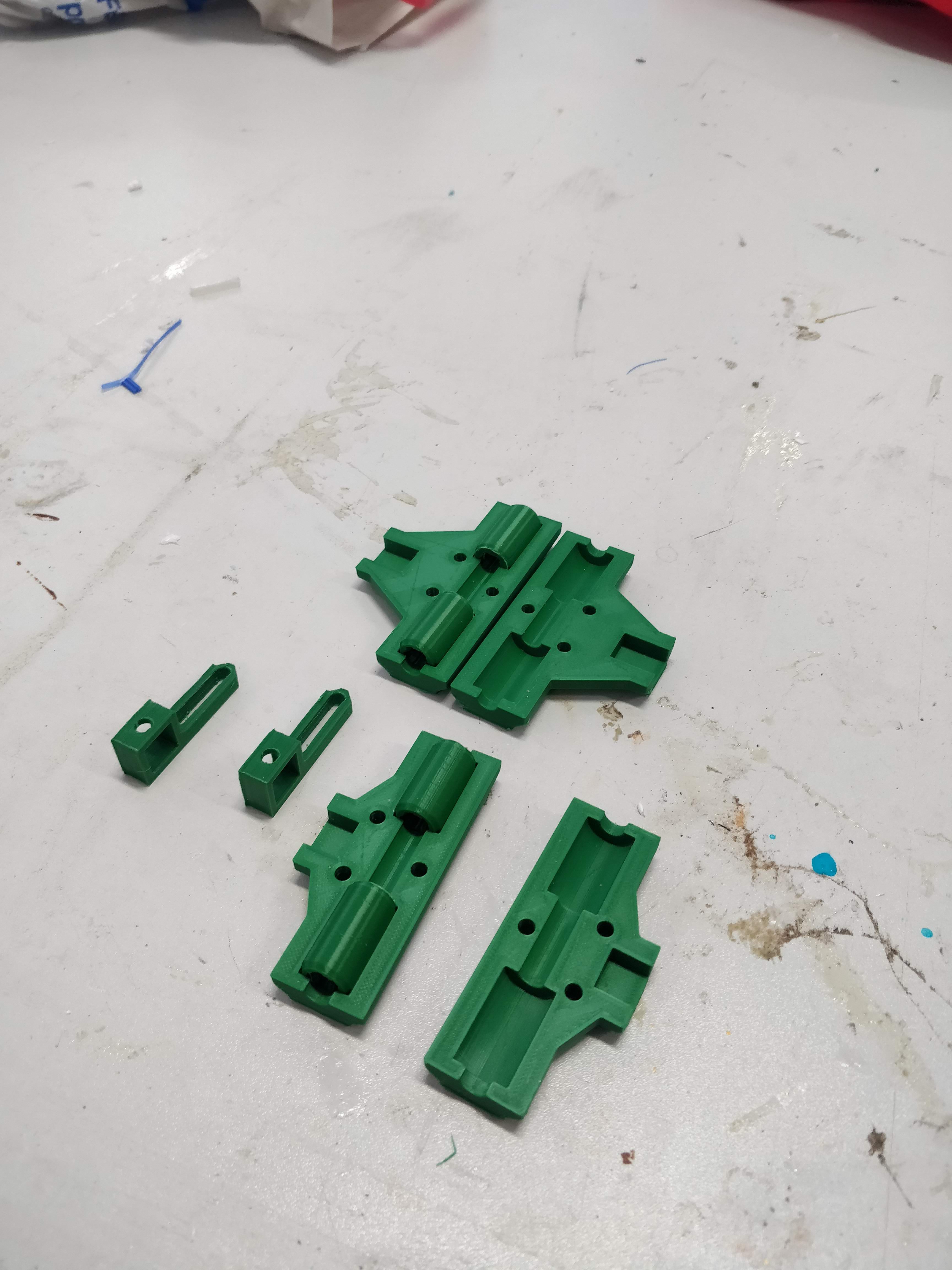
03/24/2019 at 14:50 • 0 commentsThe crane boom design is based on that of a 3d printer; inspired by the prusas in the iForge. It uses a continuous servo and a rack and pinion to lift the boom. The design uses 3D printed bearings and bearing housings to locate the boom and allow sliding.
These pictures speak more than my words here:
![]()
![]()
![]()
![]()
![]()
![]()
![]()
-
Program Loop Timing Issues 15.03.2019
03/24/2019 at 14:13 • 0 commentsI had noticed that the accelerometer had a strange offset in addition to the gyro drift I had encountered. Therefore, I conducted some more rigorous tests to look at the signal to assess the gyro drift and the accelerometer readings simultaneously. The testing method was as follows:
With the code set to record the accelerometer angle, gyro angle & overall pitch angle...
1) Undisturbed testing...
- Robot placed on stand
- Reset the arduino
- Start timer on my phone as soon as the serial monitor started outputting data
- When timer reached 30s, pull USB cable from arduino to terminate serial communication
- Record data in .txt file
- Clear the Serial Monitor
- Repeat until 5 sets of data have been collected
2) Disturbed testing...
- Same as above but between 10s and 20s of each repeat shake the robot
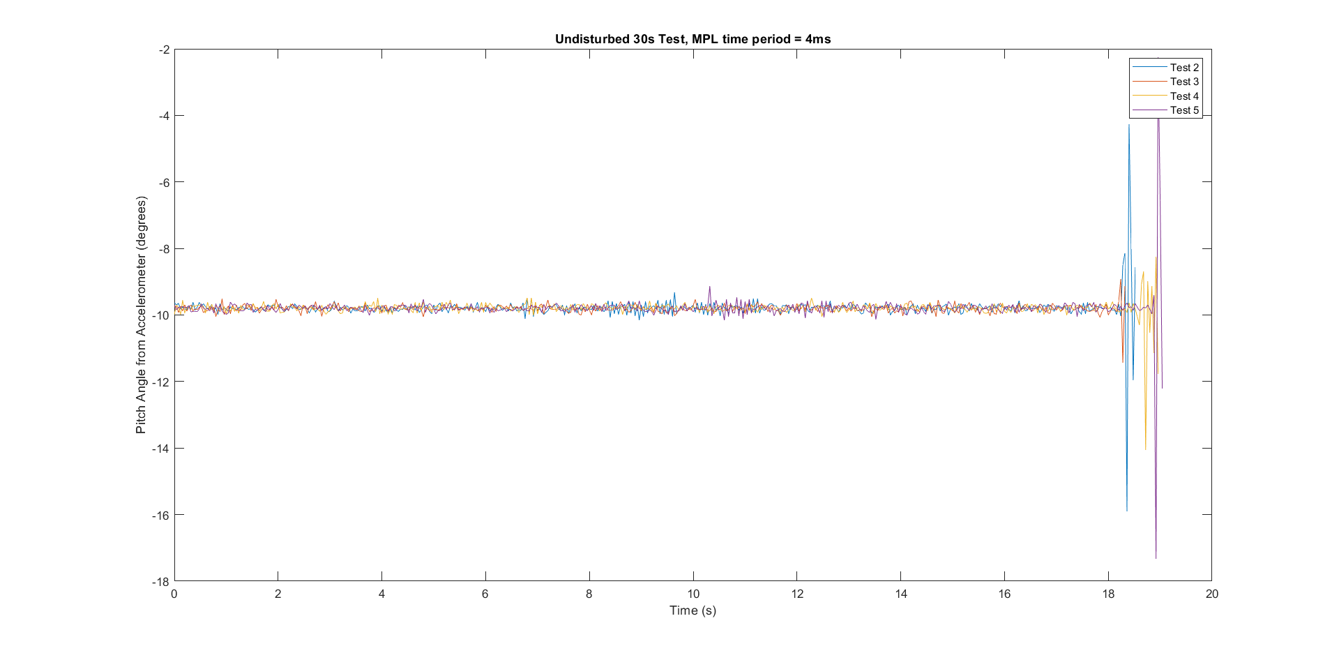
See the below data for the accelerometer angle...
Undisturbed data:
![]()
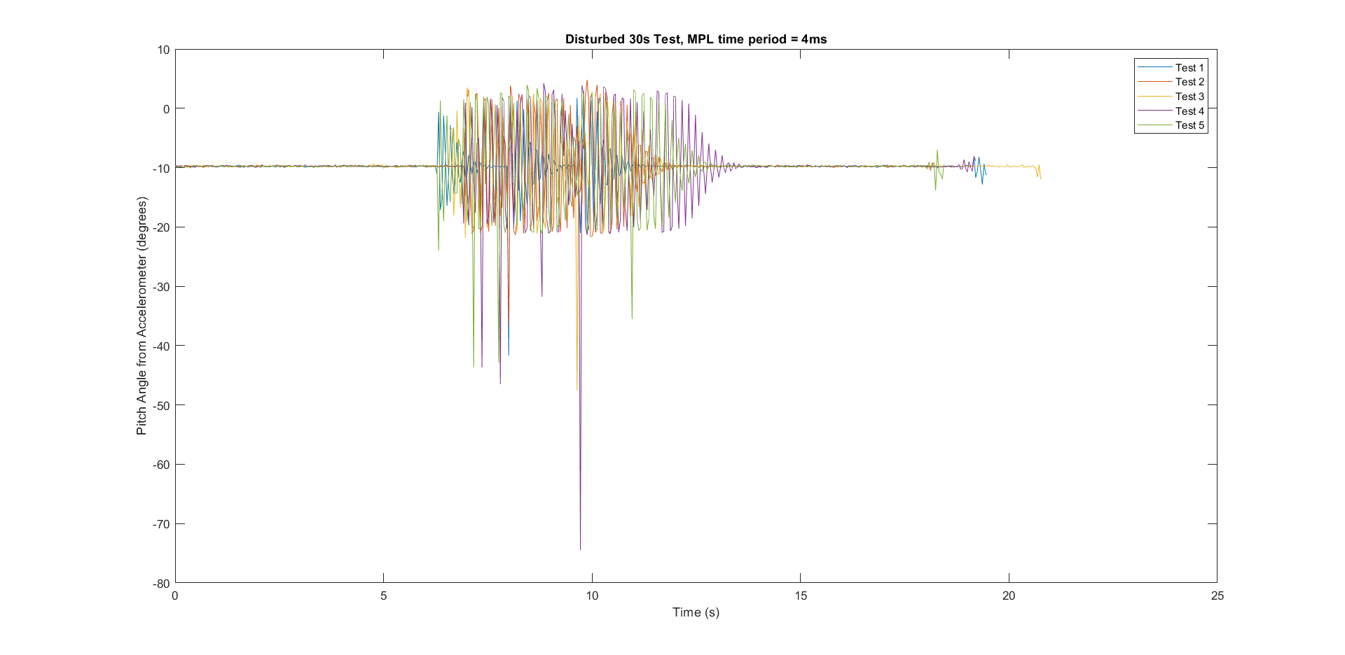
Disturbed data:
![]()
Observations:
- Immediately I could see that the data did not align with the experiment time (the data from both experiments apparently only went up to about 20s despite me knowing I recorded data for 30s). My conclusion was that the MPL (main program loop) must be exceeding its time limit; the code was taking longer to run than anticipated.
- The accelerometer has a constant offset of around 10 degrees; this is unchanged by excitation and will be dealt with by centering the signal about 0 by subtracting the mean from this data.
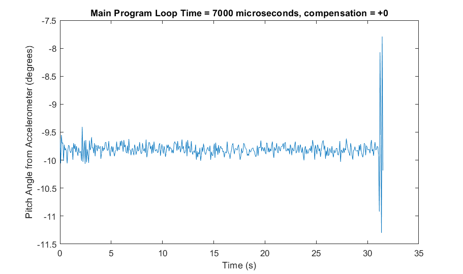
Further experimentation to verify the above:
I made the MPL time period a variable and increased it from 4ms to 7ms and the result was as follows:
![]()
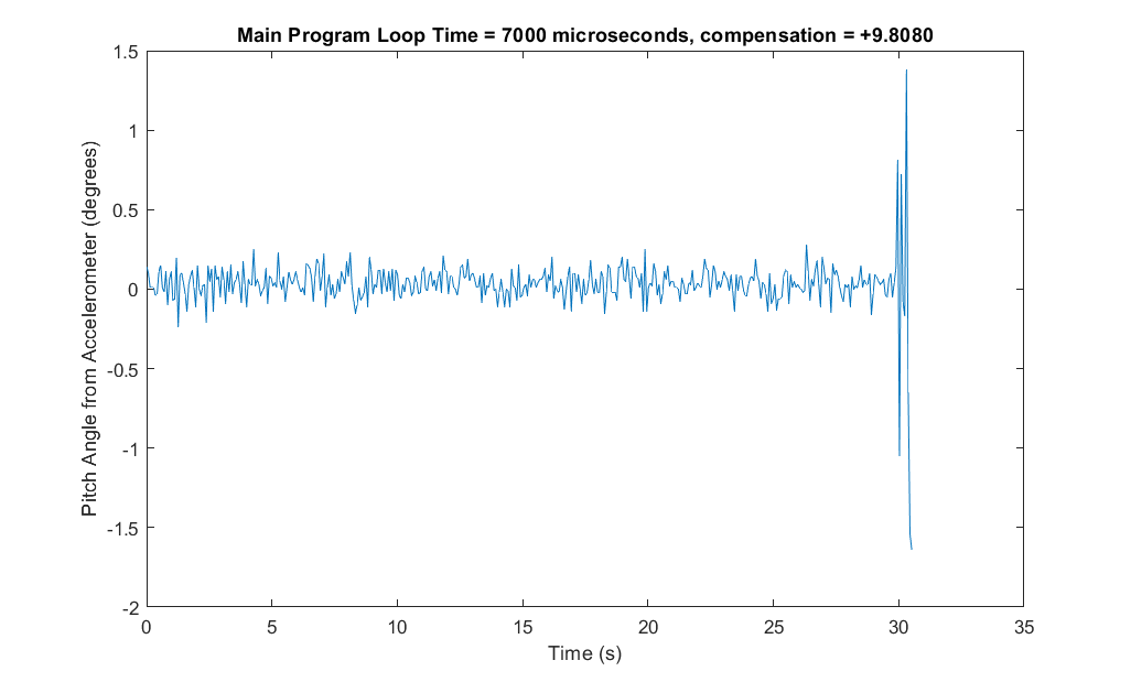
I subtracted the mean from the above data and took more readings:
![]()
As a result of the above changes, the robot needed some more PID tuning (MPL period resulted in new gain values needed), but looked very promising in terms of stability.
Because I am coming to the end of my project timescale, I decided to move on to the mechanical design of the crane system despite the remaining balancing perfromance issues. The robot works well enough for proof of concept. -
Translation Control First Attempt 13.03.2019
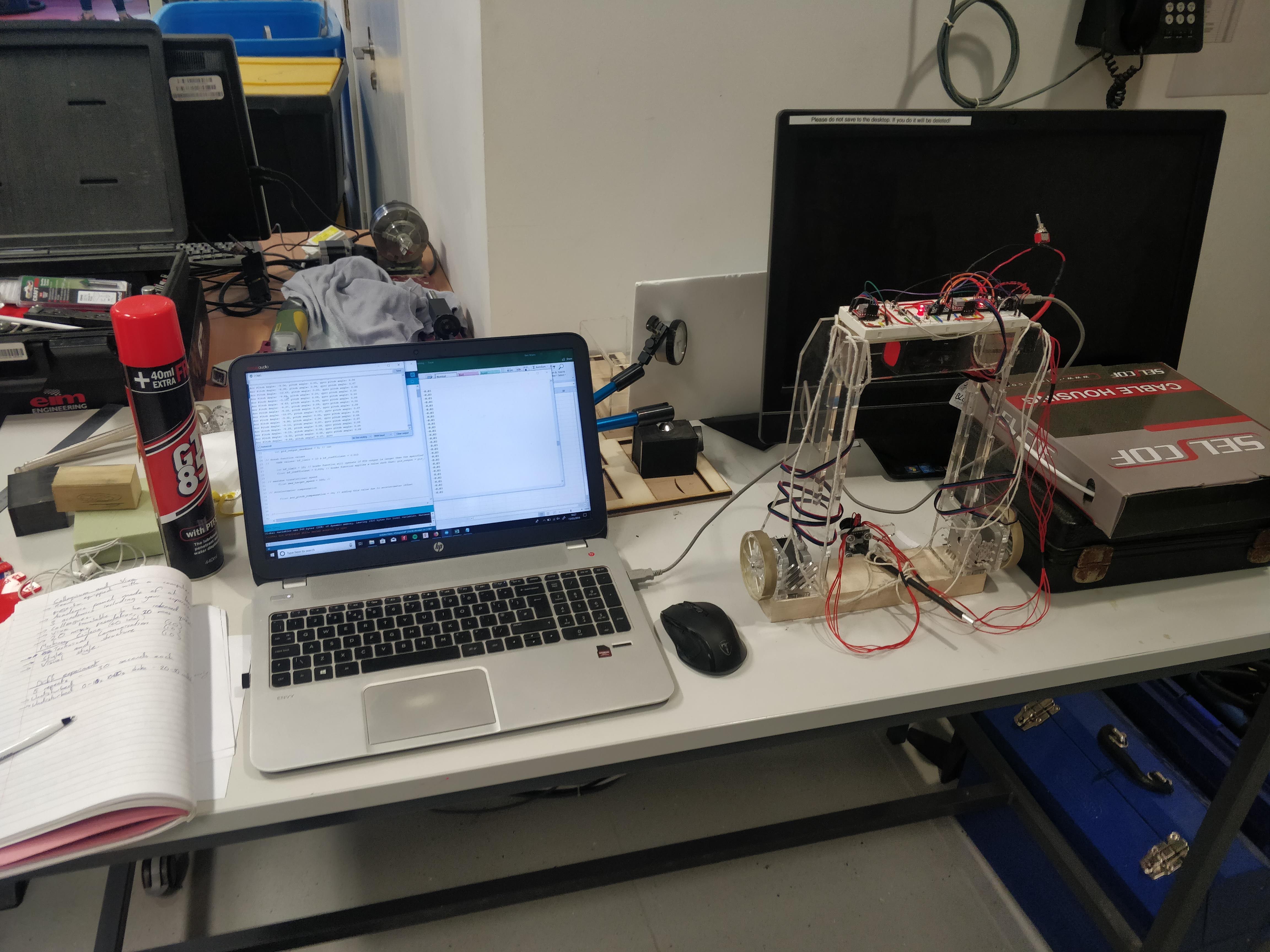
03/13/2019 at 17:44 • 0 commentsAfter yesterday's attempt at adding steering to the robot resulted in some instability ( probably due to the added computational power of having seperate throttling variables). I decided to revert to the previous code and add only forwards and backwards control to see how this affected the stability.
![]()
I have solved my logistic problem by adding a string harness for the robot to my wired controller (you can sort of see it in the above picture), check out the videos to see how much easier it is making the testing; no more need for a friend chasing the robot around. The robot moves forwards or backwards by tilting itself into the direction it needs to travel. The results were very promising. Please see this video link.
The robot can drive in both directions but drives slowly in the direction against the way it tends to drift and slightly too fast in the other direction. I am fairly confident now that the robot will operate as intended when I sort these sensor issues out! Today I also conducted some more rigorous testing on the robot and have a good amount of data with repeats that I will analyse in the hope of sorting these issues out. I will post any significant progress on here.
-
First Steering Tests 12.03.2019
03/12/2019 at 19:41 • 0 commentsToday I modified the code to give the robot some steering capability. This meant creating separate throttling variables for each motor whereas previously I had just one variable that controlled both motors simultaneously. Now when the joystick is pushed left or right the code adds to the left and subtracts from the right motor's PID value to result in different throttling between motors.
The robot can now steer but is much less reliable! Strangely, the robot has become less stable as a result of me adding this capability; it is nowhere near as stable as before with the same PID values. I am not sure why the tuning should be different but I suppose I have essentially doubled the computation needed in the subroutine than controls the motors. I have had some attempts at tuning with varied success. It is not being told to move forwards by the way, this is still an effect of drift I think. Please check out the videos below...P.S. the robot has become a bit of a logistical challenge to test, I think you'll find these amusing :)
-
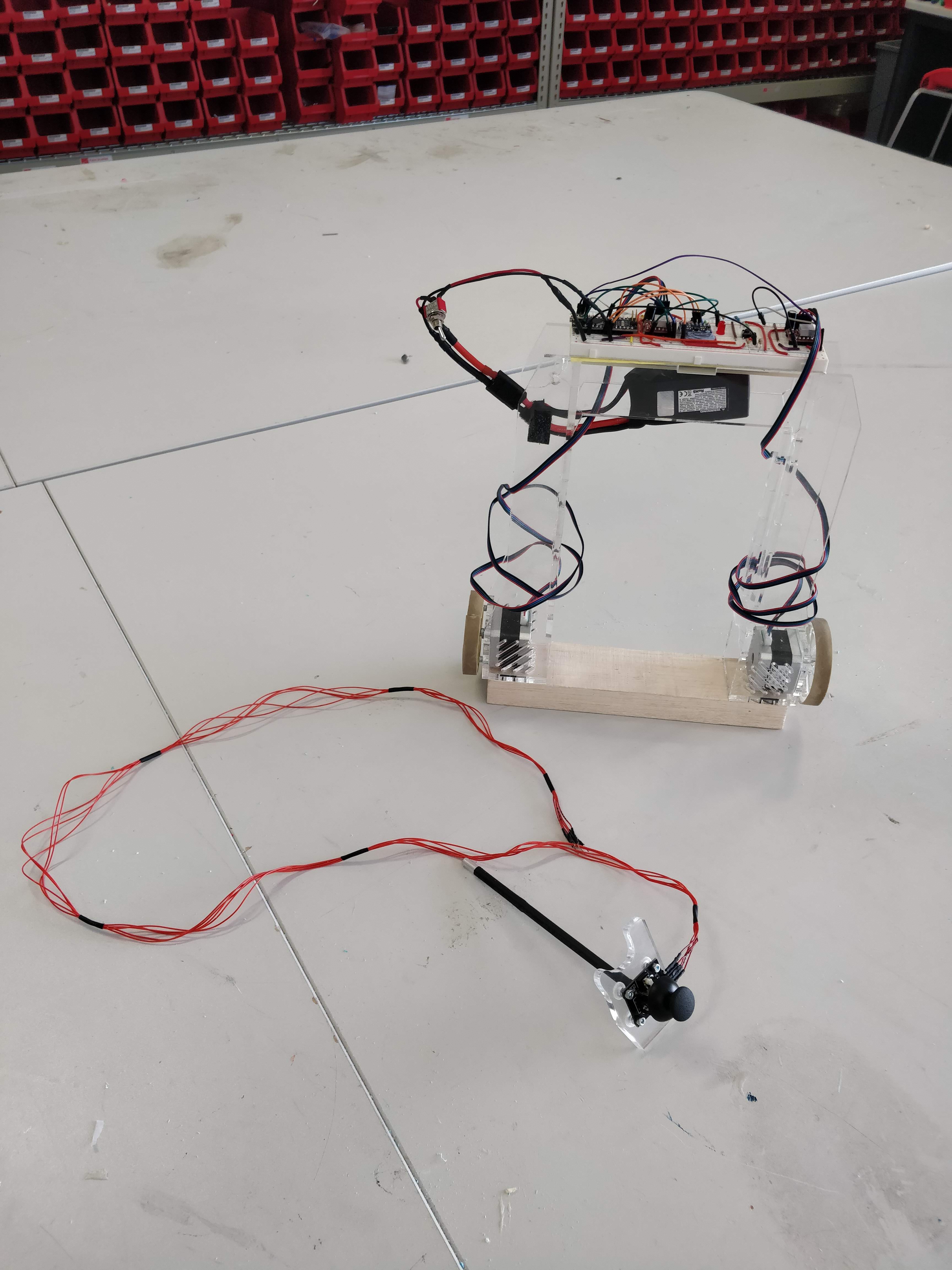
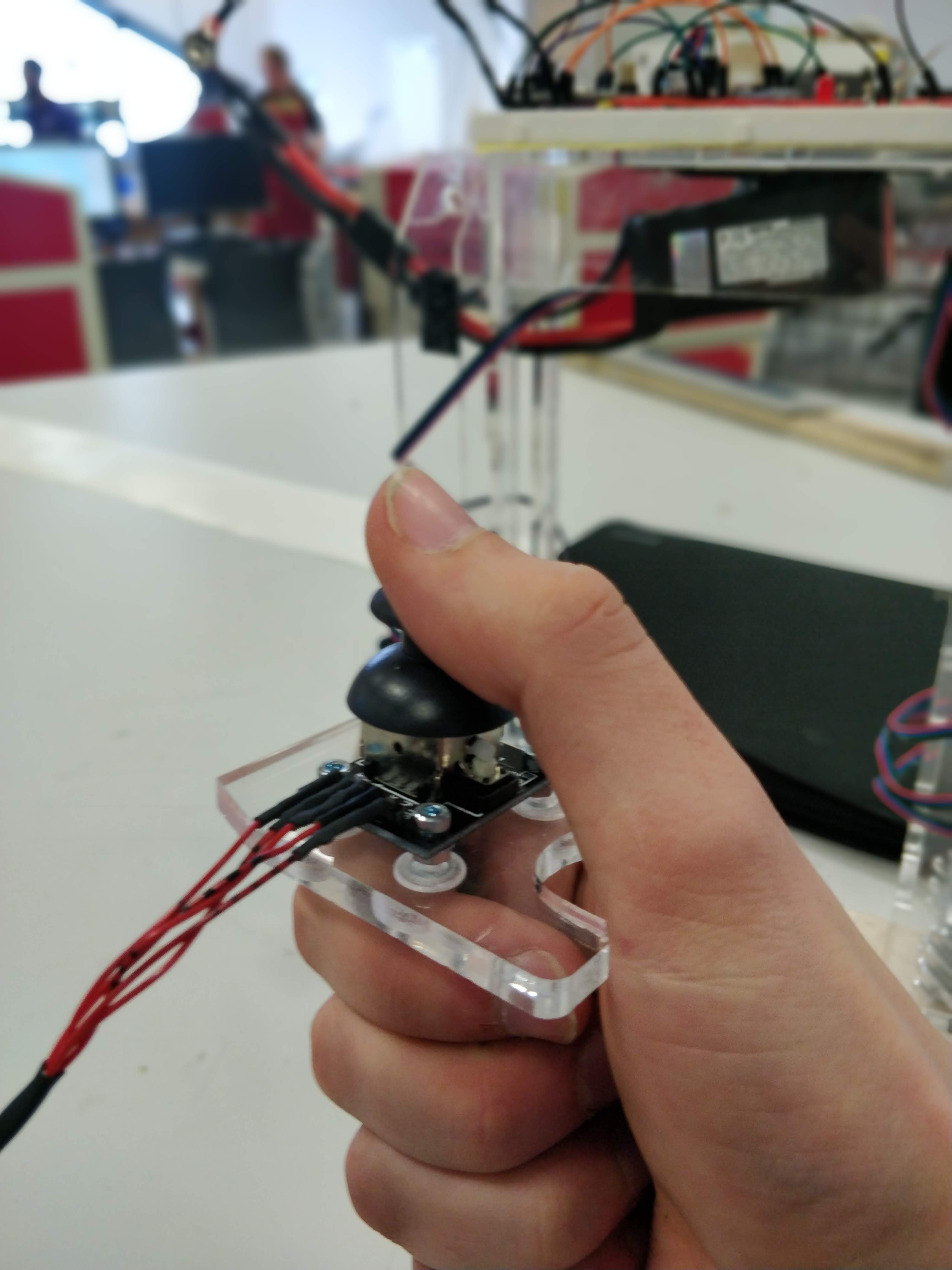
Joystick Built
03/11/2019 at 11:12 • 0 commentsJust a short post to say that I have made a joystick holder (with approximately 1m of cable) now and this week I will be working on:
1) getting the robot turning
2) getting the robot moving backwards and forwards
![]()
![]()
"Straddle Crane" Self-Balancing Robot
I am aiming to create a new self-balancing robot that can drive around an object, pick it up, carry it and offload it.