-
1Plan
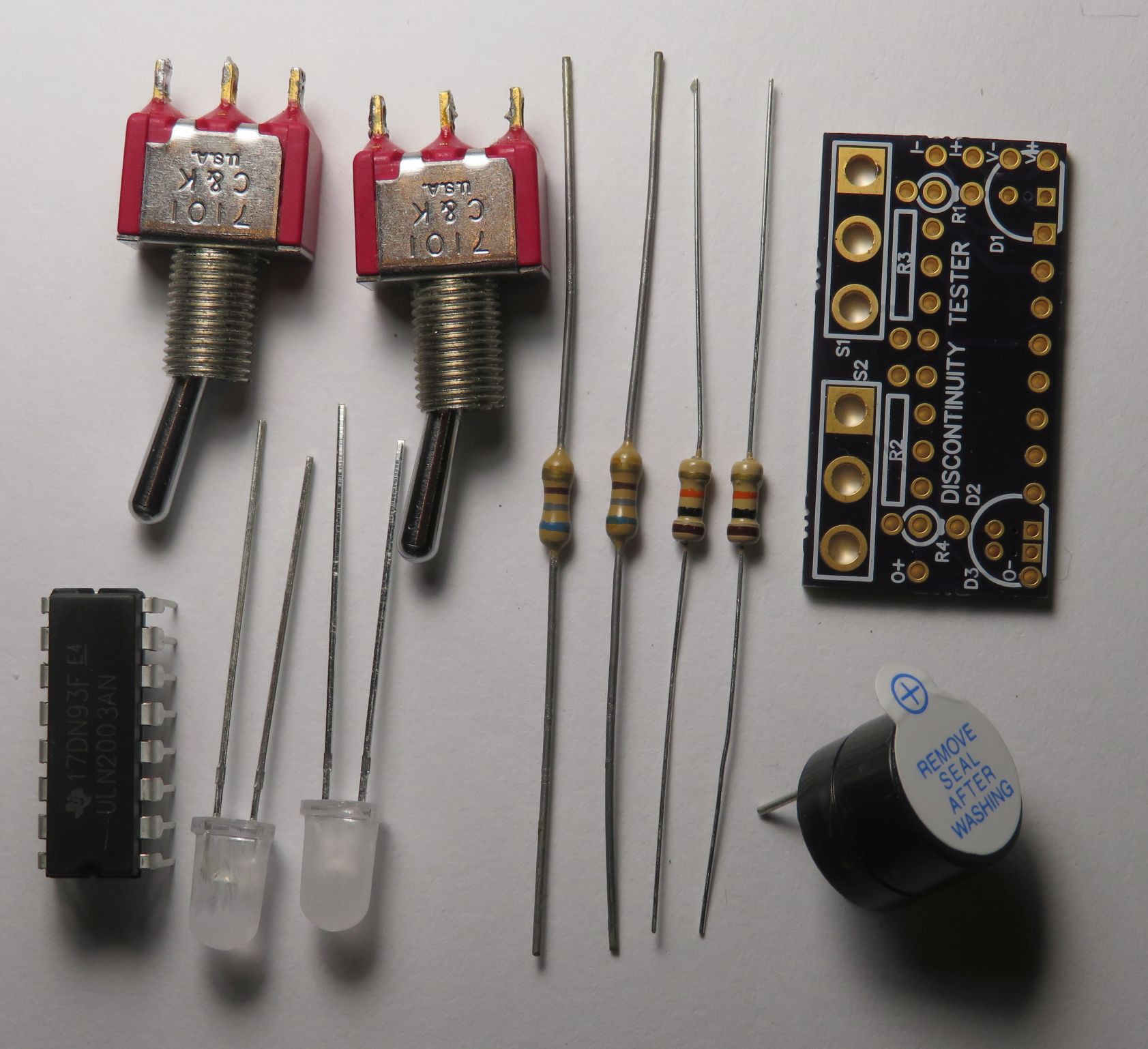
Decide on what configuration to build – switch options, LED options, power supply type and voltage. Get the components, including non-PCB components like a box, test probe connections, and power source.
In my opinion, LEDs with white diffused lenses provide the best contrast and most uniform viewing angle, but they are not widely available. I made clear lenses into diffuse lenses by scuffing up the lenses with sandpaper or an emery board.
![]()
-
2Drill Front Panel Holes
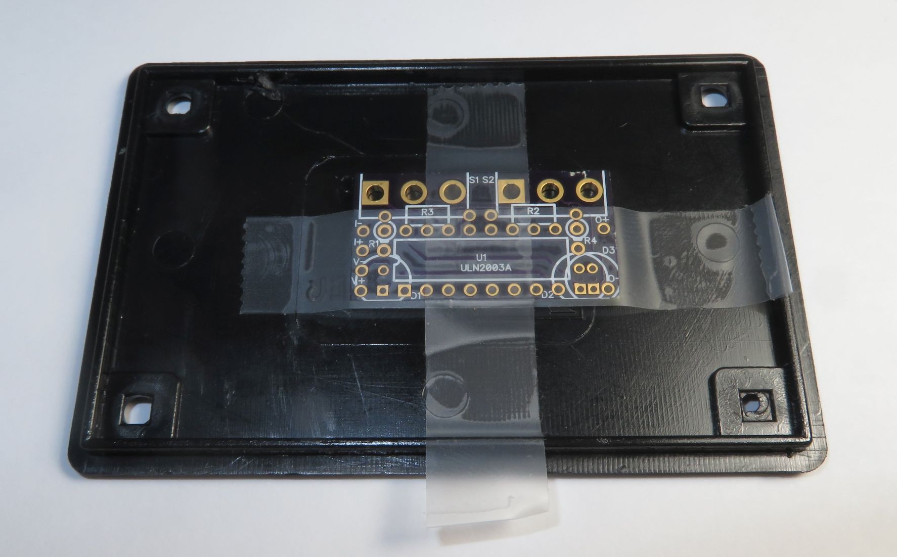
Tape a PCB to the front panel to use as a drill guide for drilling holes in the front panel. It works best in my opinion to have the IC (U1) and the top side of the PCB facing inward as shown in the photos. Drill initial holes smaller than the final hole size. For the switch(es), the PCB hole size is 2.1 mm (.083”), so use a #45 (.082”) or similar drill in the center hole of the switch. For the LEDs, there are little 0.5 mm (.020”) holes centered on the LEDs between the LED pads. Too big of a drill will compromise the LED pads, so use a very small drill if you want to use the board to build a tester. Once the initial holes are drilled, untape the PCB from the front panel and drill the holes to the final size.
![]()
![]()
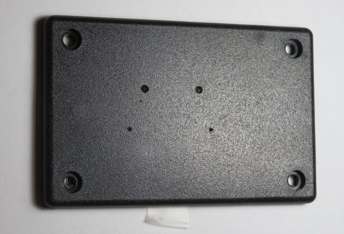
Drill other holes for test input connections and power supply.
Fit the PCB, switches, LEDs, and front panel together for fit. Make any adjustments needed, for example hole sizes. Then take apart.
![]()
-
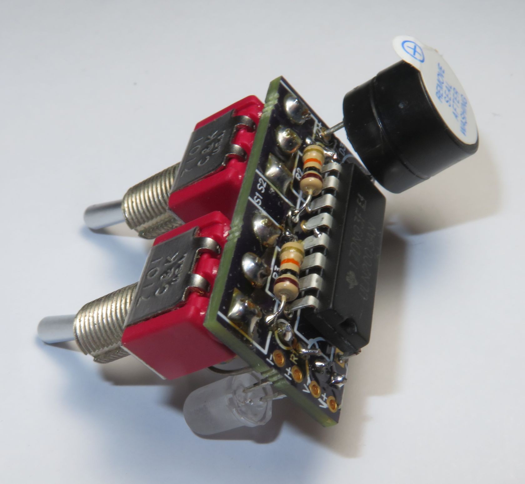
3Add components to PCB
Assemble the PCB. Suggested ordering and PCB side for soldering components is:
-
IC U1, top side
-
Resistors R2, R3, top side
-
Resistors R1, R4, bottom side
-
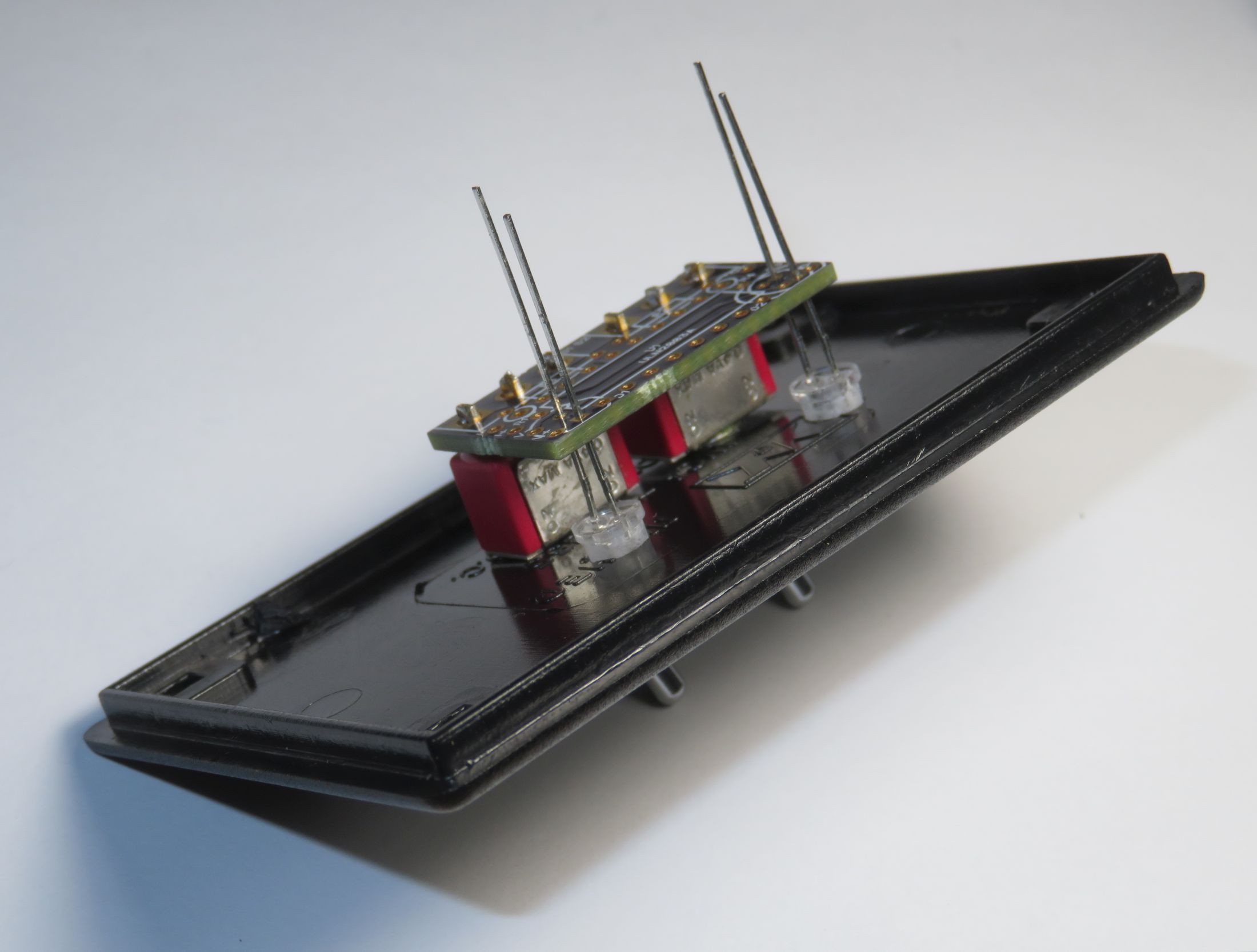
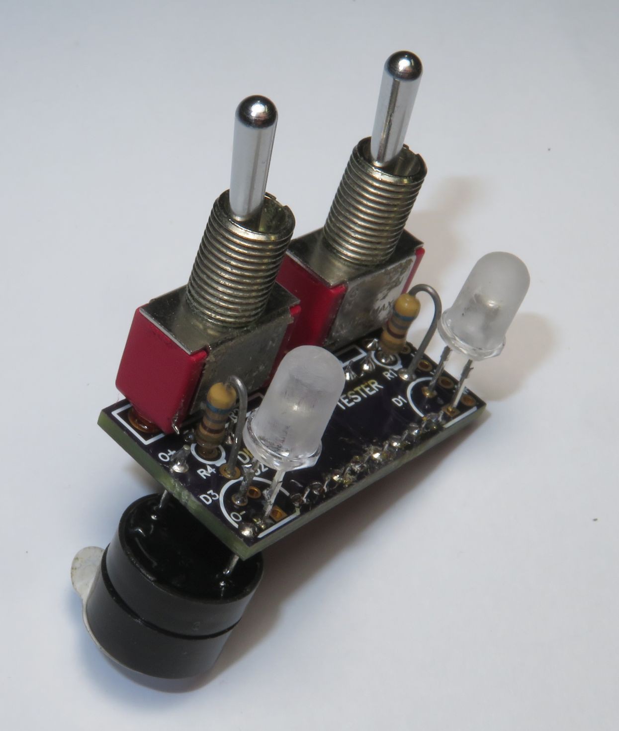
Switches and LEDs S1, S2, D1, D2/3, bottom side. Fit into PCB, then fit into front panel, then solder, then remove from front panel. Be sure to put the LEDs in the correct way. The longer lead is ‘+’ and goes away from the edge of the board. The flat on the LED body goes near the edge of the board.
-
Beeper/buzzer into holes labeled O+ and O- if mounting directly to the PCB. Observe polarity, the longer lead is likely ‘+’.
-
Power supply connections to V+ and V-, and test input connections to I+ and I-. Or assemble into the enclosure before soldering these.
![]()
![]()
-
-
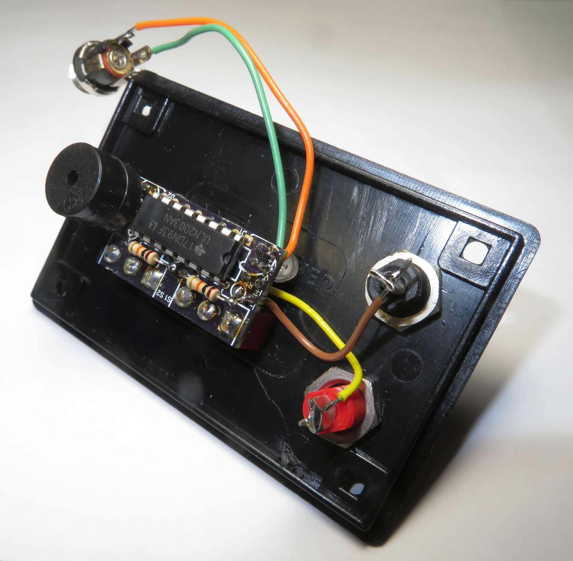
4Final Assemby
Attach the board to the front panel and attach power supply and test input connections. Assemble the enclosure. Test, debug, use.
![]()
![]()
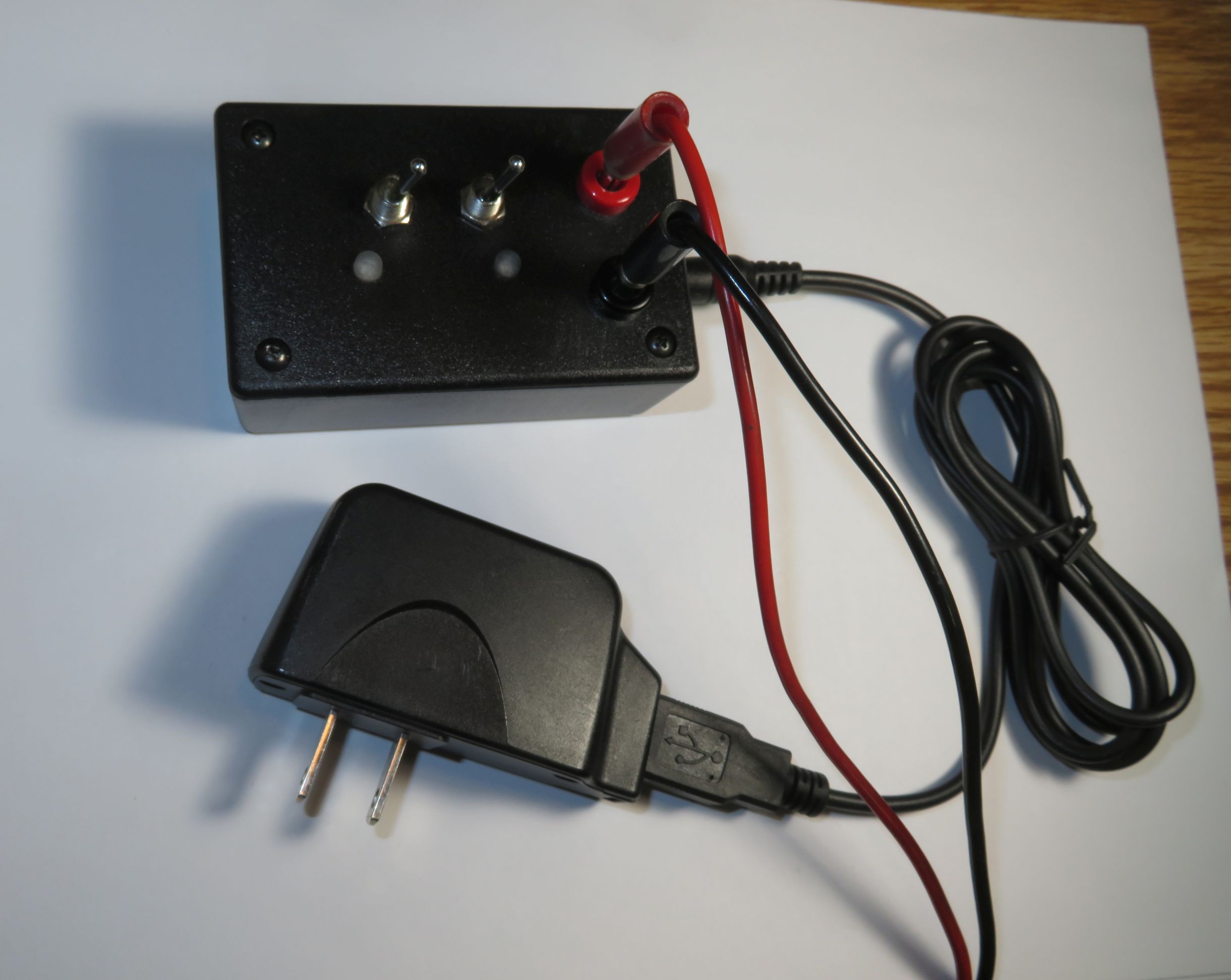
Discontinuity / Continuity Tester
Turn on a light and optionally a beeper for continuity (conduction) or for discontinuity (open circuit)
Discussions
Become a Hackaday.io Member
Create an account to leave a comment. Already have an account? Log In.