 MaBe42
-
1General:
Some details about building it. The decoration uses two independent astable multivibrators. I was thinking about using 555 based circuits but I thought to go really with just the basics would be nicer.
-
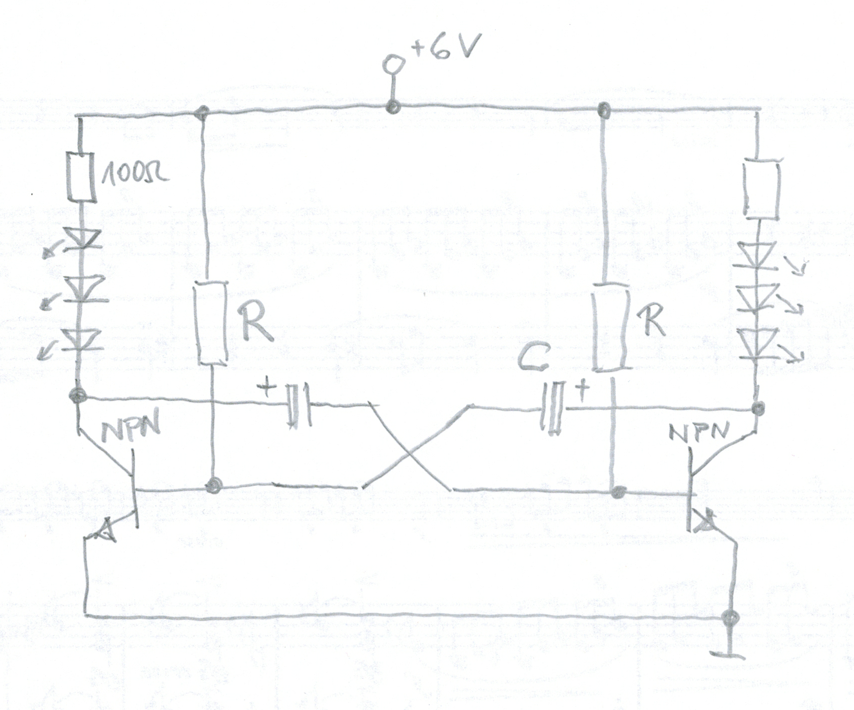
2The circuit:
![]()
-
3Choice of R and C:
in one of the circuits I use R=100k and C=47uF. In the other R=180k and C=33uF. The choices are rather arbitrary. They are mostly due to what I had lying around and I wanted to have time periods close to one another but not the same. The periods are roughly 3.2s for the first combination and 4.1s for the second one.
-
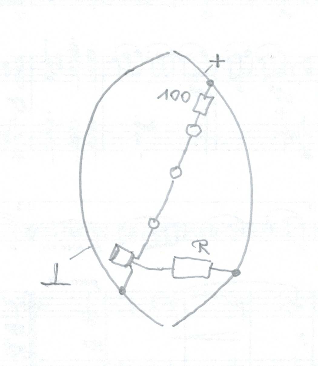
4Building:
I started by bending the two wires for the frame. One of them being + the other one -. So I could not solder them together. I used hot glue to bring them into a ball like shape. In the end I removed the hot glue again.
First I soldered three LEDs and a 100R resistor in series (four times).
Next I soldered the free LED end to the collector of the transistor.
I slightly bent the soldered components into a curved shape and soldered it to the frame.
Thereafter I soldered the resistor R between the basis of the transistor and +. This provided some stability to the structure. In particular after all four parts were soldered to the structure.
![]()
I decided to put the parts of one circuit on opposite faces of the structure.
Finally I soldered the condensors. A test with my lab power supply showed that everything worked as intended.
-
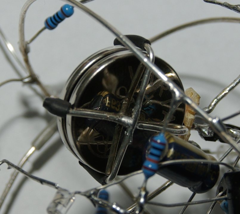
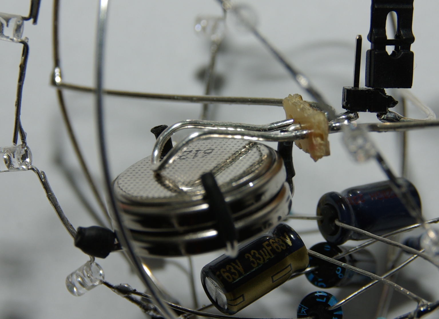
5The coin cell holder:
Well, instead of words I provide some pictures:
![]()
![]()
![]()
The isolations (which I made from heat shrink tube) are essentail to avoid shortening the lower cell. By bending the contact for the cell's minus pole I tried to get some pressure to hold the cells together. This works just well enough. The copper wire seems to be too soft to be able to achieve a spring-like behaviour.
Christmas tree decoration
A little blinking ball like object for season's decorations.

Discussions
Become a Hackaday.io Member
Create an account to leave a comment. Already have an account? Log In.