matseng
-
Test the sink of the sourcing
12/25/2018 at 22:36 • 0 commentsUnfortunately my latches are of the ALS family that can sink quite well (24 mA) but only have an official very measly 2.6 mA source capability so I realized that it might be a good idea to see if the display is bright enough when 1:6 multiplexing it using two 74ALS573 latches.
One of the latches will be connected to the anodes (segments) connected in parallel on all the displays, and the other latch have 6 of its outputs connected to the common cathodes of the displays.
It adds up quite well, the first latch might have to source current to up to eight segments @ 2.6 mA = 20.8 mA and then the second then will have to sink it and should be able to do that with its max 24 mA ports.
Of course these current limits are when the chip still can maintain VOH and VOL within their specs. If you don't care about the actual voltages then the chip can do better but not much due to internal resistances.
But the internal resistances in the drivers can work to my advantage. It allows me to hook up the display without any external current limiting resistors. This is *not* proper engineering and should not be done on any real products that other will use, but since this is just an internal hobby project I frankly don't care if I by torturing the drivers (and possibly the display) will shorten their lifespan a lot nor not. For the time being it works and the display is bright enough to be usable in indoor lightning and with 1:6 multiplexing the display at about 100Hz.
To test it I hooked up the displays/buttons combo and the driver IC bus with aa bunch of alligator clips and hooked some of the inputs of the drivers to an Arduino with even more alligator clips.

Testing brightness of the display at 1:6 muxxing -
Do not disturb my circles
12/23/2018 at 10:51 • 4 commentsIt is said that the last words uttered by Archimedes before being killed by a Roman soldier while drawing in the sand was "Nōlī turbāre circulōs meōs!" which translates to "Do not disturb my circles".
Well, my circles - or maybe I should say rings - that should have been put nice and straight on top of each other are for sure disturbed. ;-)
They ended up a bit more crooked and askew than I had hoped for, and while I can strive for perfection I don't demand it from myself, so for the time being this is good enough.Even if I had printed some jigs for holding the rings in place while soldering the resistors that I use as spacers/structure between the rings it was really hard to make it look even remotely nice.

3d-printed spacers for holding the rings while soldering Well, this is how the first cylinder ended up. Maybe the second cylinder with 16 rings for the address bus will be a bit prettier now that I have some experience with them.

3d-printed spacers for holding the rings while soldering -
First ICs
12/22/2018 at 21:22 • 0 commentsTo drive the display and read the keypad I need some I/O ports.
The display unit have in total eight anodes and six cathodes that have to be multiplexed by software. So for this I use two 74ALS573 Octal Latches. One will drive the anodes via resistors (of a rather low value due to the 1:6 muxing ratio) and the horrible source capability of the ALS family, and the other will directly drive the cathodes of the display.
The key matrix are organized as 6 columns x 4 rows, so I'll probably hook up the columns on the keyboard directly to the cathodes of the display and then connect the four rows to the 74ACT245 which is an Octal Bus Transceiver.
It would of course have been better to have an ACT as the display driver since it can both source and sink up to 24mA, but I didn't have one at hand so it is what it is....
Both the '573 and the '245 have a nice pinout structure. With inputs on one side and outputs on the other side straight over so they are easy to wire up in a bus. There are some other latches that the input and outputs are net to each other for each the eight internal latches. They are a nightmare to wire up nicely.
Now I just have to figure out where to put in and how to make some decent looking connections to the display/keypad unit...
Two 74575 octal latches and one 74245 octal transceiver 
The input pins and the VCC/GND are connected into a bus -
First combine
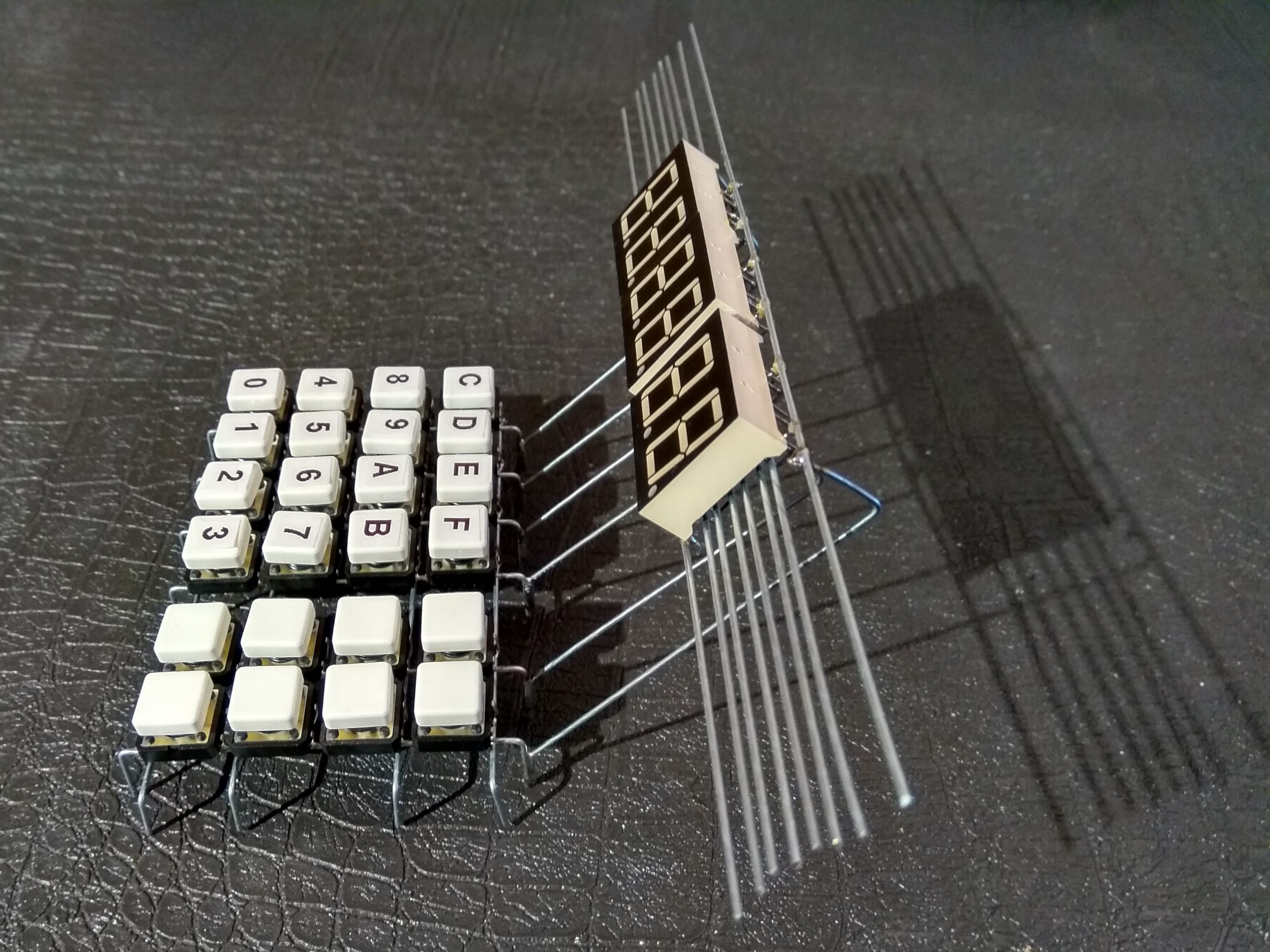
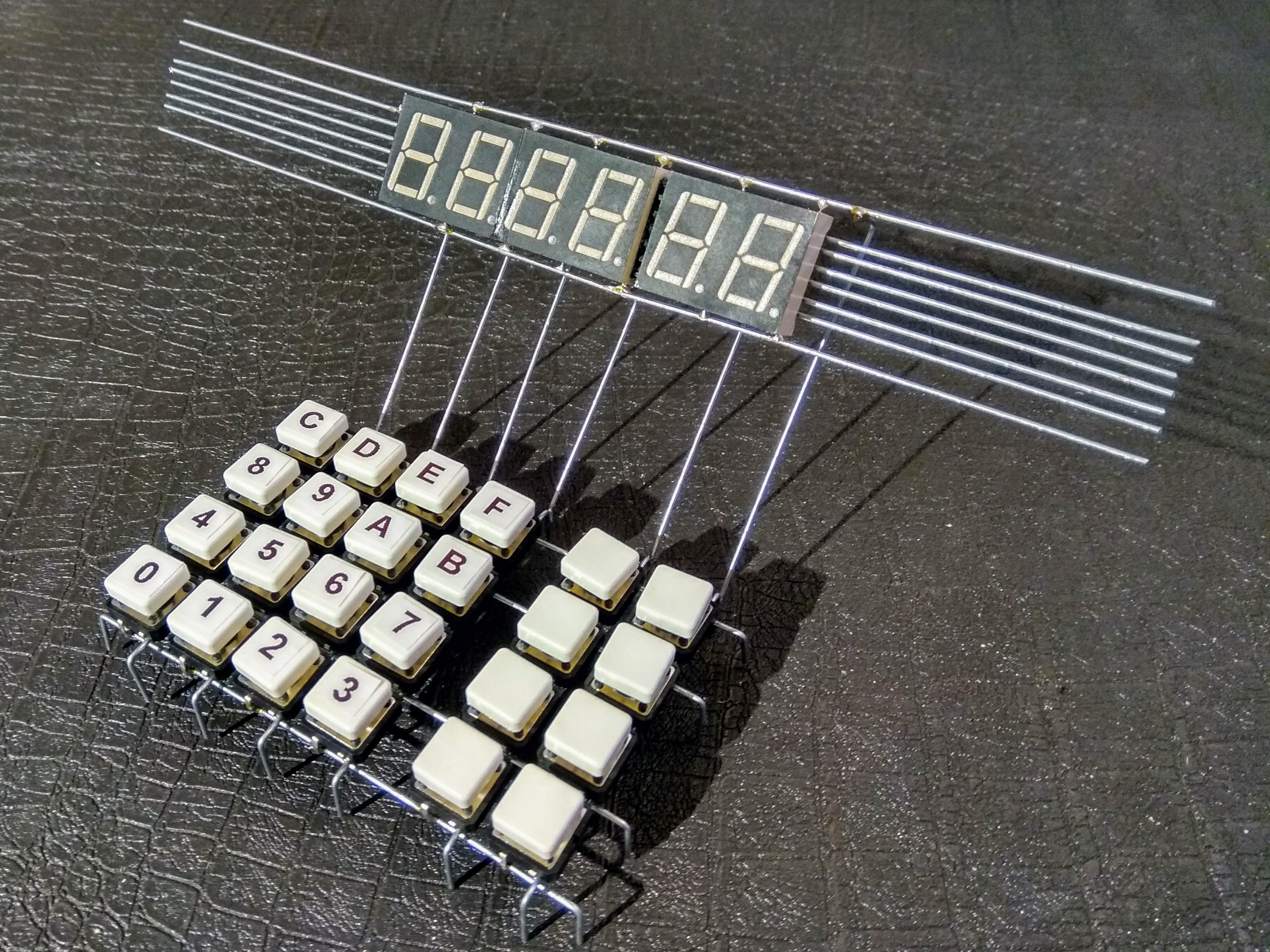
12/22/2018 at 00:01 • 0 commentsBefore starting to attach the ICs with latches and tranceivers for the keypad and the display I felt it was best to put those two together first.
Not being bound to the flat surface of a PCB I decided to have the display floating a bit above/behind the keypad and put at an angle.It turned out quite well. I think I'll keep most of the "cat-whiskers" and the edges of the display, it looks almost Art Deco in design. Maybe just trim them down a bit so they're even.
By pure luck the center of gravity ended up so the unit it stable and dosen't fall over, but I had planned to attach some rest/leg at the back of the displays going down to the table. Probably is a good idea to do that anyways.![]()
![]()
-
Gimme your digits
12/21/2018 at 22:10 • 0 commentsTonights excersize in straightening and soldering was to solder up the 7-segment displays. I had three 2-digit displays in a box - they turned out to be green instead of the more common red ones, but why not? Green is a nice color :-)
I cut up eight lengths of wire and stuck them between two small PCBs as a jig to keep the wires parallel and steady while soldering. I could fit 6 wires beneath the display and then put the two remaining wires outside of the display.
The inner six wire jigged up by pcbs The soldering was rather easy. I used thinner wires as jumpers between the four inner wires and the legs of the displays. I was a bit afraid that it would not be sturdy enough, but since each of the wires in the bus are connected to six pins on the displays the thinner wires are enough to hold them down steady.
I definitely need to clean up the joints from the flux - it looks a bit too messy to be really pretty right now.
Solder side of the displays I managed to get a bit of superglue on the face of the displays ;-( I'm not sure how to clean it up right now. Maybe I just can light sand the face, or maybe it'd be easier to put a green filter over the displays - that will increase the contrast as a bonus.

Display tops with glue residues -
The hex keypad
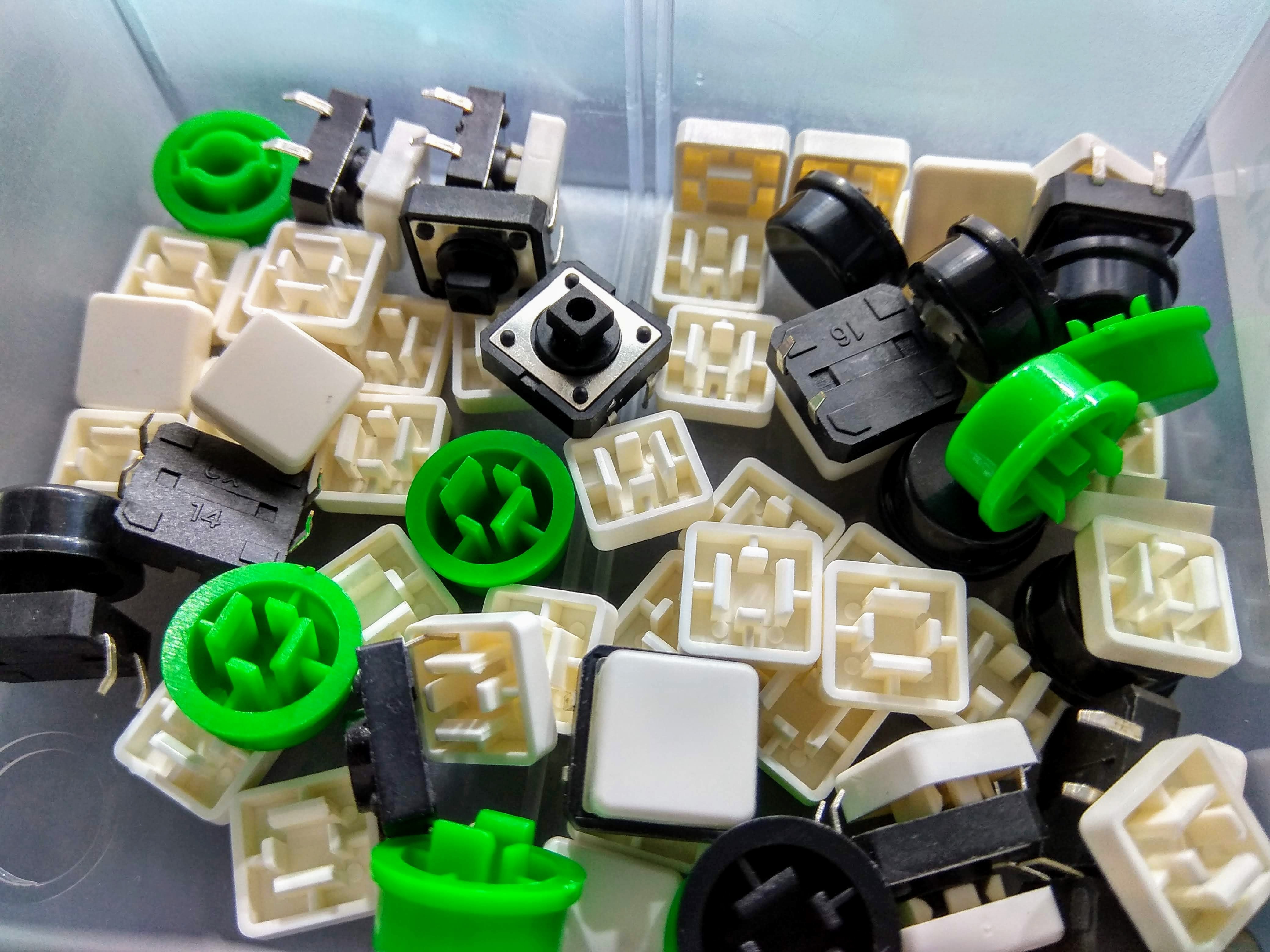
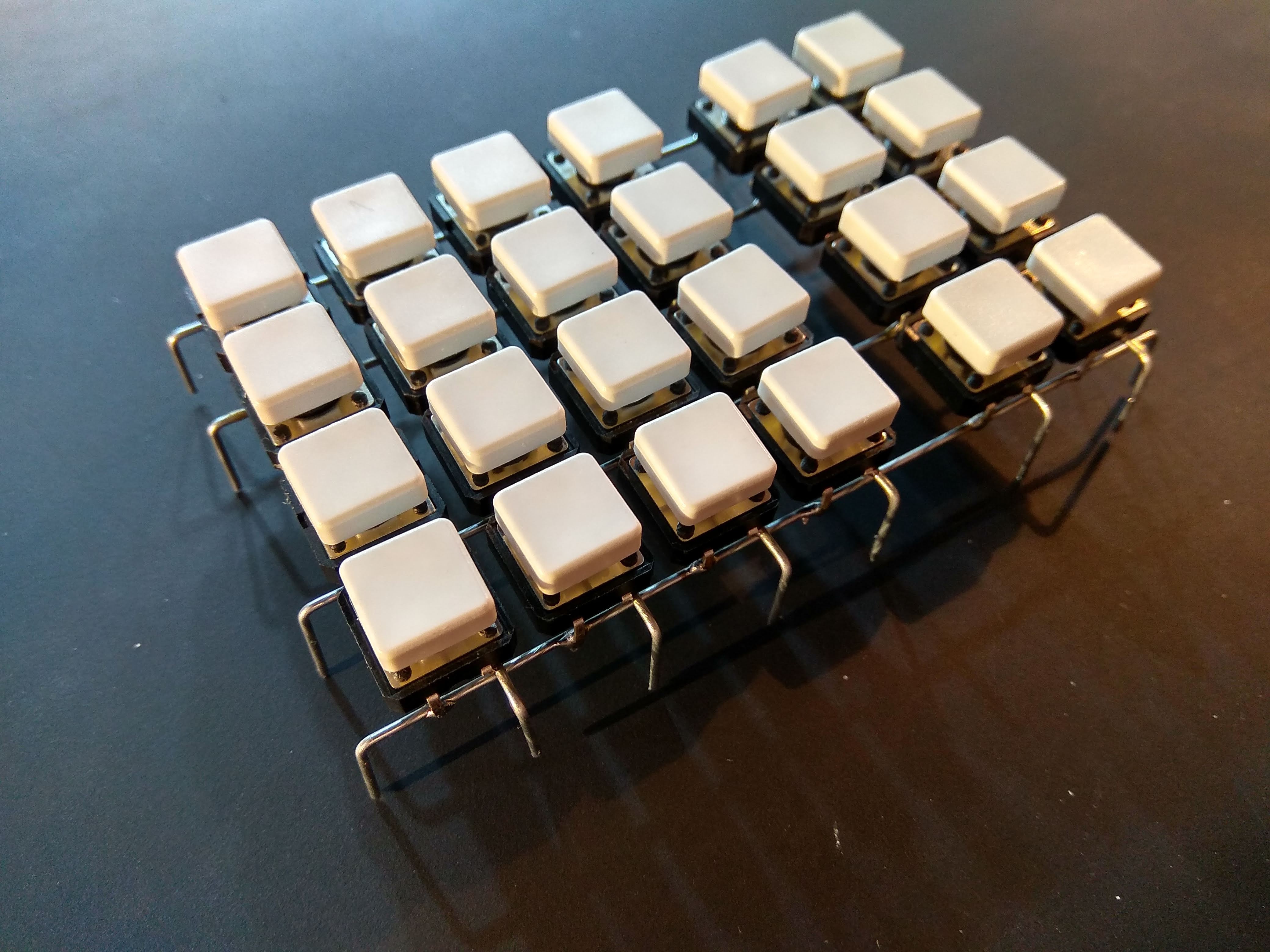
12/21/2018 at 10:53 • 3 commentsOriginally I had planned to use the ubiquitous 6x6mm tactile switches, but I found enough of the 12x12mm model with keycaps as leftovers from a previous project, so I decided to use them instead.
![]()
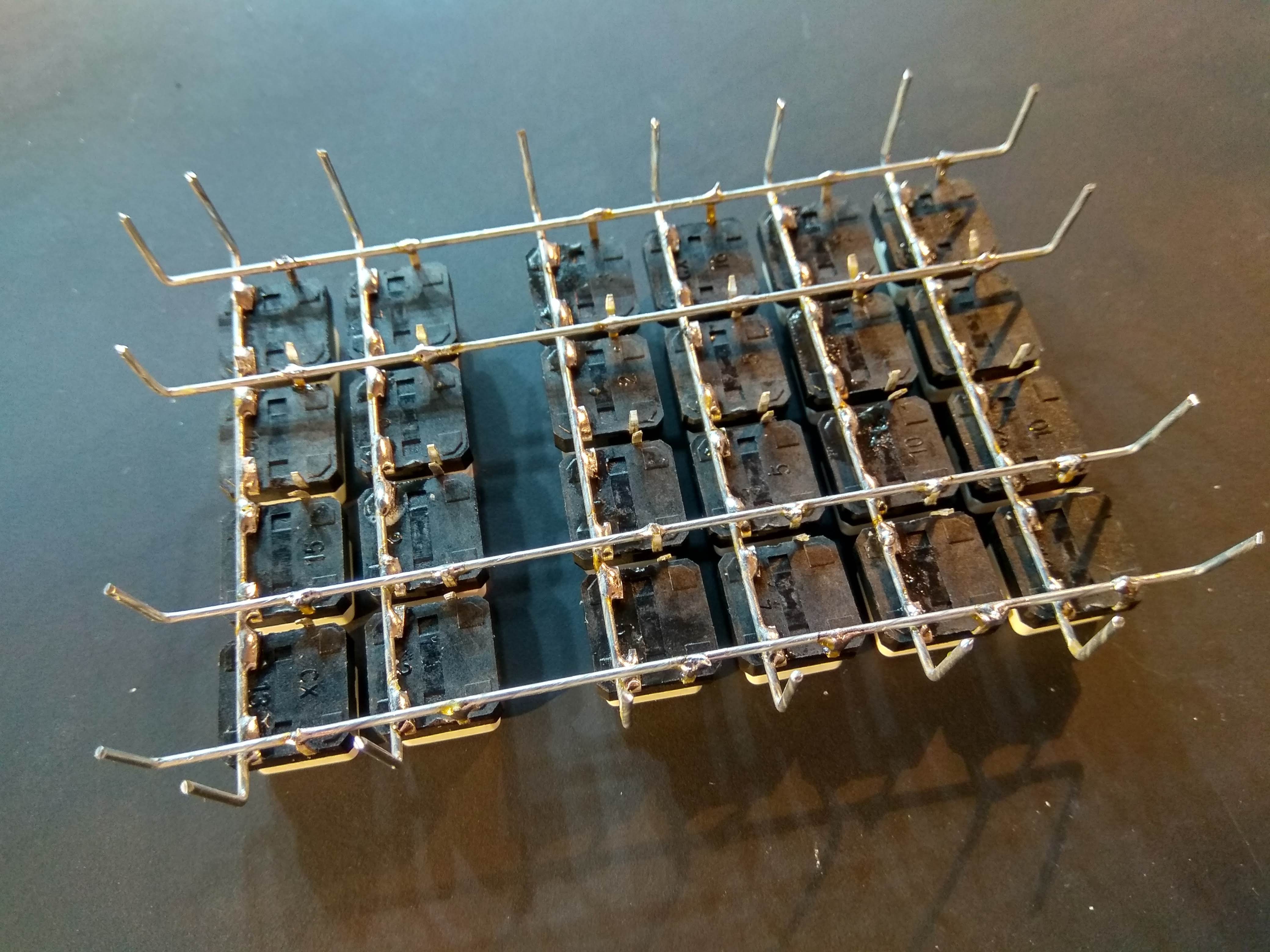
Soldering up 20+ switches in a nice orderly array would be a really hard thing. As the happy owner of a 3d-printer it was easy to model a jig in Fusion360 and print it. 30 minutes of modeling and 1.5 hours of printing later I had this in my hand.
3D-printed jig for 12mm tactile switches With the jig it was a piece of cake to just plonk down the switches into the holes and solder some newly straightened, cut and bent steel wires to them.
It ended up looking like this:
![]()
![]()
Nice huh? I'm quite pleased with this result, but unfortunately the stem on the switches can be rotated like 10-15 degrees in both directions so the keycaps end up all crooked after the keypad been used.
I might have to print some gridded overlay for the switches that will keep the caps lined up properly. Or else I just have to do some "homestyling" and straighten up the caps before taking photos of it so it looks nice and pretty. ;-) -
Making rings
12/21/2018 at 10:21 • 0 commentsMaking the 24 rings (16 for the address bus, and 8 for the data bus) rings was fairly easy. I just wrapped each ring around tin of paint that had a good circumference and snipped off the end of the wire (while stil on the tin) so that the ends overlapped 5 mm and then dabbed a small dot of flux and soldered the ends together.
Since I've got a nice Metcal soldering station and a really fat tip for the iron I could solder the joint in less than a second of dwell time. This means that I could use my fingers to press down on the wire very close to the joint without burning myself. Sometimes it pays off to invest a bit extra in good tools. :-)

Done and done - All the 24 rings for the buses I think I'll make a few more rings with a slightly smaller radius to use as a VCC/GND bus and put them in between the two other buses - behind the ICs.
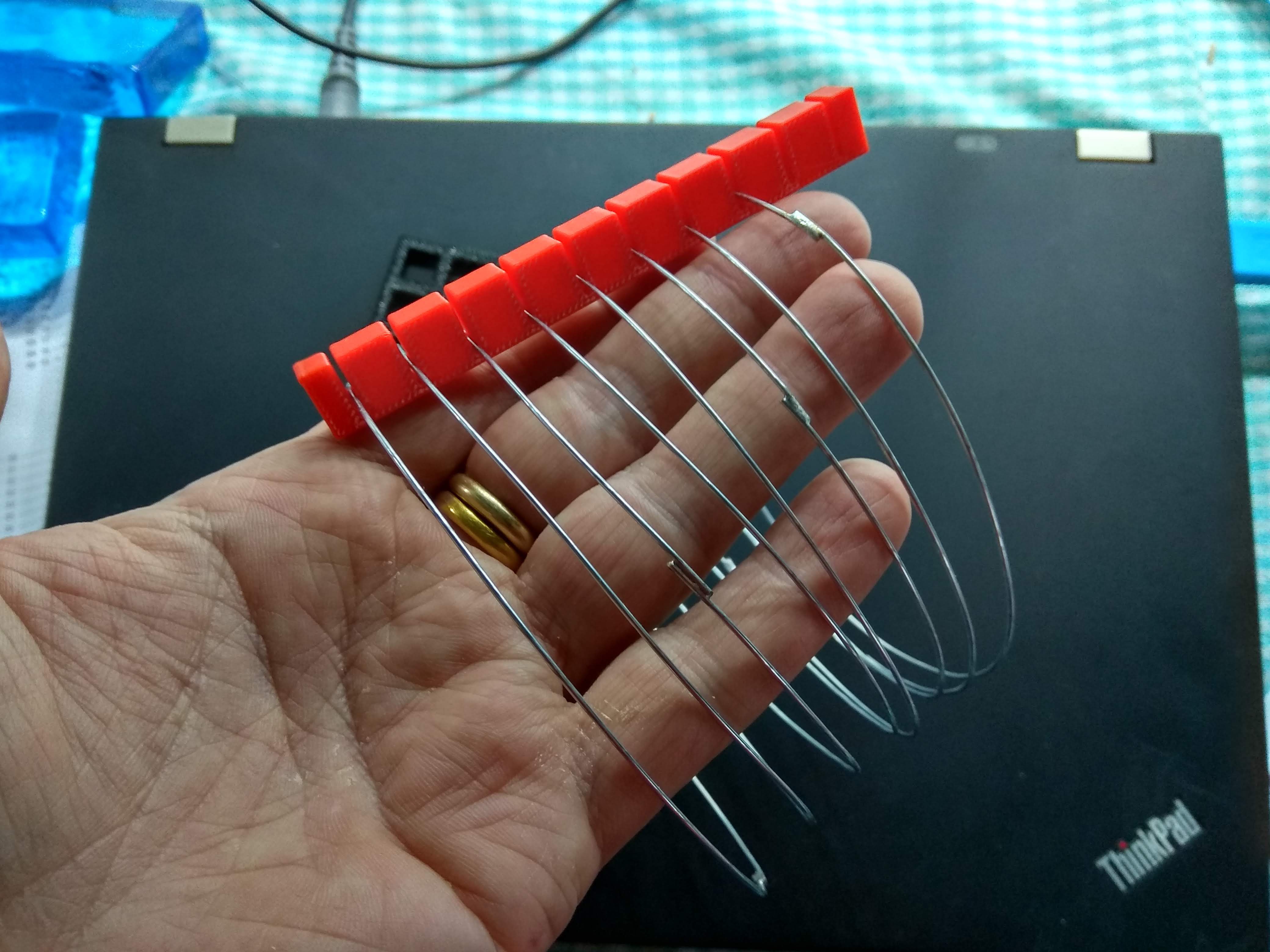
I've been thinking of how to put the rings into a structure. I could 3d-print some plastic structures that looks like giant combs like this (I already had this one laying round from another project):![]()
But it wouldn't be kosher to have ugly plastic parts for structural integrity in this project. Maybe pretty laser cut acrylics would be ok, but I don't have a laser cutter so that's not an option.
If I had a buttload of 1pf ceramic caps in my part cabinets I could just solder three of them between each ring as spacers. Considering that a Z80 machine works just fine on a breadboard that will add 4-5 pf between the lanes a couple of pfs here wouldn't be the end of the world.
But I don't got that many super-low value caps at home either. But I got plenty of small 1M resistors. Using three 1M in parallel gives 300K. So there will be like having a 300K resistor between DB0 and DB1, between DB1 and DB2 and so on. A lot of crosstalk going on. But I'll go out on a limb here and just assume that 300K is so high that the drivers in the ICs will be able to cope with that with their hopefully "superior" current driving capabilities.It probably would have been better to use 10M or even 30M resistors, but.....
-
Straightening wires
12/20/2018 at 21:24 • 0 commentsFirst tings first - I needed to get my hands on some wire that is stiff enough to use for the frame, and preferably not copper since the tin spreads out so much on it when soldering and there's quite a difference in color between the tin and copper. I need all the help I can get to make it as pretty-looking as possible. ;-)
So I found a 100 meter roll of 1mm (AWG 18) steel wire in a local shop and it is easy enough to make nice bends with it using pliers, and it turned out to be almost as easy to solder it as copper wires. Nice!
When unrolling and cutting pieces of the wire that are all bent and crooked so I did a quick search on the net of how to straighten wires in an easy way. Apparently one can just hold onto one end with some pliers and then use a drill to twist the other end slowly. The wire then magically ends up straight as an arrow!
The steel wire and the tools for straightening 
Cut prices that are bent and ugly 
Straight and nice after some twisting with the drill
wirez80
Z80 machine with a hex keypad and 7-segment displays built on a cylindrical wireframe