Chris
Chris-
Tension so thick....
12/31/2018 at 06:16 • 3 commentsFor those of your just tuning in, hello, and welcome. Where we last left off was at a pretty much functional conveyor belt print ejection system for the Printrbot Simple Metal with heated bed upgrade. You can take another look at that below because I think it is pretty cool.
Now you may notice my choice of words here, "pretty much." That is mainly because this project still has one glaring issue, and that is belt tension.
Belt Tension: The Odyssey
There are two major issues when it come to belt tension, print wobble and print warping. Chances are on a 3d printer you are going to encounter prints that will exhibit both of those issues. To being lets start with the warping.
This is a pretty mundane topic at this point because print warping has been occurring since the dawn of time and each hacker has their own favorite way of preventing it. The problem with printing on relatively floppy belt of paper is that paper isn't particularly rigid. This means that as the print is cooling, the corners of the print will begin to curl, ever so slighting taking the paper belt with it. For this most part this could be alleviated with a raft, but why use one if you don't have to?
The issue of print wobble is a bit more exotic, especially in this instance. The jerky motions that the printer normally makes on sharp corners and infil normally don't have all that much of an effect on a rigid piece of plastic. However those rapid movements cause the print to wobble much more than it would if it was anchored to a proper bed. Not to mention I was using flexible filament which meant this wobble would lead to outright failure.
So what is a hacker to do? Make a better design of course! However there were a few design constraints that I wanted to follow. Mainly I didn't want to really increase the part count of the project; I only wanted to make it out of stuff that I had laying around. I also didn't really want to have any more 3D printed parts. As you can see below the structure really just consists of the 4 corners that hold the bed and then the 2 3D printed rollers. I didn't want to add any sort of separate idler or tensioner for the belt to run through
![]()
Below you can see the design that I came up with.
![]()
You'll notice that it is very similar to the picture I posted in the previous log. However this mount has a wider "jaw." This design is taking advantage of the fact that the four holes on the corners of the heated bed are threaded. The basic idea of this design is to use long M3 screws almost like threaded rods. With this method, the basic idea is that you mount the heated bed at the bottom of the "jaw" with the screw, and then attach the belt. as tight as you can make it by hand, and then you just turn the screws, thus raising the entire bed up, and tensioning the belt. It's a bit hard to explain. Check out the animation below.
![]()
![]()
Imagine that the nut is one corner of the bed. Also note that the screw isn't actually being screwed into the plastic. It is just seated in a hole to keep it stable.
With this new design in hand it was just a matter of printing some replacement parts and swapping things out! But of course once you fix one problem another one arises.
Moar Powa!!!!
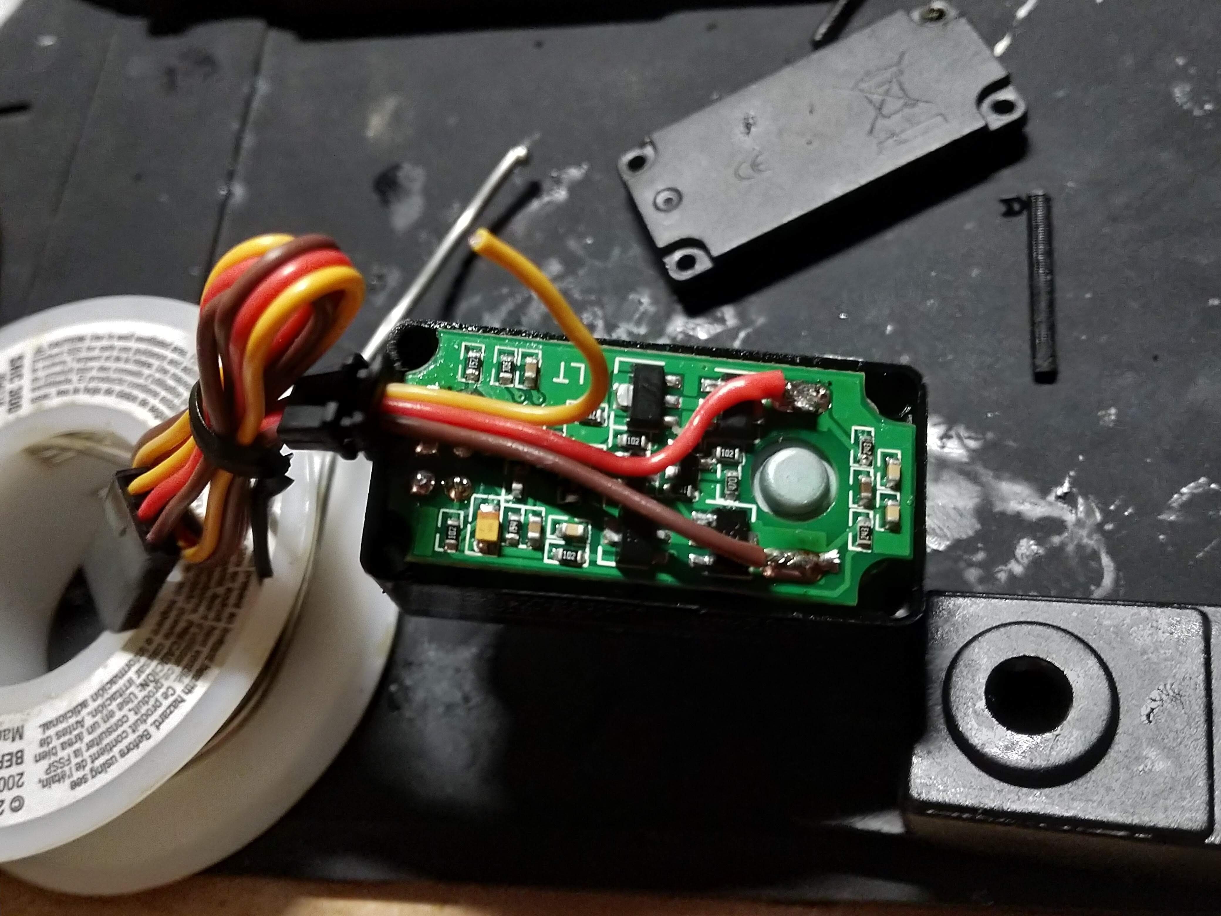
My first print on the newly tensioned belt went very well, and made the entire assembly much more robust. However there was now a new problem. My tiny little motor couldn't handle the increased load! I had originally been using a normal servo motor that I hacked for "continuous rotation." By that I mean that I cracked it open and just soldered the power wires directly to the motor. I really didn't care about position tracking, just the gear box that the servo provided.
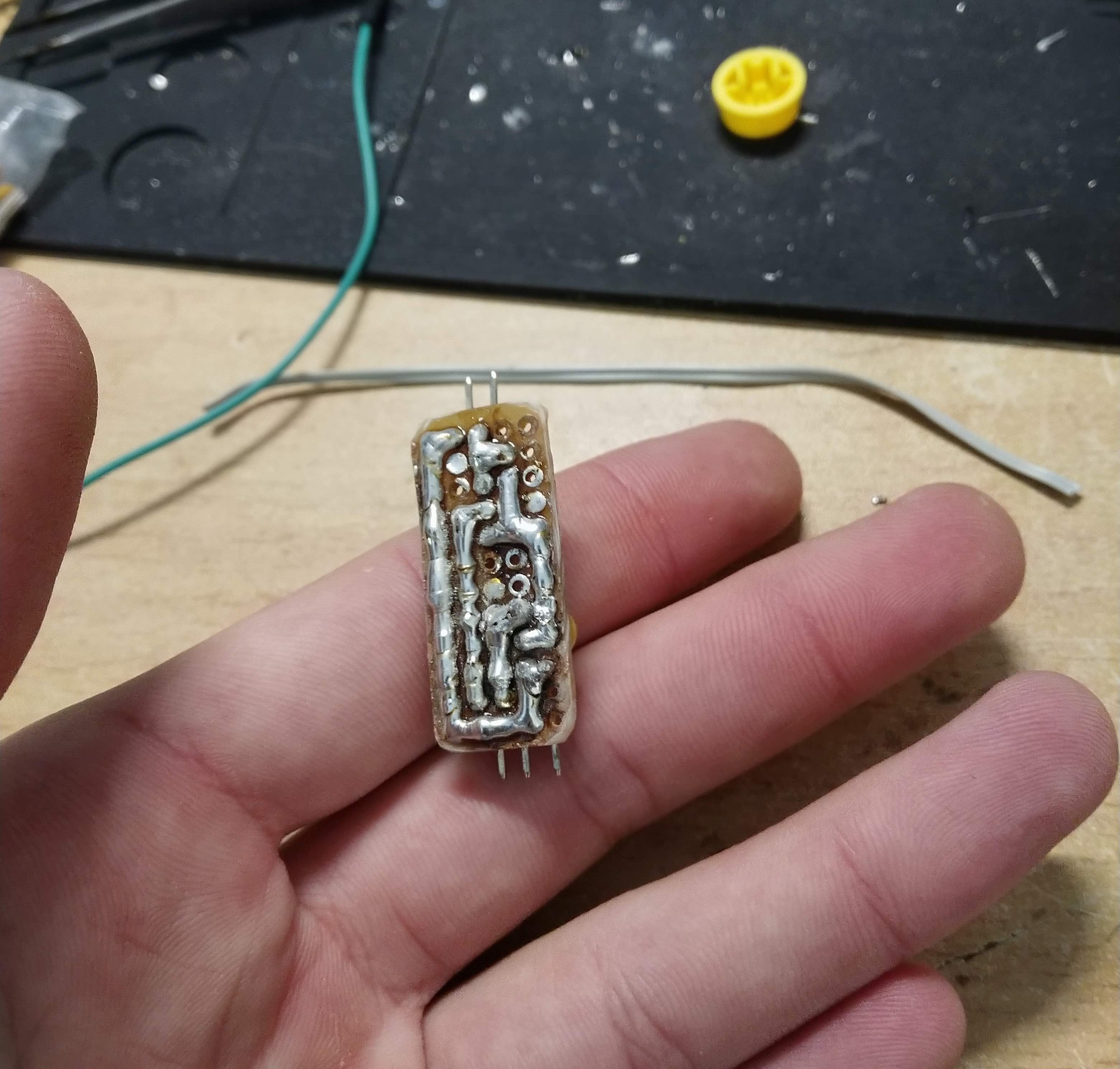
![]()
So here is my Franken-Servo. It's pretty much as hacky as it gets. The datawire isn't even connected lol. This little plastic gear box was adequate when the belt was all loose and floppy but now that we have properly tensioned belt this little guy isn't going to cut it. Not to mention the little homemade driver board couldn't handle the current. I shouldn't really have been surprised considering I was just using a SMD linear regulator soldered to some header. Always room for improvement!
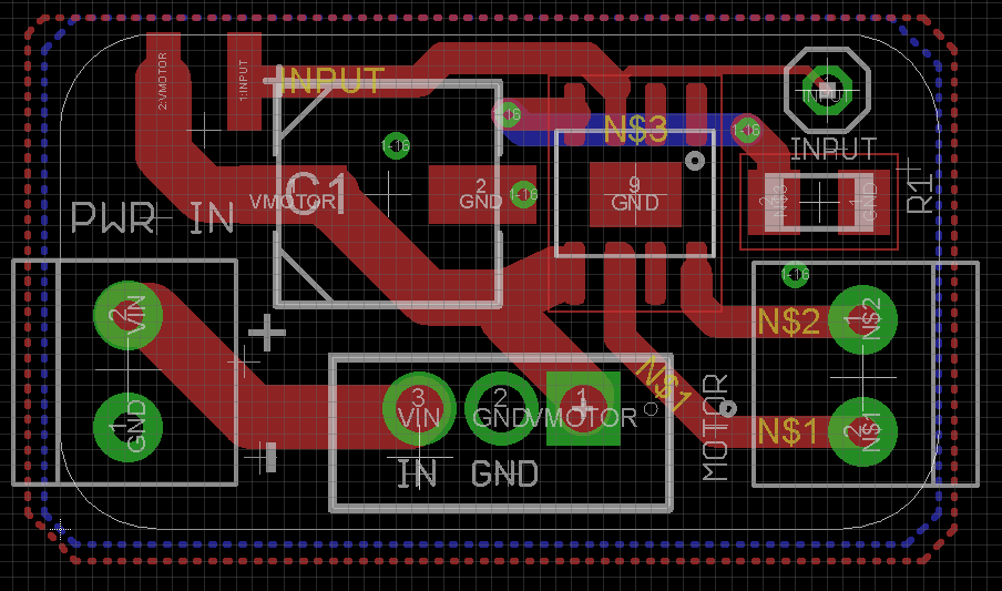
That is why I decided to upgrade to something a little more legit. I made a really simple driver board based around the DRV8871 motor driver and the classic 7805 linear regulator. Based on the constraints of the linear regulator the board should be able to give the motor about 1.5amps sourced directly from the 12v power supply of the Printrbot. That hopefully should be plenty. I also spent a minimal amount of time on the pcb so there are probably going to be some problems but oh well.
I also plan on upgrading to a new motor with more torque than just the servo. It has an all metal gear box and a gear reduction of 1:90 which should be enough to eject even the largest prints on the tightest of belts. The gear is also keyed which is convenient. Hopefully it won't be too much heavier than the servo.
![TT Motor All-Metal Gearbox - 1:90 Gear Ratio]() For now that is all I have. I will eventually post a BOM and maybe even show how I made the belt out of paper and kapton tape if anyone asks. I will post my next update once I have upgraded the motor driver and the motor itself!
For now that is all I have. I will eventually post a BOM and maybe even show how I made the belt out of paper and kapton tape if anyone asks. I will post my next update once I have upgraded the motor driver and the motor itself! -
The First(ish) Try
12/24/2018 at 04:40 • 0 commentsThis project (as many projects do) started as a result of another project in which I needed a way to 3D print LOTS of things for the foreseeable future. Each one of things takes 2-3 hours to print so it wasn't really like I could babysit my printer all day. I wanted a little factory
For a while I was banking on PrintrBot releasing their PrintrBelt, which Brook Drumm had teased on a number of occasions. This printer used the typical angled printer head and belt system of an "infinite build volume" printer. The main difference from other infinite build volume printers on the market is that I suspect it would have been of the high quality and the reasonable cost of PrintrBot Products. Little did I know that it would never see the light of day.
Now of course there are some other people that are working on exactly what I wanted i.e. a printer that could just keep spitting out little bobbles until it ran out of filament with minimal human interaction. Most notable that included this project on Hackaday.io. Swaleh Owais did serve as a bit of inspiration for this project but I thought that there had to be a better way. His custom made infinite build volume printer was pretty cool, but I already had a perfectly good Printrbot Simple Metal. Why not just modify the one that I have?
Why don't we just replace the whole y-axis?
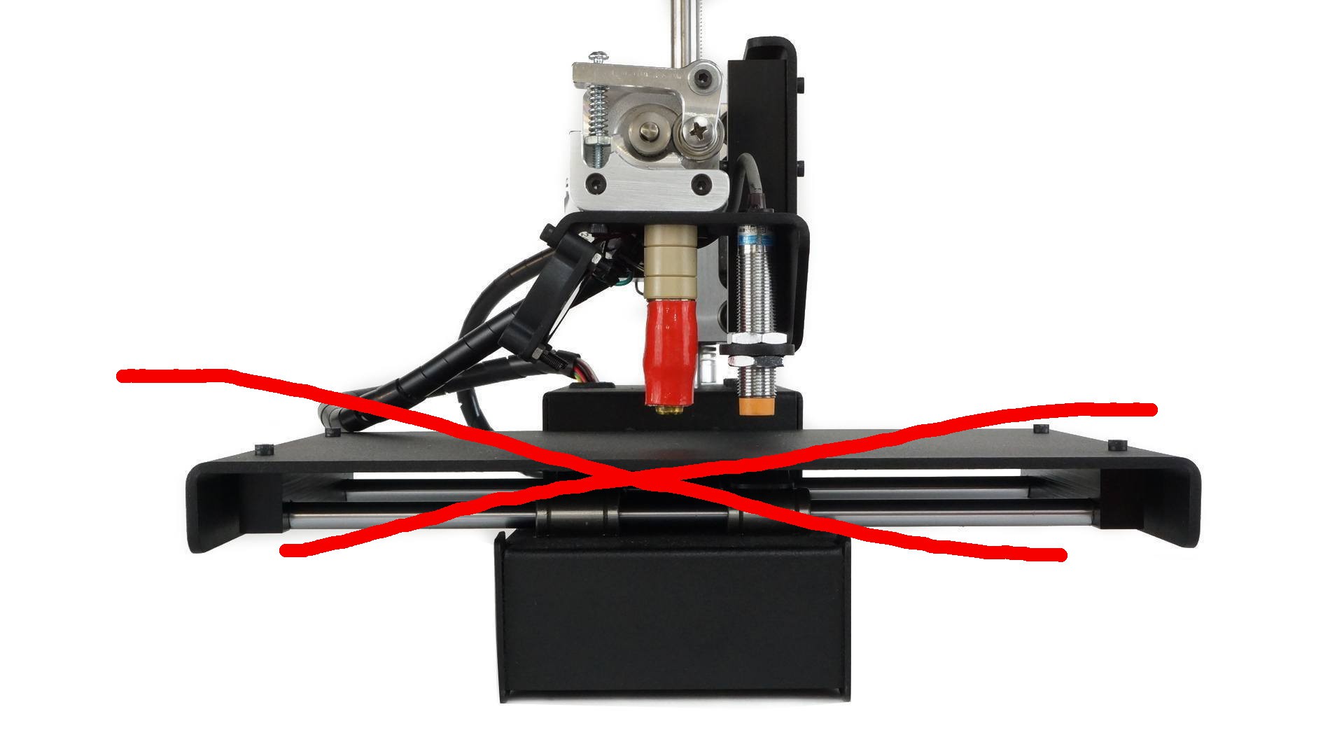
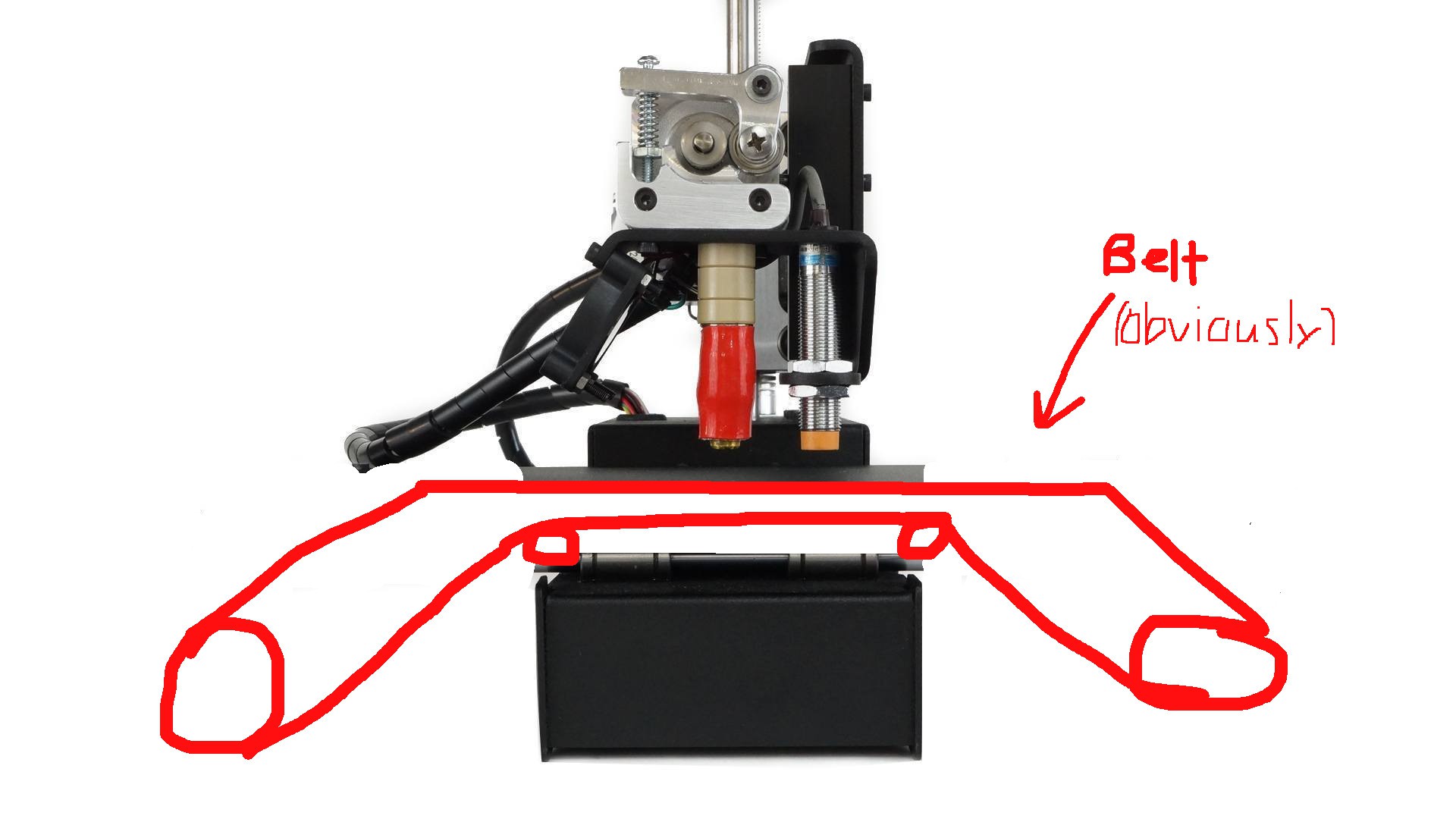
Initially I thought the best approach was going to be to replace the bed of the Printrbot Simple Metal entirely. That would mean that all the y-axis movements would be handled entirely by this hypothetical belt. For those of you who are not familiar with the Printrbot Simple Metal, please see the expertly illustrated rendering below for a general idea of what I was thinking.
![]()
![]()
This seemed like a not so bad idea if you didn't think about it so hard. Of course there were somethings that I had to figure out like how was I going to tension the bed? How was I going to keep this thing as 3D printable as possible without using much after market hardware? What was I going to eat for dinner? Sooo many questions. So the best thing think that I could think of doing was jumping in feet first into some CAD just to get the creative juices flowing and see what I could make. Things were a bit chaotic to say the least.
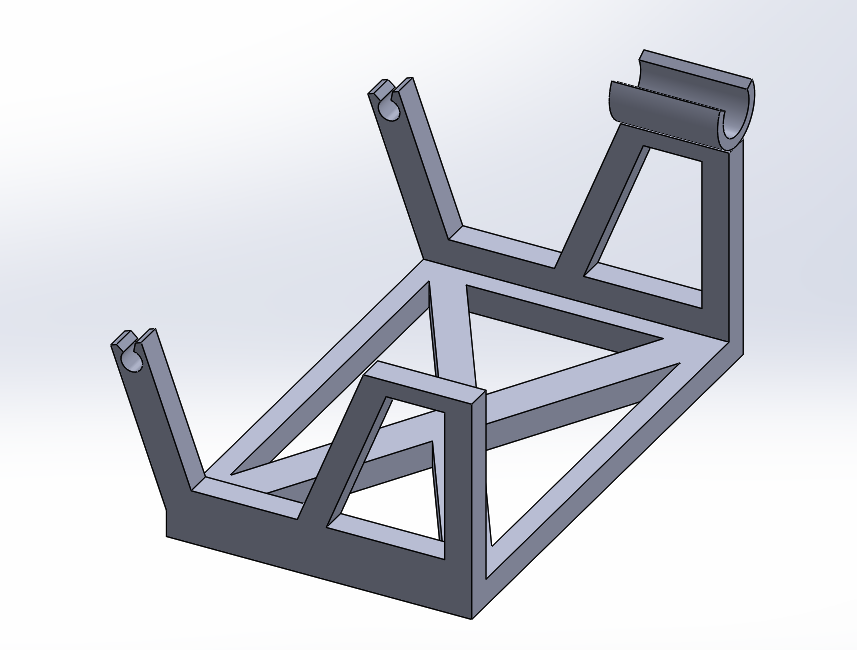
I initially started out thinking that I was going to need some sort of external truss structure type thing on the outside of the print to support the rollers and hopefully give me an idea about how to get an adjust about tension system. Below you can see a picture of one of the earliest attempts to make my dream of a PrintrFactory come true.
Yah. I am honestly not really sure what I was thinking here? I think that the idea was that the scoopy bit in the upper right hand corner would somehow lock y-axis bed assembly and then the two little do-hickeys on the left would be where the roller would slot. Based on the tone of the last few sentences you can probably guess that this didn't get too far. Despite feeling pretty good about this idea initially, I actually did some Googling to see if anyone had attempted this whole belt-replacement nonsense and sure enough someone had done it before......
...and I would love to show you how they went about doing it but for the life of me I cannot find the video. Seriously I think that the internet just gobbled it up. The gist of it was that the madman had his Printrbot Simple (the older laser cut model) clamped down to their desk and they had set up two big rollers that I believe had a belt made of brown (waxed?) paper stretched between them, with one side being driven by the original stepper motor of the y-axis. From what I could tell their solution wasn't viable due to instability and belt splipage. Oh also it needed to be clamped down to a freakin' desk and was like 3 feet across. So either way this poor fellow did the dirty work for me and led me to abandon my initial approach.
If we can't replace the y-axis bed, why not just make it more betterer?
So my next approach seemed to work a little bit better. If figured if we can't replace the y-axis with a belt, then let's just make the belt move along with the y-axis bed that is already there. Once again, although I wish this was original thought, I did have some inspiration from the guys over at 3Dator. They introduced me to the concept they call the "Belt Bed." Watch the quick video below to see what I mean.
Pretty slick right? Sounded a little crunchy but I have to say it was exactly what was after. I want to point out once again that I wasn't really after and infinite build volume printer, more of just a printer that could print infinitely many, fixed volume things. Make sense?
After this video one of my primary question was what the belt was made out of. Obviously it had the familiar golden hue of kapton so we knew that much at least. However, according to the comment section, the belt was "specially made" for the 3Dator people. Uh....okay? I guess we can come back to that (spoiler alert: I just used kapton tape and printer paper!).
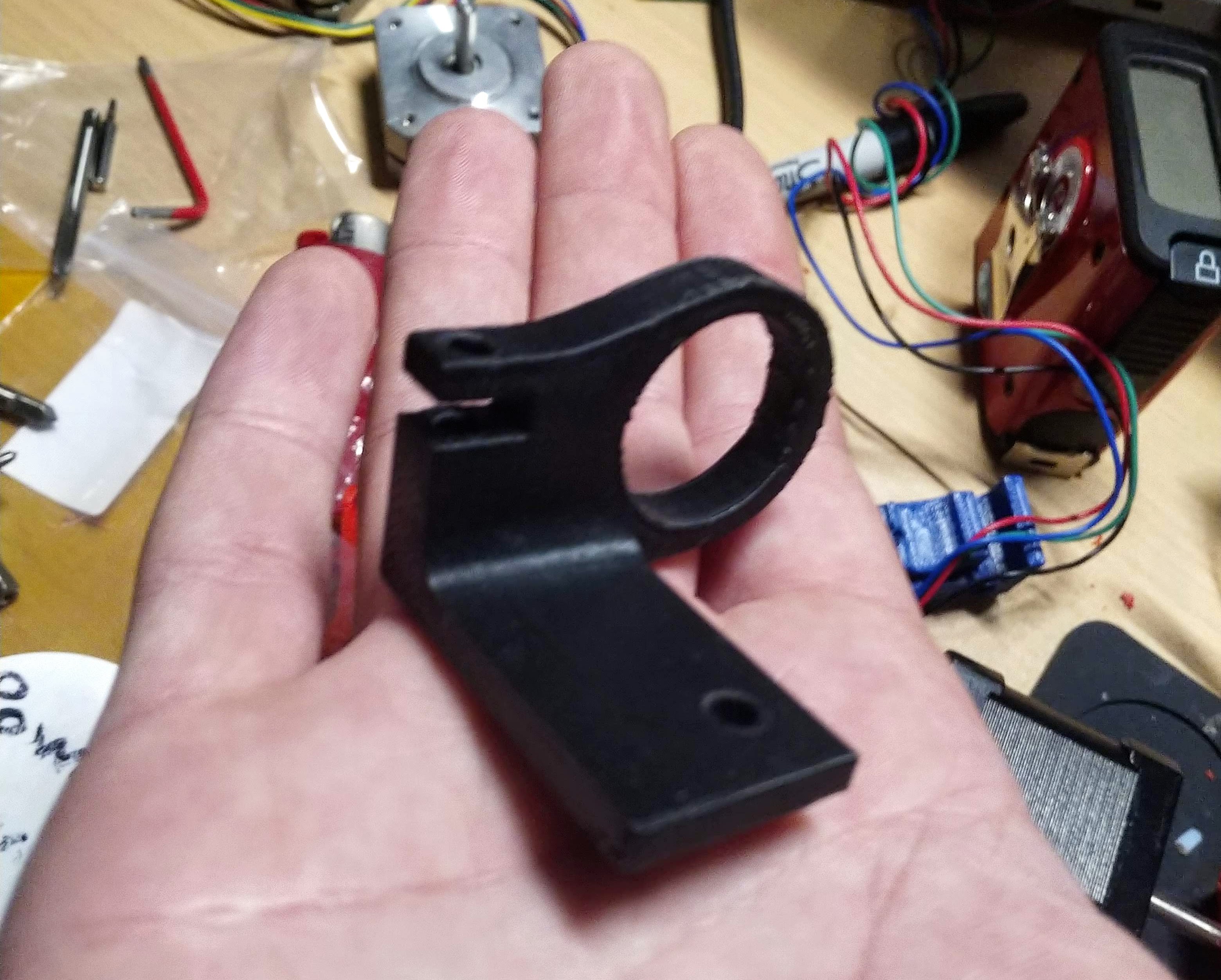
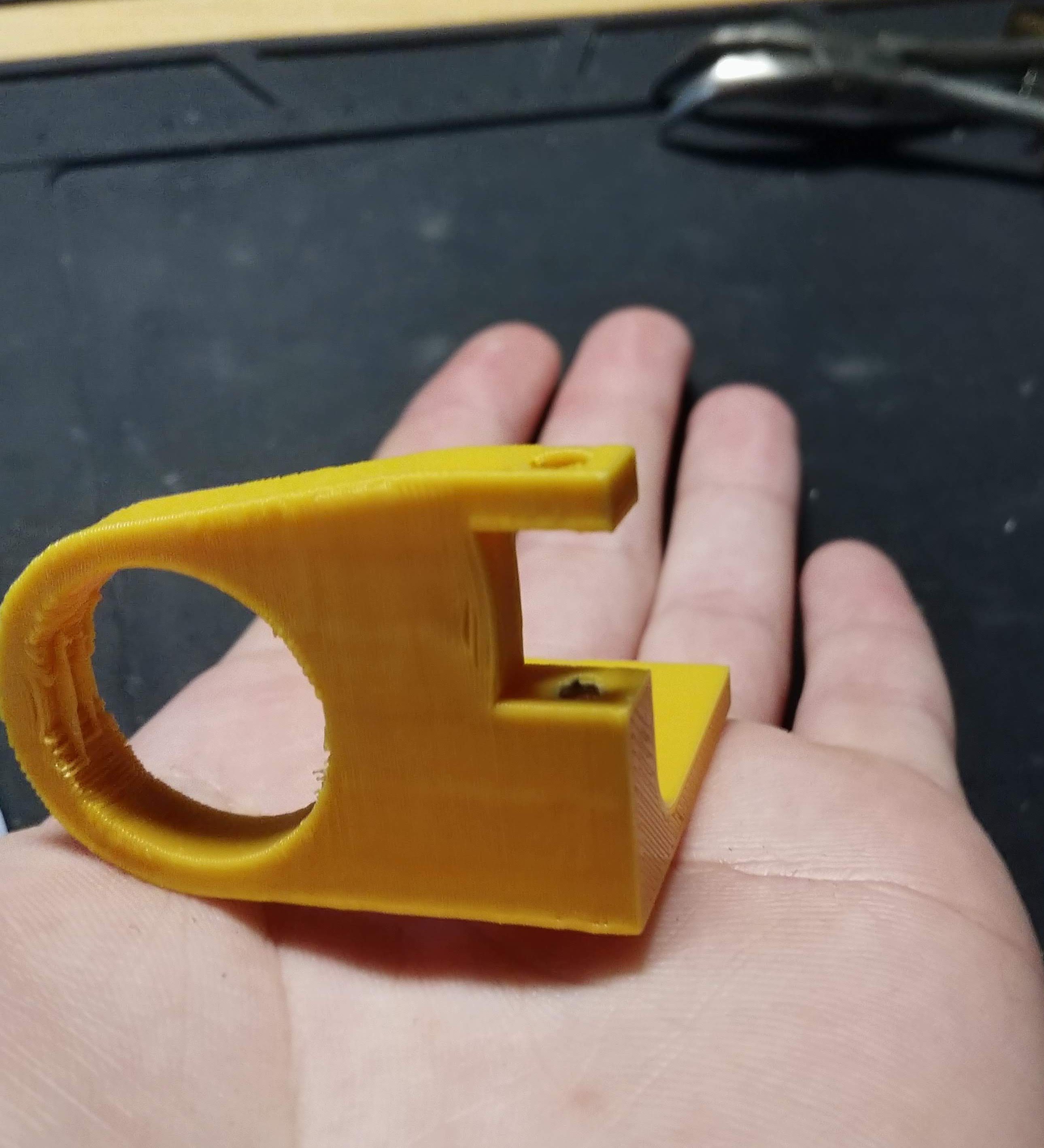
With this new concept of a belt bed in mind I got back to modeling and after a few more sane iterations and virtual measurements, I came up with this cute little guy:
![]()
This post is getting a bit long winded and really is only an introduction into my journey so I will cut to the chase. I printed out 4 of these (with the 4th having a special mount for the motor(not pictured)) and screwed them down to the corners of the y-carriage. The heated bed of the Printrbot would then slot in and be screwed down in that little cut out that you can hopefully see. For the bearings I used just normal 608 inline skate/fidget spinner bearings because my hope was to keep this as limited in aftermarket hardware as possible. I cannibalized some from my little brother's fidget spinners and an old roller skate I found in my garage.
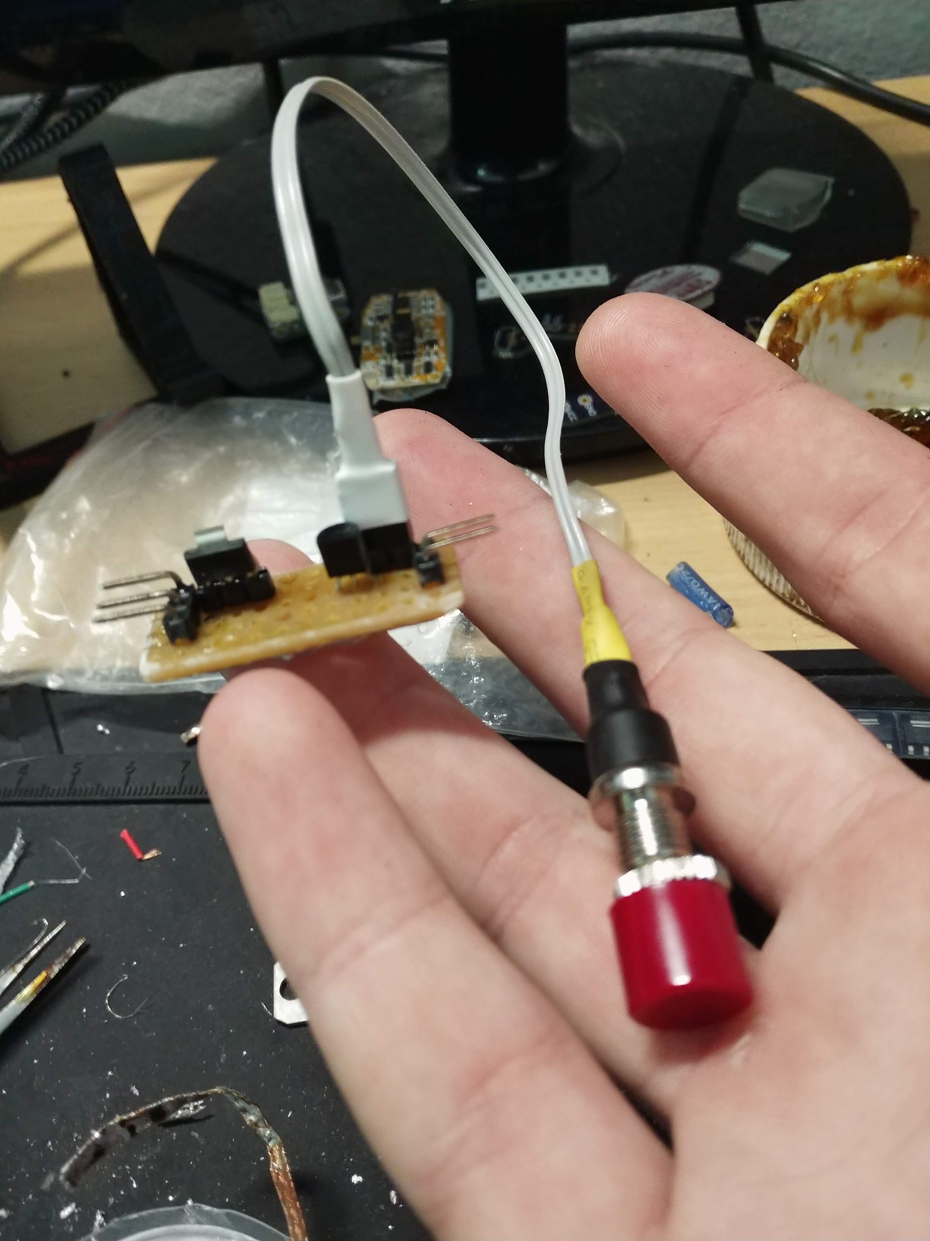
I technically modified a servo for continous rotation, and by that I mean it literally cut out the limiting nubby thing on the gears and soldered the power cables right to the motor terminals. That way I had a nice little gearbox. I then soldered a little motor driver circuit that consisted no more than of a transistor, a SMD linear regulator (that had no idea what it was infor), and some male header to connect everything together. As a nice little touch I also added an "override" button that would spin the motor without any sort of need for software input.
![]()
![]()
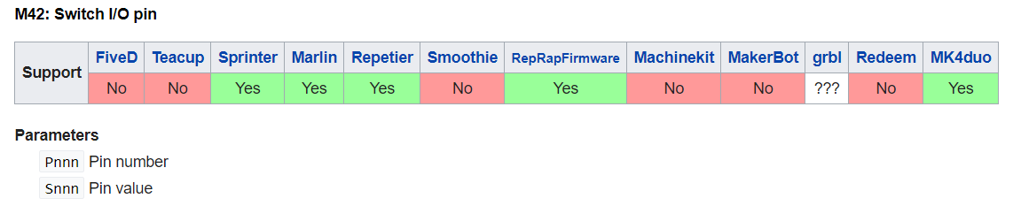
With the mounting hardware and the electronics figured out, all that was left was the software side of things. I just needed a way to toggle one of the spare GPIO pins on the PrintrBoard. I figured that there might already be some sort of gcode command for that and sure enough look at that!!
But of course after fiddling around for a few hours and checking out a whole host of different pin naming schemes, I could not for the life of me figure out why the command was not working. So eventually I just broke down and opened up the Printrbot Marlin code and added my own g-code command to do a digitalWrite to the GPIO pin that I found was the only one to actually toggle when it was supposed to. I thought that was going to be the easy part! However once things had been compiled and flashed and all buttoned up, that is when the magic really happened! Below you can see one of the first automated print ejections of the PrintrFactry Mk1 !!
So there we have it for now. If requested I will go into more detail about things however I think that is a pretty good summation of things so far. However, there was still one major issue with this design bed tensioning. Everything may look fine and dandy in the video but let me tell you that thing was wobbling around so much as it printed. So in the Mk2 design I came up with a pretty clever little design that I think you will enjoy.
and yes I am writing all of this in the past tense. I have made some pretty good progress so far and I figured that I would try to play my part on the internet and try to document what I have done this far. Let me know what you think of all of this!
PrintrFactry
Printrbot may have shutdown, but I want my mini factory gosh darnit

 For now that is all I have. I will eventually post a BOM and maybe even show how I made the belt out of paper and kapton tape if anyone asks. I will post my next update once I have upgraded the motor driver and the motor itself!