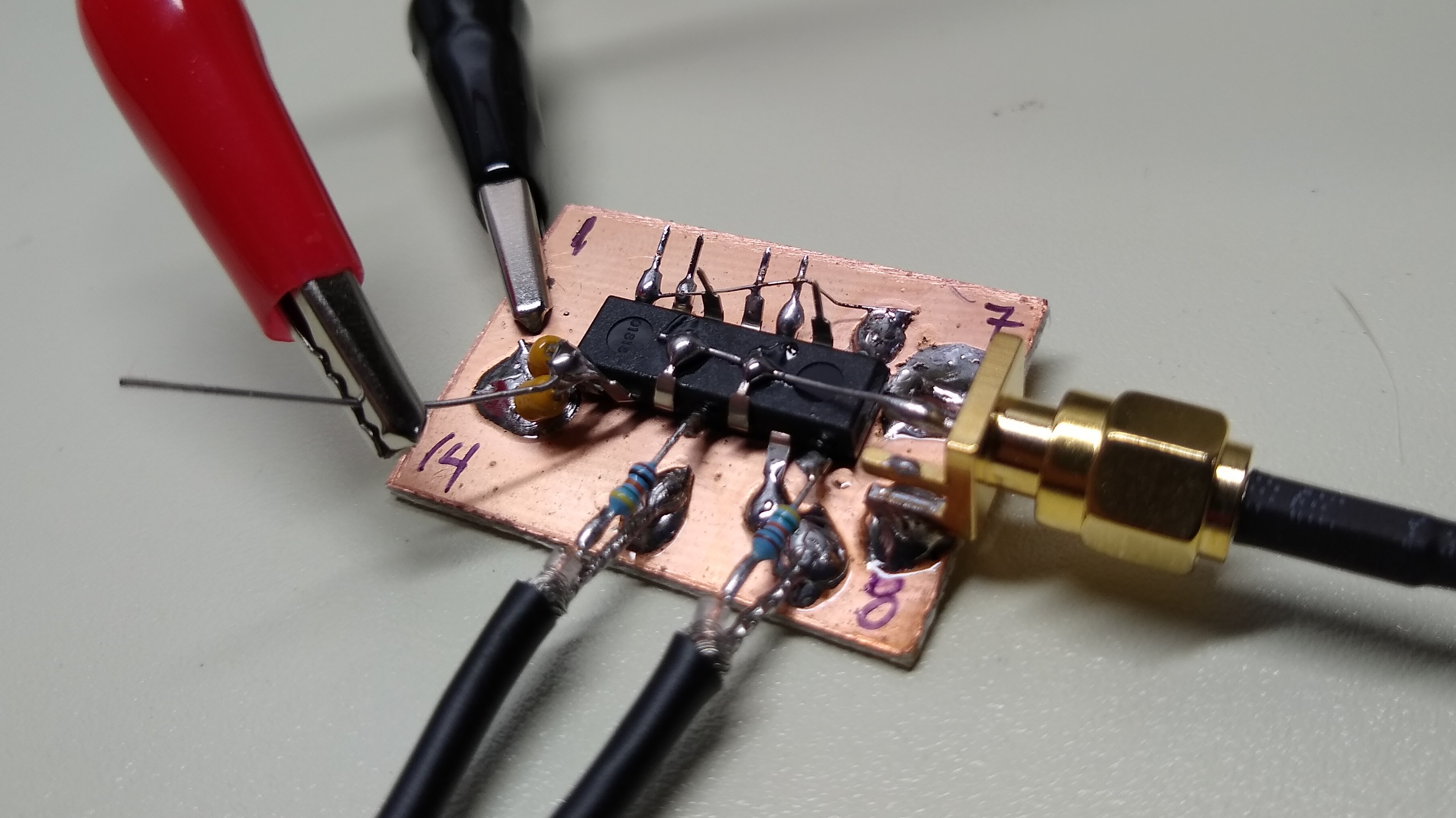
In the last log, I speculated about using a pair of XOR gates to get a complementary (differential) pair of outputs from CMOS logic. This brought up a lot of questions, and the best cure for that is some quality bench time. I threw a 74AC86 XOR package on some copper clad and tested it out.
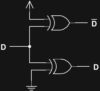
It's the same idea from the last log: use two XOR gates, one as an inverter, one as a pass-though, and hope that the skew between the two outputs is low.
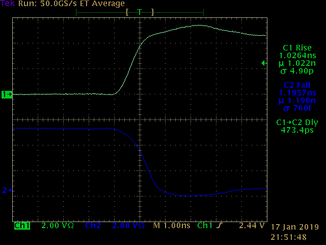
The output shows around 570 ps of skew. Compared to the 1 ns rise/fall times of the signals, this isn't really very good.

I wasn't sure how much this skew was due to differences between the individual gates, or to the different delay when used as an inverter (as predicted by @salec ). To test this out, I swapped the gates around, and measured around 470 ps of skew. A little algebra convinced me that this means there's 50 ps difference between the two gates themselves, and around 520 ps difference due to using one of them as an inverter.
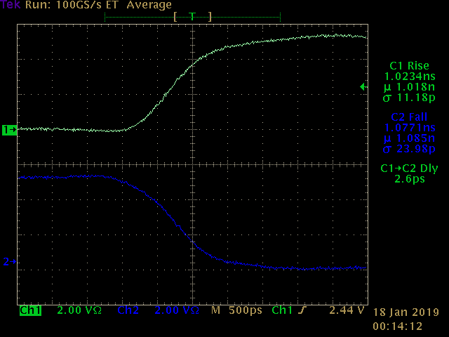
520 ps skew on a signal with 1000 ps edges ain't great. But, in absolute terms, this is small enough to "tune away" with a potentiometer or other adjustable delay, as suggested by @Yann Guidon / YGDES.
EDIT
Sleep is over-rated. I tuned this thing instead. I added two 10 Ohm resistors and a 15-70 pF cap. With some careful adjustment, I reduced the skew to 2.6 ps! It's not very stable at that value, but it seems to stay in the single digits to teens. A skew this low is kind of meaningless when you consider that the difference in rise and fall times is around 70 ps. I think the conclusion is that you can, indeed, just tune this thing until it works.
For completeness, here's the new circuit.

The trimmer is difficult to adjust - the only tools I have that will fit in there are metal screwdrivers, and they add their own capacitance to the circuit. You have to over-compensate so that when the screwdriver is removed, the circuit ends up tuned. It takes a few tries. Maybe I need to print some alignment tools?
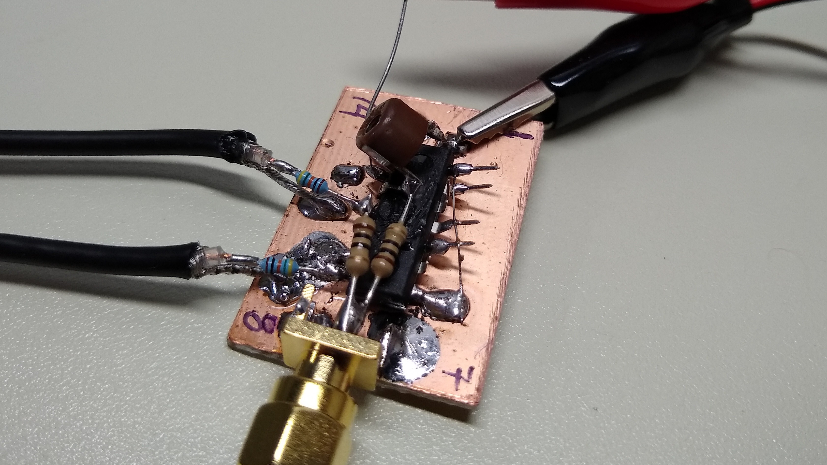
The probes deserve a mention, too - these are simply 453 Ohm resistors soldered on to the end of a length of RG174 cable. Combined with the scope's 50 Ohm terminators, they make 10:1 probes with a decent bandwidth, much better than commercial probes I can afford. To make these two, I just cut a cheap BNC cable in half - as close to exactly half as possible to maintain equal delays.
EDIT 2019-01-19
I read in "High Speed Digital Design: A Handbook of Black Magic" about using varactors to tune logic delays. I had a selection of 10 different types of varactors in the diode bin, and chose an NTE618 for a test - this is a device originally designed for AM tuners. It has a wide capacitance range 20-460 pF, although you need up to 15 V reverse bias to push it to low values. I put it in series with an 82 pF fixed cap, and biased it through a 10 K resistor and a voltage divider.
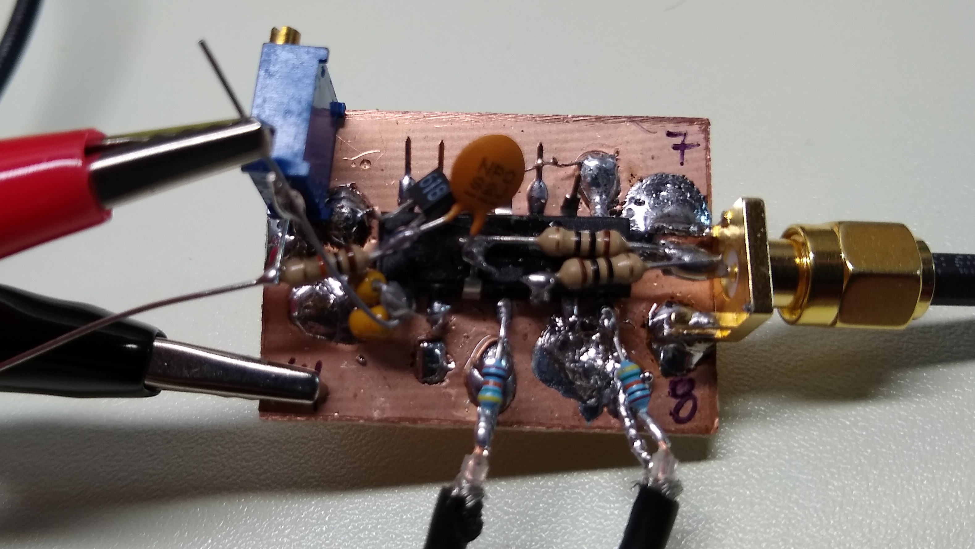
It's the same idea as the trimmer cap version, but now electronically tunable.
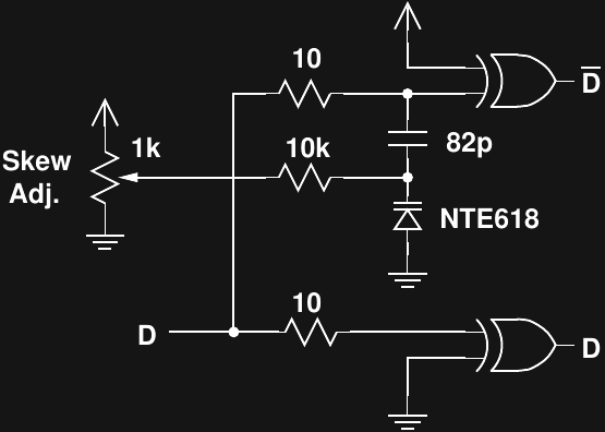
With the components used, the tuning range is around 310 ps. This is enough to fine-tune the delay if you can get it in the ballpark first. The varactor drifts with temperature, though, so some kind of automatic calibration that could periodically adjust it would be nice.
This is probably overkill for the planned use, but an interesting experiment nonetheless.
 Ted Yapo
Discussions
Become a Hackaday.io Member
Create an account to leave a comment. Already have an account? Log In.
at these speeds, everything counts... it becomes black magic :-D
Are you sure? yes | no
yes, I am (slowly) finding that out :-(
Are you sure? yes | no